AGING PHENOMENA IN FERROUS MARTENSITES
by
KEITH ALLEN TAYLOR
S.B., Massachusetts Institute of Technology (1980)
Submitted in partial fulfillment of the requirements for the degree of
DOCTOR OF SCIENCE
at the
MASSACHUSETTS INSTITUTE OF TECHNOLOGY June 1985
QMassachusetts Institute of Technology
Signature of Author
Department of MateriAXr Science and -- ,A
Engineering May 3, 1985 Certified
by-John B. Vander Sande
19 Thesis Supervisor Certified by /
7)
Gregory B. Olson Thesis Supervisor Certified by Morris Cohen Thesis Supervisor Accepted byChairman sD partmental Committee
Bernhardt J. Wuensch on Graduate Students
Archives
- A,- F " F I - -AGING PHENOMENA IN FERROUS MARTENSITES
by
KEITH ALLEN TAYLOR
Submitted to the Department of Materials Science and Engineering on May 3, 1985 in partial fulfillment of the requirements
for the Degree of Doctor of Science in Metallurgy
ABSTRACT
Transmission electron microscopy (TEM) and electrical resistivity measurements have been used to follow the aging and first stage of tempering of martensitic steels. TEM was employed to study structural changes directly, while the resistivity measurements provided important kinetic data. Two Fe-Ni-C alloys (Fe-25Ni-0.4C and Fe-15Ni-iC) with subambient Ms temperatures were selected for this study in order to
eliminate the complications of autotempering which are normally encountered in binary Fe-C alloys.
The martensites of both alloys display the common plate-like
morphology. The substructure consists of {112} transformation twins, <111> lattice screw dislocations, as well as planar defects having a {011} habit. Carbon atoms tend to occupy only one of the three available octahedral interstitial sublattices in virgin martensite; however, the carbon atoms in
{011} defects are related to those in their surroundings by a twinning operation on {011}. Moderate volume fractions of such twins are sufficient to account for anomalous axial ratios previously measured in these
martensites.
Aging at room temperature results in the rapid development of a structural modulation along the four equivalent <203> directions of the tetragonal martensitic structure. The result is a fine-scale "tweed" morphology which is readily detected by TEM throughout the entire
martensitic phase. The initial wavelength decreases with the alloy carbon content; it is about 2.5 and 1.5 nm for Fe-25Ni-0.4C and Fe-15Ni-1C,
respectively. The activation energy (Q) is initially about 84 kJ/mole (20 kcal/mole), but increases by about 10 kJ/mole during aging. However, in the early stages of aging Q is consistently 8 - 25 kJ/mole higher in Fe-15Ni-iC as compared to Fe-25Ni-0.4C. The magnitude of Q indicates that carbon diffusion is the single rate-controlling process during aging. The increase in Q with carbon content is qualitatively consistent with
predictions of a concentration dependence of the diffusivity of carbon in tetragonal martensite. The martensitic substructure does not appear to exert any substantial influence on the overall aging process.
Results from a concurrent atom-probe study at Oxford University show that the tweed structure represents a periodic modulation in carbon
concentration and that the composition amplitude increases with aging time; prolonged aging of Fe-15Ni-lC at room temperature leads to alternating carbon-rich and carbon-poor bands containing about 11 and 0.2 at pct
carbon, respectively. The increase in composition amplitude and the aligned nature of the aging product indicate that a coherent spinodal decomposition is occurring. Given the ordered nature of virgin martensite as well as some previous evidence for secondary ordering during aging, it appears appropriate to call the reaction a conditional spinodal
decomposition. A simple phenomenological thermodynamic model is presented which predicts a miscibility gap (consistent with the atom probe results) in the Fe-C system when a carbon ordering energy is included.
Spinodal decomposition is followed by transition carbide precipitation both at and above room temperature. The carbides do not display hexagonal symmetry. They may be a partially ordered version of the e-carbide
structure, e.g. the n-carbide structure proposed in other recent TEM
studies. The carbides adopt a plate-like shape with a habit near {102} and exhibit basal plane stacking faults which are spaced at 1 - 1.5 nm
intervals. The morphologic and crystallographic features of these carbides are explained in terms of an invariant-plane strain transformation. There is strong evidence that carbides nucleate heterogeneously on the carbon-rich bands which form during aging. Nucleation is aided by the favorable shape strain which relates a tetragonally-distorted high carbon band to its low-carbon surroundings. The similarity of the carbide and spinodal habits enables the carbide to align with the interface between high- and low-carbon bands and thereby take advantage of the available interfacial free energy. No nucleation was directly observed on lattice dislocations; however {112} twin boundaries can influence the precipitation behavior.
The apparent activation energy increases to 125 - 145 kJ/mole (30 - 35 kcal/mole) during tempering. The continuous increase during aging and on into tempering indicates that the kinetics of carbide precipitation become influenced by a process other than carbon diffusion. It is suggested that the propogation of the martensite/carbide interface, as well as carbon diffusion, are the processes which influence the carbide growth rate; the conservative nature of the invariant-plane strain which converts carbon-enriched martensite to the transition carbide does not require any
intrinsic diffusional transport of metal atoms for sustained growth. The two alloys of this study exhibit identical aging and tempering behavior, apart from slight differences in kinetics. The similarity of the current {203} tweed and the {102} tweed in Fe-C, Fe-Cr-C, and Fe-Mn-C
alloys indicates that spinodal decomposition is an aging reaction common to a wide variety of iron-base carbon martensites. Moreover, the severe
coherency strains associated with decomposition may be responsible for the inherent brittleness of nominally untempered martensites.
Thesis Supervisors: Dr. John B. Vander Sande
Professor of Materials Science Dr. Gregory B. Olson
Principal Research Associate Dr. Morris Cohen
TABLE OF CONTENTS Chapter Page Number Number TITLE PAGE... 1 ABSTRACT...2 TABLE OF CONTENTS...4 LIST OF FIGURES...8 LIST OF TABLES...17 ACKNOWLEDGEMENTS...18 1 INTRODUCTION...20 2 LITERATURE REVIEW...22 2.1 Martensite Formation...22
2.2 The Structure of Austenite...24
2.3 The Structure of Virgin Martensite...28
2.4 Martensitic Morphology and Substructure...33
2.5 The Aging and Tempering of Martensite...39
2.5.1 The Stages of Tempering...40
2.5.2 Studies of Aging...45
2.6 Substructural Effects on Aging and Tempering...48
2.7 Summary...50
3 PURPOSE AND PLAN OF STUDY...52
4 EXPERIMENTAL PROCEDURES...53
4.1 Materials Selection and Processing...53
4.2 Optical Metallography...55
4.3 Electron Metallography...56
4.4 Electrical Resistivity Measurements...57
Page Number RESULTS AND DISCUSSION: MARTENSITIC MORPHOLOGY
AND SUBSTRUCTURE...59 5.1 Martensite Formation... 5.2 Twinning on {112}... 5.3 <111> Screw Dislocations... 5.4 Twinning on {011}... 5.5 Summary... 6 ELECTRICAL RESISTIVITY BEHAVIOR AND THE
MA V N
KNETICS__, OF AINGiM Ia TZE P RILN...
6.1 General Features of the Resistivity Behavior. 6.2 The Kinetic Analysis... 6.2.1 Basic Assumptions... 6.2.2 Methods... 6.2.3 Results and Discussion... 7 RESULTS AND DISCUSSION: SPINODAL DECOMPOSITION
DURING AGING... 7.1 Formation of a Modulated Structure... 7.1.1 Diffuse Electron Scattering and "Tweed" 7.1.2 Image Contrast Theory... 7.1.3 Effect of Martensitic Substructure
on Aging Behavior... 7.1.4 Coarsening of the Tweed... 7.2 Discussion... 7.2.1 Concomitant Spinodal Decomposition 7.2.2 Rationalizing the Tweed Habit...
and
Contrast
Ordering. ....
7.3 Thermodynamics of Decomposition...144 7.3.1 Descriptions of the Body-Centered Fe-C Solution. 7.3.2 An Alternative Thermodynamic Description... Chapter Number 5 .. 59 .. 65 .. 68 .. 72 .. 85 .. 87 .. 87 .. 94 .. 94 .101 .103 .107 .108 .108 .121 .127 .128 .131 .131 .142 .144 .151
Chapter Page
Number Number
7.3.3 Predictions of the Current Model...157
7.4 Summary...164
8 RESULTS AND DISCUSSION: TRANSITION CARBIDE PRECIPITATION...166
8.1 Carbide Morphology...166
8.2 Carbide Crystallography and Substructure...172
8.3 Effect of Martensitic Substructure on Precipitation Behavior...181
8.4 Application of the Bowles-MacKenzie Crystallographic Theory to e'-Carbide...188
8.4.1 Lattice Deformation...191
8.4.2 Internal Accommodation Deformation...195
8.4.3 Predictions of the Analysis...199
8.5 Discussion...204
8.5.1 Carbide Morphology and Structure...204
8.5.2 Orientation Variants...207
8.5.3 Heterogeneous Nucleation...208
8.5.4 Growth Kinetics...209
8.6 Summary...213
9 SUMMARIZING DISCUSSION...215
9.1 Martensitic Crystallography and Substructure...215
9.2 Aging Behavior...216
9.3 Transition Carbide Precipitation...219
10 CONCLUSIONS...224
Appendix Page
Number Number
A CALCULATING THE ELECTRICAL RESISTIVITY OF MARTENSITE...229
B TRANSFORMATION OF AUSTENITE TO MARTENSITE DURING LOW-TEMPERATURE AGING...232
B.1 Introduction...232
B.2 Electrical Resistivity Measurements...233
B.3 Saturation Magnetization Measurements...233
B.4 Results and Discussion...236
C THE ROLE OF SUBSTRUCTURE IN AUTOTEMPERING...244
D OXIDATION OF TEM THIN FOILS...251
D.1 Oxide Crystallography...251
D.2 Oxide Occurrence and Morphology...258
D.3 Discussion...264
E RESULTS OF THE BOWLES-MACKENZIE ANALYSIS...266
REFERENCES...269
LIST OF FIGURES
Figure Page
Number Number
2-1 The iron-carbon phase diagram, (A). An enlargement of 23 the region most important for steel treating is shown in
(B). The metastable system iron-cementite (Fe 3C) is denoted by dashed lines (from Chipman [3]).
2-2 Schematic representation of the FCC structure showing 27 octahedral and tetrahedral interstitial sites (from
Leslie [15]).
2-3 The Bain distortion for the FCC -+ BCC transformation. 29
The BCT cell is outlined in the FCC structure in (A), and shown alone in (B). The Bain distortion converts (B) to (C) (from Reed-Hill [17]).
2-4 Schematic representation of the BCC structure showing 31 octahedral and tetrahedral interstitial sites (from
Leslie [15]).
2-5 The morphology and Ms temperature of iron-nickel-carbon 35 martensites as a function of composition (after Winchell
[34]).
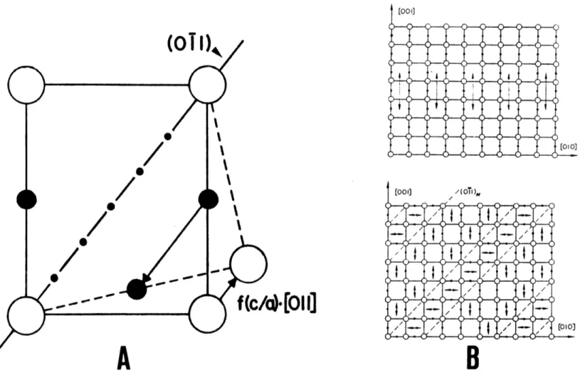
2-6 The <011>{011} twinning system in BCT lattices. Location 38 of lattice and Oz sites in the (100) plane, (A). The
directions of the tetragonal axes are indicated both before and after [011](Oi1) twinning. Such twinning transforms Oz to 0 sites, (B) (from Sachdev [42] and Kurdjumov and Khachaturyan [40]).
5-1 Optical micrographs of austenitic Fe-25Ni-0.4C (A) and 62 Fe-15Ni-1C (B). Both samples were austenitized one hour
at 9500C, followed by water quenching.
5-2 "Butterfly" martensite near the edge of a mechanically- 64 polished sample of austenitic Fe-15Ni-iC. (B) is a
higher magnification view of part of the region shown in (A). This sample was austenitized one hour at 10600C.
5-3 Optical micrographs of Fe-25Ni-0.4C (A) and Fe-15Ni-iC 66 (B) after quenching to -196 0C.
5-4 Bright-field electron micrographs of the midrib region of 67 martensitic Fe-25Ni-0.4C. The thin {112} transformation
twins are viewed in an edge-on orientation in (A). A lower magnification view of a different martensitic plate is shown in (B), where the twins, inclined to the
electron beam, rapidly decrease in number and become more fragmented in moving away from the midrib (MR) (see text for discussion).
Figure Page
Number Number
5-5 Bright-field (g = 020) electron micrographs of 69 dislocation structures in martensitic Fe-25Ni-0.4C and
Fe-15Ni-lC (B). The projections of the four <111>
directions are shown in (A). In (B), the feature marked "T" is a {112} twin (see text).
5-6 Bright-field electron micrograph of dislocation structure 73 in martensitic Fe-25Ni-0.4C. The habit plane is nearly
parallel to the beam direction ([115]) in this image. An adjacent martensitic plate appears in the lower portion of the micrograph.
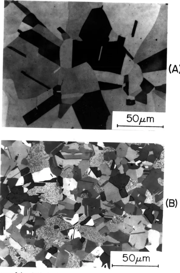
5-7 Bright-field- electron micrographs of {011} planar 75 features in martensitic Fe-25Ni-0.4C. g = 110 and g =
020 in (A) and (B), respectively.
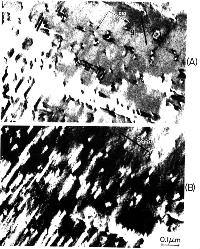
5-8 Bright-field electron micrographs of {011} planar 76 features in martensitic Fe-15Ni-1C. g = 110 and g = 020
in (A) and (B), respectively. The midrib is denoted by "MR." This foil is some 2-3 times thicker as compared with that of Figure 5-7 and therefore the planar features exhibit more fringes.
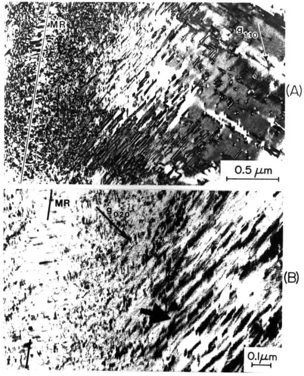
5-9 Bright-field electron micrographs of {011} planar 78 features in martensitic Fe-25Ni-0.4C. g = 110 and g =
020 in (A) and (B), respectively. The midrib is denoted by "MR."
6-1 Schematic electrical resistivity vs. log(time) behavior 88 (after Sherman et al. [70]).
6-2 Relative resistivity (at -196 0C) of two-phase (austenite 90
+ martensite) Fe-Ni-C alloys after
aging/tempering one hour at the indicated temperature.
6-3(A) Resistivity at -196 0C vs. log(time) for Fe-25Ni-0.4C (85% 92 martensite), aged/tempered at the indicated temperatures.
6-3(B) Resistivity at -1960C vs. log(time) for Fe-15Ni-1C (67% 93 martensite), aged/tempered at the indicated temperatures.
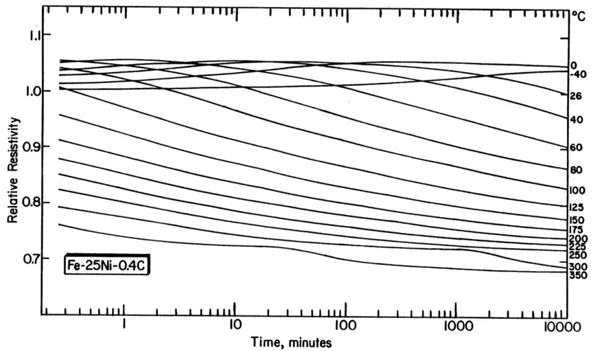
6-4(A) Resistivity at -196 0C (corrected for retained austenite) 95 vs. log(time) for martensitic Fe-25Ni-0.4C, aged/tempered
at the indicated temperatures. The resistivity of virgin martensite is 25.3pSI-cm.
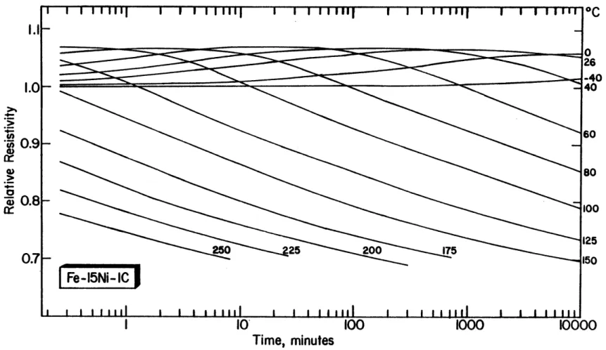
6-4(B) Resistivity at -196 0C (corrected for retained austenite) 96 vs. log(time) for martensitic Fe-15Ni-1C, aged/tempered
at the indicated temperatures. The resistivity of virgin martensite is 36.3pQ-cm.
Figure Page
Number Number
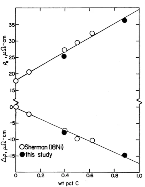
6-5 Resistivity of virgin martensite (p0) and total 100 resistivity change attending complete tempering (Ap = p0
- pe) as a function of carbon concentration for various Fe-Ni-C alloys.
6-6 Activation energy (Q) vs. fraction transformed (f) for 104 Fe-25Ni-0.4C and Fe-15Ni-1C. Values of Q at various
points on the regime II resistivity peak are also shown.
7-1 Three electron diffraction patterns from different 109 martensitic Fe-25Ni-0.4C specimens. The beam direction
and aging times are [100]/2 hrs, [331]/40 min, and [1ii] /2.5 hrs in (A), (B), and (C), respectively.
7-2 Three electron diffraction patterns from different 110 martensitic Fe-15Ni-1C specimens. The beam direction and
aging times are [100]/26 min, [331]/1.75 hrs, and [11] /9.5 hrs in (A), (B), and (C), respectively.
7-3 Two diffraction patterns with the incident beam deviating 112 slightly from the [001] direction. (A) is from
martensitic Fe-25Ni-0.4C, aged 4 hrs at room temperature and (B) is from martensitic Fe-15Ni-iC, aged 6 days at room temperature.
7-4 Cubic [001] stereogram showing the projected directions 114 of the DS present in the four diffraction patterns of
Figures 7-2 and 7-3(B).
7-5 Transmission electron micrographs (bright-field/dark- 115 field pair) of martensitic Fe-l5Ni-1C, aged 5.5 hrs at
room temperature (g = 020). Arrows indicate strain contrast at dislocations.
7-6 Martensitic Fe-15Ni-1C, aged 3 hrs at room temperature. 117 (A) Dark-field transmission electron micrograph taken
with the 020 reflection and its associated diffuse intensity. (B) Diffraction pattern. (C) Optical diffraction pattern from circled region in (A).
7-7 Bright-field (g = 011) transmission electron micrograph 119 of martensitic Fe-25Ni-0.4C, aged 1.75 hrs at room
temperature. The specimen orientation is near [100].
7-8 [100] diffraction patterns from four different alloys. 120
7-9 Variation of the initial tweed wavelength with carbon 122 content. Solid circles are the data of Kusunoki and
Nagakura [88] and open circles are data from the present investigation, obtained after aging several hours at room temperature.
Figure Page
Number Number
7-10 Martensitic Fe-25Ni-0.4C, aged 4 hrs at room temperature. 123 (A) Dark-field transmission electron micrograph taken
with the 110 reflection and its associated diffuse intensity. (B) Diffraction pattern. (C) Optical diffraction pattern from circled region in (A).
7-11 (A) Tweed formation in a dislocated volume of martensitic 129 Fe-15Ni-1C (aged 5 hours). (B) Coarse, univariant tweed
contrast in a finely-twinned volume of martensitic Fe-25Ni-O.4C (aged 2 hours).
7-12 TEM micrographs of the tweed structure in martensitic Fe- 130 15Ni-1C. Aging times (at room temperature) are
indicated.
7-13 Variation of tweed wavelength with aging time (at room 132 temperature).
7-14 Schematic representation of the coherent Fe4C (A) and 138 Fe1 6C2 (B) structures. Large open circles represent
metal atoms and small solid circles interstitial atoms. The iron atoms in these drawings constitute eight (2x2x2)
BCC unit cells.
7-15 Split "superlattice" reflections (arrows) in the 139 diffraction patterns of high-carbon martensites. The
[100] pattern (A) is from Fe-1.8Mn-1.8C (aged 8 days at room temperature). The [110] pattern (B) is from Fe-1.62C [65].
7-16 [100] diffraction pattern from martensitic Fe-15Ni-1C 140 (aged 2.5 hrs at room temperature). The four spots
flanking the transmitted beam and labelled "0" are due to magnetite.
7-17 The temperature dependence of the long-range order 147 parameter,
n
(from Khachaturyan [9]).7-18 The free energy (at 3000K), F, for the Khachaturyan model 149 as a function of carbon concentration. Curves for
several values of the order parameter are indicated.
7-19 Locus of the wave vectors in the [100] zone which are 150 spontaneously amplified during the initial decomposition
of Fe-C alloys at 3 0 0 0K (predicted by Khachaturyan's
theory). The axes are numbered in units of dimensionless wave number. The elastic constants for pure iron and for Fe-20Ni were used to calculate (A) and (B), respectively.
Figure Page
Number Number
7-20 The free energy (at 3000K) of the body-centered Fe-C 155 solution according to the S-M model. The reference state
for both pure iron and pure carbon is taken as BCC and the standard states are taken as BCC and graphite, respectively. An enlargement of the iron-rich side of
(A) is shown in (B).
7-21 Portion of the Fe-C phase diagram showing: The a/a+y 156 phase boundaries (from Chipman [3]); the variation of Ms
with composition (from Sachdev [42]); the T0 curve for the present model and several sets of previously
calculated values [99]; and the chemical driving force at Ms, AGY+a(Ms).
7-22 Calculated (metastable) miscibility gaps in the Fe-C 158 system. Solid lines represent the phase boundaries;
dashed lines represent the spinodals.
7-23 DSC results from Fe-25Ni-0.4C (A) and Fe-15Ni-1C (B). 160 The heating rate was 50K/min. The heat effects due to
aging and the three stages of tempering are designated by "A", "1", "2", and "3", respectively.
7-24 Heat effects due to aging. The solid curve represents 163 the calculated S-M enthalpy change due to spinodal
decomposition. The open circles represent current DSC data and the dashed curve has been proposed by
Mittemeijer and van Doorn [114] as a good fit to previous experimental data.
8-1 Dark-field transmission electron micrograph of Fe-25Ni- 167 0.4C after aging 58 days. Two families of second phase
particles give rise to the relrods or streaks along [012] and [012]. The objective aperture (indicated by the
circle on the diffraction pattern) was located so as to include primarily the two streaks near the (OTT)
reflection. The schematic pattern depicts only the streaks along [012].
8-2 Dark-field transmission electron micrograph of Fe-15Ni-lC 169 after one hour at 1000C + 146 days at room temperature.
Several {112} transformation twins are indicated by "T".
8-3 TEM micrographs showing transition carbides in Fe-25Ni- 170 0.4C after tempering one hour at 1500
C. (A) and (B) are bright- and dark-field images (respectively) of the same crystal. "MR", "M", and "RA" denote the midrib, adjacent martensite plates, and adjacent retained austenite,
Figure Page
Number Number
8-4 Dark-field micrograph of the same crystal as in Figure 8- 171 3, but after slight tilting. The particles of irregular
shape represent two additional orientation variants (see Figure 8-8). The positioning of the objective aperture is indicated by the circle in the diffraction pattern.
8-5 Cubic [001] stereogram showing projected carbide habit 173 plane normals, as measured from a number of TEM
micrographs. The four-fold rotational symmetry of the martensite c-axis was invoked to produce traces for each alloy which cluster about a single habit variant.
8-6 Indexed diffraction patterns from samples tempered into 174 stage one. Open circles denote matrix reflections, small
solid circles fundamental eta-carbide reflections, and "s" the positions of eta superlattice reflections. Beam directions and tempering treatments are indicated. Note that two carbide variants appear at a right angle in the [1 0 0]a pattern for Fe-15Ni-1C.
8-7 Schematic representation of the eta-carbide structure, 178 including a projection along c . Atom positions are Fe:
1/2,1/6,1/4; 0,2/3,1/4; 0,1/3,3/4; 1/2,5/6,3/4; C: 0,0,0; 1/2,1/2,1/2 (from Hirotsu and Nagakura [52]).
8-8 Enlargement of Figure 8-4 showing the two carbide 182 variants with their "basal" planes nearly parallel to the
electron beam.
8-9 Carbide precipitation in the midrib of martensitic Fe- 184 25Ni-0.4C. This bright-field (A)/dark-field (B) pair was
taken after tempering one hour at 1000C, plus 118 days at
room temperature. The positioning of the objective aperture is indicated by the circle in the diffraction pattern.
8-10 Carbide precipitation in a twinned volume of the Fe-15Ni- 185 1C alloy, after one-hour at 1000C plus 500 days at room
temperature. Families in a Widmanstatten pattern (A) and (B) and/or "blocky" carbides in {112} transformation twins (B) can be imaged, depending on the reflections used to form the image (indicated in the diffraction pattern).
Figure Page
Number Number
8-11 Carbides in Fe-15Ni-1C which appear to be related by 186 (BCT) twinning on (011) a. The specimen was tempered one
hour at 1500C, plus 15 months at room temperature; the beam direction is near [100] . The circled reflections in the diffraction pattern (BS were used to form the dark-field images (C) and (D). The particles along [010]a have the (107) habit, while those along [001]a have the (120) habit, related to the former by the
twinning on (011).
8-12 [111] diffraction pattern from Fe-15Ni-IC after aging one 187 hour at 600C. Spots indicated by arrows cannot be
explained by twinning and may be due to epsilon-martensite or epsilon-carbide.
8-13 Surface relief (interference contrast) on a sample of Fe- 190 15Ni-1C which was polished before tempering 24 hours at
1500C.
8-14 Illustration of how a distortion deforms a sphere. 192 Referred to the principal axes of the distortion (!),
the sphere becomes an ellipsoid. In (A) the cones of unextended lines and plane normals are indicated (in projection) by AC/BD and A'C'/B'D', respectively. The initial and final cones of unextended lines for the FCC +
BCC lattice deformation in an Fe-Ni-C alloy are shown in (B). The cones are circular here because of the
tetragonal lattice deformation. Both figures are from Reference [121].
8-15 Metal-atom arrangement on (011)a and (001),, indicating 194 the correspondence between the two lattices. The
distortions which convert the BCC lattice constants into those for the orthorhombic carbide consist of expansions along [011]. (normal to the paper) and [011]., and a contraction along [10 0]a. These transform the dashed rectangle into the solid rectangle (lower figure). The magnitudes of the distortions are given in Table 8-2.
8-16 Cubic [100] stereogram depicting the initial and final 197 cones for the BCC -+ e'-carbide lattice deformation in
Fe-25Ni-0.4C (A) and Fe-15Ni-1C (B). The intersection of the internal shear plane and the initial cone defines the invariant lines (xi). The intersection of the plane normal to the internal shear direction and the final cone defines the invariant normals (ni). The habit plane
normal corresponding to the [311] invariant-line and [211] invariant-normal is designated by "p1(x2,n 2)"'
Figure Page
Number Number
8-17 Kusunoki and Nagakura's depiction of the (012) modulated 210 structure in Fe-1.78C martensite, as projected along
[100], (A). Large open and solid circles represent iron atoms on different (100) planes. Medium double circles indicate positions which carbon atoms are likely to occupy, based on the displacements of neighboring iron atoms (indicated by arrows). Their results indicate that iron atoms in the Fe8C bands are, on average, displaced along the directions indicated in (B).
8-18 Schematic representation of carbide nucleation along 211
carbon-rich bands of the tweed. Dashed lines in the carbide represent the trace of the internal shear plane. See text for discussion.
9-1 Summary of the structural changes which take place during 223 the aging and tempering of an Fe-15Ni-iC alloy, correlated with accompanying resistivity changes. The alloy initially contains 67% virgin martensite and 33% retained austenite.
"X" refers to the wavelength of the tweed structure and "Ac/Ace" represents the difference in carbon concentration between high- and low- carbon bands, normalized to the difference at the onset of carbide precipitation (Tl).
A-1 The temperature dependence of the electrical resistivity 231 of austenitic Fe-25Ni-0.4C and Fe-15Ni-lC.
B-1 Magnetic moment (at -196 0C) vs. applied field for two- 235 phase Fe-15Ni-iC after quenching to -196 0C for 15
minutes.
B-2 Relative resistivity (at -196 0C) of Fe-15Ni-iC as a 238 function of aging time at -120 0C.
B-3 Electrical resistivity of austenitic (open figures) and 243 virgin martensitic (solid figures) Fe-Ni-C and Fe-Mn-C
alloys at -196 0C.
C-1 Electrical resistivity of as-quenched Fe-C martensites at 245 -196 0C (from Speich [28]).
C-2 Electrical resistivity of virgin and "autotempered" Fe- 248 18Ni-C martensites and as-quenched (autotempered) Fe-C
martensites at -1960C. Each data point for the Fe-18Ni-C alloys represents the average of several (slightly)
different resistivities obtained from experiments run at different temperatures. See text for discussion.
Figure Page
Number Number
D-1 Bright field (g = 020) image of martensitic Fe-15Ni-1C 252 aged 2.75 hrs at room temperature. The beam direction is
near [100], but tilted slightly about [010]. In the inset diffraction pattern, spots denoted by arrows are due to epitaxial oxide.
D-2(A) [001] diffraction pattern (and its indexed schematic 254 diagram) from martensitic Fe-15Ni-1C, aged 2.5 hours at
room temperature. The diffraction pattern was exposed to the extent that the martensite {200} and magnetite {044} reflections are not resolvable and have, for simplicity, been illustrated as coinciding.
D-2(B) Diffraction pattern from martensitic Fe-15Ni-lC, aged 10 255 days at room temperature. The specimen orientation is
similar to Figure D-1, except tilted further about [010] such that the beam direction is actually near [301],' Also shown are schematic diagrams of the magnetite [211],
[3T1], and [4!1] zones, as well as a composite diagram.
D-3 Stereographic projections representing the Bain 259 relationship between body- and face-centered cubic
structures (A) and the Nishiyama-Wasserman (N-W) relationship (B) (from Chen and Morris [135]).
D-4 Bright-field image of polycrystalline, randomly-oriented 260 oxide (A), and (B), its associated diffraction pattern
(from Fe-15Ni-lC, aged 6 hours at room temperature). Note the wrinkled texture of the oxide. This oxide is most likely maghemite. (C) is a lattice fringe image of a single-crystal surface phase (on martensitic Fe-25Ni-0.4C), probably magnetite. The fringe spacing is 0.484 nm. D-5 Bright- and dark-field image pair of martensitic Fe-15Ni- 263
1C, aged 15 days at room temperature. The beam direction is near [001]a and near a <100> magnetite zone. The dark-field image was formed with a magnetite {022} reflection.
LIST OF TABLES
Table Page
Number Number
2-1 Structural parameters for various iron carbides which 41 precipitate during aging and tempering (after Imai [47]
and Sachdev [42])
4-1 Composition of alloys studied (weight percent) 54 5-1 Grain size, burst temperature, and volume fraction of 61
martensite after austenitizing one hour at 9500C
6-1 Selected electrical resistivities for the two Fe-Ni-C 97 alloys
8-1 Interplanar spacings and structure factors for the eta- 180 carbide phase in Fe-15Ni-1C
8-2 Eigenvalues for the BCC + e'-carbide lattice 196 deformation
8-3 The different s'-carbide variants predicted by the B-M 202 analysis
B-1 Changes in saturation moment and electrical resistivity 237 (at -196 0C) due to LTA
B-2 Increase in the volume fraction of martensite (AVa) due 241 to LTA
D-1 Interplanar spacings and intensities for magnetite and 253 trevorite
D-2 Measured oxide interplanar spacings 257
D-3 Interplanar spacings and intensities for hematite and 261 maghemite
ACKNOWLEDGEMENTS
The research reported in this thesis could not have been performed without the help, in some form or another, of a number of individuals and
organizations. In particular, the author wishes to extend his appreciation to: Professor John Vander Sande, Dr. Gregory Olson, and Professor Morris
Cohen, the author's thesis advisors. Their guidance and combined expertise in phase transformations and electron microscopy proved to be invaluable. Dr. Olson's ideas and suggestions played particularly important roles throughout the investigation. The encouragement provided by Professor Cohen's long-standing interest in tempering helped the author get through some of his darkest thesis hours.
Marge Meyer, for her moral support and for tending to the myriad of administrative details necessary to keep the research group running.
Dr. Bruce MacDonald and the Office of Naval Research, as well as the Rockwell International Corporation for financial support.
Mrs. Miriam Rich, Mr. Michael Frongillo, Mr. Arthur Gregor, and Mr. Kenneth Rich for technical assistance and advice.
Dr. George Eldis of the Climax Molybdenum Company, Dr. Nicholas DeCristofaro of the Allied Chemical Corporation, and Dr. Anil Sachdev of the General Motors Corporation for providing materials for this research.
Dr. Robert O'Handley and the Francis Bitter National Magnet Laboratory for the use of facilities for magnetic measurements and treatments.
Fellow students Frank Gayle, Mica Grujicic, Dennis Haezebrouck, Debbie Kaiser, Eric Kvam, Matt Libera, Jim Nakos, Janine Nell, Charlie Parker, Jim Speck, and John Watton and for their friendship and stimulating
Special thanks go to Andrew Robinson (EE '79), a friend since junior high school, for providing countless "sanity breaks" that helped to make life more bearable. His knowledge of microcomputers was instrumental in the preparation of this document; may the world show mercy upon him.
Visiting scientists Dr. Tetsuo Abe, Professor Xiwen Xie, and Dr. Kaneaki Tsuzaki. Their interest and assistance in this investigation are greatly appreciated.
Paul Adler and David Margolies of the Lawrence Livermore Laboratory for providing computer output on the carbide crystallography.
My partner-in-life, Deena. The completion of this thesis would have been impossible without her warm encouragement and superhuman patience.
CHAPTER 1 INTRODUCTION
Perhaps one of the most fundamental concepts guiding metallurgists in their research is the notion that crystallography and microstructure have a profound influence on the physical properties of materials. So-called "structure-property relations" have been and are currently being sought in all areas of materials research. Steel, a very important engineering
material, is certainly no exception and is undoubtedly the most extensively studied alloy class. Indeed, without steel, modern industrial society as we know it would be impossible.
Great strides have been made in our understanding of the physical metallurgy of steels over the years, thanks to the painstaking efforts of a list of investigators so long it could fill this thesis. For example, we now know that the polymorphic transformation which converts face-centered
cubic (FCC) iron to body-centered cubic (BCC) can, in the presence of dissolved carbon, produce the metastable "martensite" phase, important for
its high strength. We also know that if such martensite is heated to intermediate temperatures, giving rise to some carbon segregation,
ductility can be substantially improved with little loss of strength. The latter treatment has been traditionally referred to as "tempering."
It did not take long for metallurgists to realize that the
decomposition of ferrous martensites (tempering) consists of a complicated series of reactions whose end product is essentially a dispersion of
cementite in a ferritic matrix, plus possibly other carbides when carbide-forming elements are present. The carbide which precipitates first during tempering was discovered by Jack [1]. He called it "epsilon-carbide" and its appearance has since been referred to as the "first stage of
tempering." Other stages of tempering have also been identified. In addition, we now also know that structural changes occur in
martensite well before epsilon-carbide can be identified. Olson and Cohen [2] have suggested that such changes be referred to as "aging" so that the
designations of the traditional stages of tempering may remain intact. This thesis is intended to provide further insights into the nature of aging and the relation between aging and the precipitation of epsilon-carbide, i.e. the first stage of tempering. It is hoped that this research will eventually lead to a better understanding and control of the
CHAPTER 2 LITERATURE REVIEW
2.1 Martensite Formation
This review of the aging and tempering of ferrous martensites begins with the origin of martensite; the portion of the iron-carbon phase diagram of Figure 2-1 provides a useful aid for subsequent discussion. The phases of primary interest here are the high-temperature FCC y-phase, austenite, and the low-temperature BCC a-phase, ferrite. Carbon is soluble to some extent in both phases, but the maximum solubility is much higher in
austenite as compared to ferrite (1,2.1 vs. 0.02 wt pct at the eutectic and eutectoid temperatures, respectively). From this diagram then, one would predict that an austenite containing more than 0.02 wt pct carbon would decompose into a two-phase low-carbon ferrite + cementite (or graphite) mixture upon cooling to room temperature; with slow cooling this is indeed
the case. However, if cooling is sufficiently rapid so as to prevent
carbon segregation, austenite can be converted in a diffusionless manner to a body-centered phase. The transformation product is then supersaturated with respect to carbon and is given the name "martensite" in order to
distinguish this phase from ferrite formed via higher-temperature reactions where diffusion occurs.
The transformation which produces martensite from austenite is the prototype for an entire subclass of reactions known as martensitic
transformations. A martensitic transformation is a first-order solid-state structural change which is (a) displacive, (b) diffusionless, and (c)
dominated in kinetics and morphology by strain energy arising from shear-like displacements. These three characteristics have recently been
0 1 2 3 4 5 6 7 8 9 10 II 12 Carbon Weight Percent
800
600
a + C
or a + Fe3C
I0.01
0.02 0.03Carbon percent in a-Fe
IO 0.1 0.2 0.3 0.4 0.5 0.6
Carbon percent in Y- Fe
Figure 2-1. The iron-carbon phase diagram, (A). An enlargement of the region most
important for steel treating is shown in (B). The metastable system
iron-cementite (Fe 3C) is denoted by dashed lines (from Chipman [3]).
for defining a martensitic transformation. Because the transformation itself is diffusionless, extremely high growth rates can be attained, approaching the velocity of elastic waves in the alloy [5]. In alloys
where fast growth occurs, the overall transformation kinetics are limited by nucleation. The nucleation step is then regarded as athermal in the sense that more and more nuclei are activated during cooling due to the
increasing thermodynamic driving force.
Another interesting aspect of the iron-carbon system is the fact that carbon tends to stabilize the austenite, i.e. lowers the temperature at which ferrite or martensite forms. Other austenite stabilizers
particularly effective in lowering the "martensite start" (Ms) temperature include nitrogen, manganese, and nickel. Ferrite stabilizers such as chromium and molybdenum lower Ms to a lesser extent. Aluminum, cobalt, titanium, and vanadium are noteworthy in that they raise Ms.
The thermodynamics and kinetics of martensitic transformations, though an important and active area of research over the years, will not be
discussed further here. For more extensive coverage the reader is referred to the early but excellent review by Kaufman and Cohen [6] and to the more recent book by Nishiyama [7] and review paper by Cohen and Wayman [8].
2.2 The Structure of Austenite
Austenite is a solid solution with FCC (space group Fm3m) iron as the solvent. Substitutional solute atoms are often present; the most common ones for steels include manganese, silicon, nickel, and chromium. In low-alloy steels, these elements may be assumed to occupy lattice sites at random and therefore the austenitic solution retains its cubic symmetry. If there is a size misfit, substitutional solutes may produce either an
overall expansion or contraction of the lattice which (at small concentrations) varies linearly with solute content. Following Khachaturyan [9], a tensor, uij, can be defined which describes the macroscopic lattice strain associated with unit concentration of solute. Some of the elements of the lattice expansion tensor are identically zero in cases where solute atoms occupy lattice sites of high symmetry. For FCC, all lattice sites are equivalent and possess m3m point symmetry. Thus we need only consider one lattice expansion tensor; furthermore, since the expansion is equal along the three crystal axes there is only one
independent, non-zero element in the tensor:
u1 1 0 0
C = 0 u11 0 . (2-1)
0 0 ull
The lattice constant, a, is then given by
a = a0(1 + ulln) (2-2)
where n is the fraction of lattice sites occupied by solutes and ao is the lattice constant of the pure solvent (iron).
As an example of the above concept, consider the variation of the austenite lattice constant with nickel content. Ruhl [10] suggests the following relation:
a(Fe-Ni) = 0.3572 + 0.00003(w/oNi) nm
or in terms of Equation 2-2,
Note that the lattice expansion produced is quite small, consistent with the fact that iron and nickel have similar atomic radii.
Interstitial solutes also exist in the austenite phase, carbon being the most important for steels. There seems to be some disagreement
regarding the site occupancy of interstitials in austenite, but
investigations utilizing Mossbauer effect spectroscopy (MES) [11-13] and neutron diffraction [14] leave little doubt that the vast majority of carbon atoms occupy octahedral interstitial sites (OIS). The location of several OIS are shown in the schematic drawing of the FCC structure of Figure 2-2. Each OIS is crystallographically equivalent, possessing the same symmetry as the host lattice sites. There are four OIS per unit cell, each coordinated by six iron atoms located at the vertices of a regular octahedron (hence the name "octahedral" site). Note that the FCC lattice sites and the OIS form two interpenetrating FCC lattices.
Since interstitials in OIS occupy positions of cubic symmetry, their lattice expansion tensor is also given by Equation 2-1. Ruhl [10] suggests the following relation between the austenite lattice constant and carbon content for Fe-C alloys:
a(Fe-C) = 0.3572 + 0.0033(w/oC) nm
or a(Fe-C) = 0.3572(1 + 0.199nC) nm (2-4)
where nC is given by NC/NFe, the ratio of carbon atoms to iron atoms. This ratio is identically equal to the fraction of OIS occupied by carbon since the total number of OIS is identically equal to the total number of iron atoms.
The investigators of References [11-13] were able to carry their interpretation of Mossbauer spectra a step further and drew conclusions
a
4/4
a/
* METAL ATOMS
o
OCTAHEDRAL INTERSTICES
* METAL ATOMS
o
TETRAHEDRAL INTERSTICES
Figure 2-2. Schematic representation of the FCC structure showing octahedral and tetrahedral interstitial sites (from Leslie [15]).
regarding the distribution of carbon atoms in the austenite. They found only two peaks in their spectra: one due to iron atoms having no near-neighbor carbon atoms and another split peak due to iron atoms having one near-neighbor carbon. No peak was detected which could be associated with iron atoms having two near-neighbor carbons, even though a random
distribution of carbon would produce such a peak since 8-10% of all iron atoms would then have had two near-neighbor carbons (at the carbon
concentrations which were studied). Clearly, this is evidence of a non-random solution where the relative intensities of the two kinds of
Mossbauer peaks are consistent with a repulsive carbon-carbon interaction which tends to disperse carbon and inhibits carbon clustering. A repulsive carbon-carbon interaction in austenite has also been suggested on
thermodynamic grounds [16].
2.3 The Structure of Virgin Martensite
As stated previously, the martensitic FCC +- BCC transformation in ferrous alloys is diffusionless and, in fact, belongs to the broader class of diffusionless/displacive solid-state transformations. Displacive
structural changes require a coordinated shift of atoms and are sometimes referred to descriptively as "military" transformations [8]. This implies the existence of a lattice correspondence between the austenite and
martensite phases, such as indicated in Figure 2-3. Figure 2-3(A) shows two unit cells of the FCC structure, where the alternative body-centered tetragonal (BCT) unit cell is also outlined. The BCT unit cell, Figure 2-3(B), can be transformed to a BCC cell, Figure 2-3(C), by appropriate
contraction along the z-axis and expansion along the x'- and y'-axes. Such a lattice deformation was originally proposed by Bain [18] and is known as
I
o
00 1 0
(a)
(C)
Figure 2-3. The Bain distortion for the FCC BCC
transformation. The BCT cell is outlined in the FCC structure in (A), and shown alone in (B). The Bain distortion converts (B) to (C) (from Reed-Hill [17]).
the "Bain distortion."
Each site of the FCC and BCC Bravais lattices possesses the same point
- symmetry, m3m. However, the Bain distortion reduces the symmetry of the OIS from cubic (point group m3m) in the case of FCC to tetragonal (point group 4/mmm) in the case of BCC. Furthermore, additional OIS arise as a result of the distortion. The OIS of the BCC lattice are indicated in Figure 2-4, where careful examination will reveal six such sites per unit cell (three per lattice site as compared with one per lattice site in the case of FCC), each characterized by shorter interatomic distance along one of the cube axes. Thus, there are three sets of OIS which together form three interpenetrating BCC sublattices. Each sublattice is designated as either 0x, Oy or Oz, depending on whether the nearest BCC lattice points lie along the [100], [010] or [001] directions, respectively.
Since the Bain distortion results in a symmetry change, the lattice expansion tensor for BCC octahedral interstitials is different in form from that for FCC. An interstitial (such as carbon) in the Oz -sublattice
produces a distortion which is different and more severe along [001] than along [100] and [010], requiring the lattice expansion tensor to take on the following form:
uii
0
0
u C(z) = 0 u1 1 0j. (2-5)
L
0
0
u33
Similar tensors exist for interstitials in the 0x and 0 sublattices. Close inspection of Figure 2-3 reveals an interesting aspect of the Bain correspondence, namely that all FCC OIS are transformed to BCC z sites. This correspondence produces a "virgin" martensite (unaltered in
* METAL ATOMS
0
OCTAHEDRAL INTERSTICES
* METAL ATOMS
0
TETRAHEDRAL INTERSTICES
Figure 2-4. Schematic representation of the BCC structure showing octahedral and tetrahedral interstitial sites (from Leslie [15]).
structure by thermally-activated diffusive processes) whose carbon concentration-dependent lattice constants are given by
a = b = aBCC(1i +uin) (2-6A)
c = aBCC(1 + u3 3nC), (2-6B)
where aBCC is the lattice constant of pure BCC iron. The macroscopic
0
tetragonality of iron-carbon martensites is familiar to metallurgists and is convincing evidence of the preferential occupation of the Oz sublattice by carbon. Moreover, this ordered (in the sense that only one of the three OIS sublattices is populated) arrangement is somewhat stable since the macroscopic tetragonality of martensite persists for long times at ambient
temperature, where the diffusivity of carbon is appreciable.
Mossbauer spectra of virgin and freshly-formed martensites have accordingly been interpreted in terms of octahedral-site occupancy by
carbon [19], although conventional MES cannot distinguish between Oz and Ox or 0y occupancy. Fujita et al. [20] and Ino et al. [21] also suggest that some carbon atoms occupy tetrahedral interstitial sites (TIS) in virgin martensite (Figure 2-4). However, the corresponding contribution to their Mossbauer spectra disappeared upon aging near ambient temperatures and was taken to reflect the migration of carbon from unstable TIS to Oz sites. Several investigators have found evidence indicating that carbon atoms are not distributed randomly among the Oz sites in virgin martensite
[12,13,22], but are as widely separated as possible, a configuration
presumably inherited from the austenite phase via the Bain correspondence. To summarize, structural investigations of virgin and freshly-formed martensites indicate that carbon atoms tend to occupy interstitial sites of the Oz kind. Thermodynamic treatments of the "ordered" distribution of
carbon atoms have been presented by Zener [23,24] and Khachaturyan [9] using arguments based on the elastic interaction between carbon atoms in BCC iron. Sherman [25] has reviewed various early treatments of the carbon-carbon interaction and points out that the predictions of all are qualitatively similar; namely that a critical temperature for ordering exists (above which martensite is cubic with each OIS sublattice equally and randomly populated) which is about 1000 times the weight percent carbon in the alloy (in 0K). These theories, however, cannot explain the
experimentally measured room-temperature tetragonality of iron-carbon martensites down to 0.2 wt pct carbon, where the theories predict a critical temperature of about -70 0C. Khachaturyan [9] has revised his
theory of carbon ordering; he now concludes that alloys containing more than 0.03 wt pct carbon are tetragonal at room temperature.
2.4 Martensitic Morphology and Substructure
Two distinct martensitic morphologies have been observed in iron-carbon alloys. In low- and medium-carbon steels (containing less than about 0.6 wt pct carbon) with high Ms temperatures the martensitic units take on the shape of laths, grouped into sheaves or packets and often separated by low-angle boundaries [26,27]. The laths possess a
substructure consisting of dislocation cells with estimated dislocation densities of 1010 - 1012 cm/cm3 [28-30] and a habit plane about 50 from
{1l1} [31].
"Plate martensite" is formed in high-carbon steels with lower M temperatures. Here, the martensitic units appear as individual lenticular plates and are often characterized by the presence of a "midrib" containing a high density of {112}a twins about 5 - 10 nm in thickness [32]. The midrib is believed to constitute a rapid growth event, prior to the general
*
The subscripts "y" and "a" refer to austenite and martensite, respectively. 33
thickening of the plate [8]. The twins generally do not extend to the sides of the plates, but degenerate into a complex dislocation array [26]. Patterson and Wayman [33] report a similar morphology in iron-high-nickel alloys, where arrays of long, straight screw dislocations in regions away
from the midrib are observed. The variation of Ms and morphology with composition in the Fe-Ni-C system is illustrated in Figure 2-5.
The morphological and substructural features of some ferrous
martensites have been successfully explained by several crystallographic theories [35-37]. Cohen and Wayman [8] present an excellent overview of the basic concepts which apply to these theories. The theories are based on the existence of a lattice correspondence (such as the Bain
correspondence) between the parent austenite and product martensite phases. This implies that a tensor relationship exists between the two crystal lattices, from which the transformation strain tensor, T , can be derived.
Embodied in
eT
is the lattice deformation which converts one lattice homogeneously to another. The crystallographic theories also recognize that lattice-invariant deformations (such as slip or twinning where no change occurs in the structure generated by the lattice deformation) may operate in order to reduce the distortion (strain energy) produced by the transforming volume. Linear elasticity theory has been applied to the case where eT describes an invariant-plane strain (IPS), i.e. where the lattice and lattice-invariant deformations leave a lattice plane macroscopically undistorted and unrotated. The result indicates that the transformational strain energy is minimized when the product assumes a thin plate shape [38].Within the framework of the crystallographic theories, different observables such as the habit plane and orientation relationship can be predicted by assuming an IPS and specific lattice-invariant deformation(s).
1.4
1.2
cn
TWINNED
0.8\0C
5)
oL0.6
t-n-03
0.4
300
0C
0.2
0-
L ATHA
200*CI
0
4
8
12
16
20
24
28
32
36
WEIGHT PERCENT NICKEL
Figure 2-5. The morphology and M temperature of iron-nickel-carbon martensites as a
In plate-like Fe-high Ni-C alloys, where the lattice-invariant deformation involves twinning on {112}a planes, the theories successfully predict the observed {3,10,15}Y habit plane. However, the theories have not been completely successful in predicting the morphology of iron-carbon
martensites, where the change in habit plane from {111} to {225} to {259}Y with increasing carbon content has not yet been explained [8].
In addition to lattice dislocations and {112} twins, a third
substructural feature has been postulated by Roytburd and Khachaturyan [39] in order to explain anomalous axial ratios (c/a's) in Fe-Mn-C, Fe-Ni-C and Fe-Al-C martensites. If all carbon atoms occupy Oz sites, then, making use of Equation 2-6,
c/a = (1 + u3 3nC)/(1 + ullnC)
1+ (u3 3 - ull)nC. (2-7)
Thus c/a is a linear function of carbon content, as has indeed been found in a number of Fe-X-C systems. However, the carbon concentration
coefficient has been found to be different for different alloy systems. Some relevant observations reviewed recently by Kurdjumov and Khachaturyan [40] include:
(1) Fe-Mn-C alloys containing 0.6 to 1.8 wt pct carbon exhibit a smaller axial ratio than corresponding Fe-C alloys, and the axial ratio increases upon heating to room temperature (but still remains smaller than c/a for Fe-C). Furthermore, martensites with such abnormally-low axial ratios actually have different "a" and "b" parameters, i.e. the martensite lattice is macroscopically orthorhombic.
(2) Fe-Al-C and Fe-high Ni-C martensites are found to have abnormally high axial ratios and have a
=
b. Here, the axial ratio tends to decreaseupon warming to room temperature.
Roytburd and Khachaturyan rationalized the above facts by assuming that some carbon atoms occupy 0x and 0y sites. Section 2.3 showed that the Bain correspondence leaves carbon atoms only in the Oz sublattice; the hypothesis of Roytburd and Khachaturyan is consistent with this if the lattice-invariant deformation involves the <011>{011} * twinning system,
-a
Figure 2-6. Although it is not meaningful to speak of such a twinning system for BCC iron, such twinning is possible in the BCT lattice where the {011} planes no longer possess mirror symmetry. Figure 2-6 illustrates that such twins can be formed when carbon atoms shuffle a distance of a/2<011>, producing slight displacements of nearby iron atoms.
*
An underlined Miller index indicates that the martensite lattice is tetragonal; its absolute value is fixed when obtaining possible variants.
The shear strain, y, produced by twinning on {011} is very small and depends on the axial ratio of the lattice:
(c/a)2 (2-8)
c/a
where c/a is the axial ratio with only Oz occupancy. As an example, c/a is about 1.07 for Fe-7.OAl-1.OC [41], a value which is abnormally high
(compared to 1.045 for Fe-1.OC) and may be taken to represent 100% z
occupancy. For such an axial ratio the shear produced by twinning on {011} is only about 0.14, compared to a shear of about 0.7 for conventional
<111>{112} twinning.
Roytburd and Khachaturyan state that if the {011} twins are thin enough, they will coherently scatter radiation and produce a diffraction
dow~~tA -- I // A0 A'0 A0 / /
f(C/()O011]
A
B [
a c
Figure 2-6. The <011>{011} twinning system in BCT lattices. Location of lattice and Oz
sites in the (100) plane, (A). The directions of the tetragonal axes are
indicated both before and after [011](011) twinning. Such twinning transforms Oz to 0 sites, (B) (from Sachdev [42] and Kurdjumov and
pattern corresponding to an orthorhombic lattice. The lattice constants of the martensite are then given by
a = a0[1 + ujj(n2 + n3) + u3 3n,] (2-9A) b = a0[1 + u1i(n3 + nl) + u3 3n2] (2-9B) c = a0[1 + ull(n1 + n2) + u3 3n3], (2-9C)
where n1, n2, and n3 are the ratio of the number of carbon atoms in Ox, 0V
and Oz sites, respectively, to the number of host atoms. When n1
#
n2, the lattice is macroscopically orthorhombic, as is the case for alloys with abnormally low "tetragonality." The changes in c/a upon heating to room temperature are assumed to reflect changes in nl, n2, and n3. Such changes may reflect the attainment of new thermodynamic equilibrium values [40] or may be driven by internal stresses.Experimental observations of planar features on {011} have been made by Sachdev in Mn-C alloys [42] and by Wayman et al. in C and Fe-(Mn,Cr)-C alloys [43-45].
2.5 The Aging and Tempering of Martensite
The practical benefits of aging and tempering lie in the desirable changes in mechanical properties which can be obtained by suitable thermal treatments. Generally, substantial increases in ductility can be realized with only modest decreases in hardness and strength. In fact, when
suitable carbide-forming elements are present, the original as-quenched strength can be largely regained by allowing alloy carbide precipitation to occur.
As mentioned in Section 2.1, freshly-formed martensite is highly supersaturated with respect to carbon and therefore post-transformation carbide precipitation can be expected. Early work suggested that several
distinct reactions take place during the decomposition of martensite and these now comprise the various "stages of tempering" which are familiar to many metallurgists. By the 1960's, as analytical capabilities grew, it became increasingly clear that structural changes occur in martensites on a fine scale prior to the widely-recognized first stage of tempering. That such "aging" reactions went largely undetected for so long stems partially from the fact that they proceed quickly at room temperature and can only be observed when the martensite is formed at a relatively low temperature. "Virgin" martensite is obtained when the Ms is low enough that no
thermally-activated redistribution of carbon atoms occurs before the first experimental measurement or observation.
The remaining sections of this chapter are devoted to a review of previous research on aging and tempering. The most pertinent results (where a variety of techniques including x-ray diffraction, electron microscopy, electrical resistivity, Mossbauer spectroscopy, atom-probe field ion microscopy, and mechanical property measurements have been employed) will be discussed, first as they relate to tempering. The more recent work on aging is presented afterward. During subsequent discussion, the reader may wish to refer to Table 2-1, where structural information regarding the various iron-carbides which have been detected in steels is given. The formation of the individual carbides is influenced by carbon content, other alloying elements, internal substructure, and temperature. Jack and Jack [46] and Imai [47] have given comprehensive reviews on the phases which form during tempering.
2.5.1 The Stages of Tempering
TABLE 2-1
STRUCTURAL PARAMETERS FOR VARIOUS IRON CARBIDES WHICH PRECIPITATE DURING AGING AND TEMPERING
(After Imai [47] and Sachdev [42])
IRON COMPOSITION CURIE BRAVAIS LATTICE ORIENTATION
CARBIDE w/o C a/o C TEMP. (0C) LATTICE PARAMETERS (nm) V/NFE (nm3) RELATIONSHIP HABIT Fe2.4C (c) 8.2 29.4 450-500 hexagonal a - 0.275 0.0142 (101)c (10 1) {1001 c - 0.435 (001) (0 1 1)Q <211> c/a - 1.58 9.7 33.3 7.9 28.6 247 orthorhombic monoclinic 6.7 25.0 215 orthorhombic a - 0.283 b - 0.470 c - 0.432 a - 1.156 b - 0.457 c - 0.506 8 - 97.740 a - 0.509 b - 0.674 c - 0.452 0.0144 0.0133 0.0129 (010) (0 1 1) [001111 [100]) (100)X [0 1 0 1 X [0011 (100)0 [010]0 [00110 [110]1 (110) a [lllJQ [111] J [117]a Fe2C (q) Fe5C2 (X) Fe3C (6) {100} (011} {112} {112} {011}
![Figure 2-2. Schematic representation of the FCC structure showing octahedral and tetrahedral interstitial sites (from Leslie [15]).](https://thumb-eu.123doks.com/thumbv2/123doknet/13907553.448596/27.1188.182.998.189.643/figure-schematic-representation-structure-showing-octahedral-tetrahedral-interstitial.webp)
![Figure 2-4. Schematic representation of the BCC structure showing octahedral and tetrahedral interstitial sites (from Leslie [15]).](https://thumb-eu.123doks.com/thumbv2/123doknet/13907553.448596/31.1188.190.1000.97.634/figure-schematic-representation-structure-showing-octahedral-tetrahedral-interstitial.webp)
![Figure 2-5. The morphology and M temperature of iron-nickel-carbon martensites as a function of composition (after Winchell [34]).](https://thumb-eu.123doks.com/thumbv2/123doknet/13907553.448596/35.1188.175.1011.88.738/figure-morphology-temperature-nickel-martensites-function-composition-winchell.webp)