Developing Mission Operations Tools and
Procedures for the Microwave Radiometer
Technology Acceleration (MiRaTA) CubeSat Mission
by
Erin Lynn Main
Submitted to the Department of Electrical Engineering and Computer
Science
in partial fulfillment of the requirements for the degree of
Master of Engineering in Electrical Engineering and Computer Science
at the
MASSACHUSETTS INSTITUTE OF TECHNOLOGY
February 2018
© Massachusetts Institute of Technology 2018. All rights reserved.
Author . . . .
Department of Electrical Engineering and Computer Science
February 2, 2018
Certified by. . . .
Kerri Cahoy
Associate Professor
Thesis Supervisor
Certified by. . . .
William J. Blackwell
Associate Group Leader, MIT Lincoln Laboratory
Thesis Supervisor
Accepted by . . . .
Christopher J. Terman
Chairman, Department Committee on Graduate Theses
Developing Mission Operations Tools and Procedures for the
Microwave Radiometer Technology Acceleration (MiRaTA)
CubeSat Mission
by
Erin Lynn Main
Submitted to the Department of Electrical Engineering and Computer Science on February 2, 2018, in partial fulfillment of the
requirements for the degree of
Master of Engineering in Electrical Engineering and Computer Science
Abstract
Small satellites (CubeSats) provide platforms for science payloads in space. A pre-vious Earth weather observing CubeSat mission, the Micro-sized Microwave Atmo-spheric Satellite-1 (MicroMAS-1), used a manual approach to both testing and com-manding. This approach did not work well when it came to mission operations, as it was error-prone, stressful, and non-repeatable. In this thesis work, we designed and implemented an automated testing framework for the Microwave Radiometer Tech-nology Acceleration (MiRaTA) CubeSat, which was used during testing and mission operations; we also prepared tools and procedures for mission operations. The Mi-RaTA system presented large improvements in usability and repeatability as com-pared to the MicroMAS-1 system; for instance, an automated functional test could be run 38x faster as compared to a manual functional test.
Thesis Supervisor: Kerri Cahoy Title: Associate Professor
Thesis Supervisor: William J. Blackwell
Acknowledgments
This work would not have been possible without the assistance of MIT Lincoln Lab-oratory, who supported me through the MIT VI-A Thesis Program. Thank you to everyone who helped coordinate the VI-A program, especially Kathleen Sullivan (at MIT) and Gary Hackett (at Lincoln Lab).
I am grateful to all of the MIT Lincoln Lab staff that I have worked with since I started in 2015. All of you have been so supportive and helpful at every turn; it has been a great pleasure working with you all. I would like to especially thank Dr. William Blackwell for advising my thesis, Dr. Daniel Cousins for his professional guidance, leadership, and support, and Michael DiLiberto for lending his considerable technical expertise, advice, and guidance to the MiRaTA team.
During my time on the MiRaTA project I have worked with many of the fantastic members of the MIT STAR Lab. Everyone worked so hard to make the satellite a reality, and I learned a great deal from all the other students. I would like to especially thank Dr. Kerri Cahoy for many things: for leading MiRaTA, for advising my thesis, and for being the first MIT professor I had the privilege to work with when I was just a freshman UROP in the MIT Space Systems Lab. I am also deeply grateful for Kit Kennedy’s invaluable guidance and mentorship, as he helped design and gave feedback on many of the components in this thesis. Many thanks go to Ryan Kingsbury, who originally wrote Dashboard, and was my direct mentor while I worked on the MicroMAS mission in 2012 and 2013. Special thanks also to Greg Allan, Ayesha Hein, Myron Lee, Zack Lee, and Weston Marlow, who I worked with closely during testing and mission operations preparation from 2015-2017.
Last but not least I’d like to thank my family and friends for helping me get to/through MIT. None of this would have been possible without your support.
Contents
1 Introduction 13
1.1 CubeSats and Weather Sensing . . . 13
1.2 MiRaTA and MicroMAS-1 . . . 15
2 The MiRaTA and MicroMAS CubeSat Missions 19 2.1 Testing and Mission Operations . . . 19
2.1.1 Qualification and Acceptance Testing . . . 19
2.1.2 Mission Operations . . . 22 2.2 MicroMAS-1 . . . 25 2.2.1 Mission Operations . . . 26 2.3 MiRaTA . . . 27 2.3.1 Payload . . . 28 2.3.2 Bus . . . 30
3 Dashboard: Software for Command and Data Handling 39 3.1 Introduction . . . 39
3.2 Dashboard User Interface . . . 41
3.2.1 Commanding . . . 42
3.2.2 Telemetry . . . 44
3.3 Dashboard Architecture . . . 48
3.3.1 Command Transmit Path . . . 49
4 Software Development for Spacecraft Testing and Mission
Opera-tions 51
4.1 MiRaTA Payload Testing Software . . . 51
4.1.1 Results . . . 56
4.2 Automated Testing Capability for Dashboard . . . 57
4.2.1 Scripts . . . 57
4.2.2 Scripting Related User Interfaces . . . 58
4.2.3 Architecture . . . 65
5 Discussion and Future Work 67 5.1 Comparing MicroMAS-1 and MiRaTA Procedures . . . 67
5.2 Testing . . . 67
5.2.1 Manual vs Automated Testing Comparison . . . 67
5.2.2 MiRaTA Test Scripts . . . 71
5.3 Mission Operations . . . 74
5.3.1 MicroMAS-1 . . . 74
5.3.2 MiRaTA . . . 76
5.4 Future Work . . . 81
List of Figures
1-1 MiRaTA spacecraft.[26] . . . 15 2-1 MicroMAS-1 spacecraft in a thermal vacuum chamber.[9] . . . 21 2-2 The horizontal coordinate system.[13] . . . 23 2-3 MiRaTA’s ground track shown in n2yo.com.[28] Imagery from Google
Maps.[15] . . . 24 2-4 MicroMAS-1 model.[9] . . . 25 2-5 MicroMAS-1 ground station diagram.[9] . . . 26 2-6 MiRaTA spacecraft, expanded so some components are visible.[8] . . 28 2-7 MiRaTA ground station diagram. The Cadet communications chain
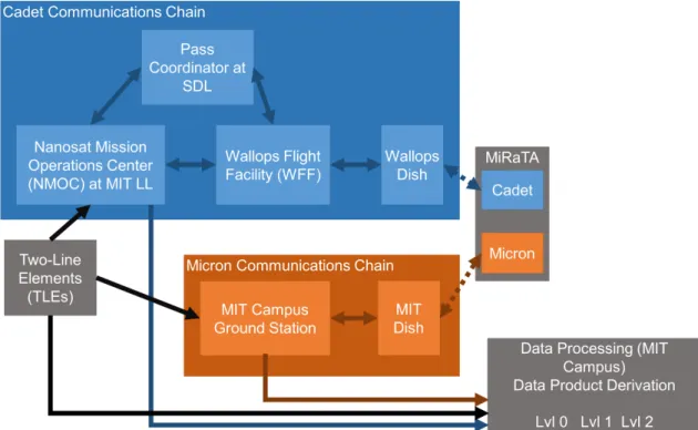
in MiRaTA is similar to the MicroMAS-1 one. For MiRaTA, we have added the Micron communications chain. . . 32 2-8 MiRaTA spacecraft science maneuver. The green is the payload and
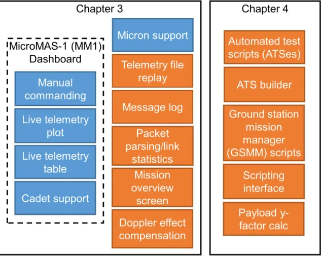
the blue is the spacecraft bus. The triangles indicate relative fields-of-view and direction of the payload instruments (GPS, GPSRO antenna, and radiometer).[8] . . . 33 2-9 Collection of the tasks that run in the FSW. . . 35 2-10 Nominal spacecraft modes.[18] . . . 37 3-1 An overview of the functionality of Dashboard. All functionality shown
is present in MiRaTA’s Dashboard. Orange boxes show where the author made significant contributions. . . 41 3-2 List of sample commands. . . 42 3-3 Sample command form. . . 43
3-4 Dashboard’s main screen. This is also the telemetry overview page. . 44
3-5 Sample telemetry plot. . . 45
3-6 Message log, with two of the message options selected. . . 46
3-7 Mission summary page (showing random data). . . 47
3-8 Dashboard architecture. . . 48
4-1 Radiometer TVAC GSE equipment diagram.[22] . . . 52
4-2 Radiometer TVAC GSE GUI for controlling the reflector’s motor.[22] 53 4-3 Code layout of the TVAC GSE GUI.[22] . . . 54
4-4 Payload y-factor calibration page in Dashboard. . . 55
4-5 MicroMAS-1 payload calibration set up.[9] . . . 56
4-6 ATS concept. . . 57
4-7 GSMM script concept. . . 58
4-8 ATS creation tool main page. . . 59
4-9 Form to add a command to an ATS. A similar form is used to add a telemetry checkpoint to an ATS. . . 60
4-10 Simple raw ATS file sample. ATSes are formatted as Javascript Object Notation (JSON). . . 61
4-11 An operator can choose an ATS to run from the ATS tab. . . 62
4-12 An operator can choose a GSMM script to run from the GSMM tab. 63 4-13 ATS summary before execution. . . 63
4-14 GSMM script summary before execution. . . 64
4-15 ATS output. . . 64
4-16 Dashboard block diagram with the addition of the GSMM subsystem. 65 5-1 MicroMAS-1 ground station diagram, repeated from Chapter 2 for reference.[9] . . . 74
5-2 MicroMAS-1 software and data processing pipeline.[9] . . . 75
5-3 Cadet downlink/uplink chain. . . 76
List of Tables
2.1 Types of environmental tests conducted on MiRaTA. . . 20 5.1 Types of functional tests conducted on MiRaTA. . . 72
Chapter 1
Introduction
The purpose of this thesis is to demonstrate process improvement for testing and mission operations for CubeSats. Although this work was created specifically for the MiRaTA mission, the general concepts can be applied to other CubeSats as well.
1.1
CubeSats and Weather Sensing
Remote sensing enables scientists to measure properties of the Earth, such as surface temperature and atmosphere composition, from afar. One important type of Earth observing remote sensor is the microwave radiometer; radiometers currently in orbit around the planet capture important observational data as input for weather forecast-ing models, which generate our day-to-day weather forecasts. Therefore, improvforecast-ing the quality, global coverage, and frequency of microwave radiometer data is of direct interest to scientific organizations such as the National Oceanic and Atmospheric Administration, NASA, and society at large. One way to accomplish this goal is to improve the development process and on-orbit operations of spacecraft used to carry and operate radiometers.
Currently operating weather satellites are typically monolithic structures that host many different types of sensors.[6] These satellites are very large in size (thousands of kg), with high development costs in time (over ten years) and money (hundreds of millions to billions of dollars). Due to their expensive and monolithic nature, these
satellites also have a high impact of failure. In addition, their revisit period is too long (from a minimum of 4-6 hours to up to 2 weeks over the same ground site) for what would be necessary to improve severe weather tracking (15-30 minutes).[6]
Instead of using large satellites to hold many sensors, an alternative solution is to build many small satellites (also known as CubeSats or nanosatellites), each holding their own remote sensing payload.[6] Each satellite would have costs in the million-dollar range, with a development time of 2-3 years. Since each satellite is relatively cheap and has only one payload, if several are built, the failure impact is low. To achieve a low revisit period (15-30 min), a constellation of small satellites could be flown. This alternative satellite development paradigm is currently being undertaken at MIT Lincoln Laboratory (MIT LL) in collaboration with the MIT Space Systems Lab (MIT SSL); many other universities are developing and flying CubeSats as well. Several CubeSat programs from MIT LL/MIT SSL have already flown. The Micro-sized Microwave Atmospheric Satellite-1 (MicroMAS-1) was the first Cube-Sat launched by MITLL/MIT SSL, in March 2015. MicroMAS-1 was able to perform a successful checkout of its spacecraft systems; however, its transmitter eventually failed a week into the mission, and no payload data was successfully received.[6] The Microwave Radiometer Technology Acceleration spacecraft (MiRaTA) All of these radiometer spacecraft have similar size (3U, 30 cm x 10 cm x 10 cm) and power specifications ( 10 watts); each has a different radiometric payload, however.[6] The MiRaTA spacecraft is of interest to this work, and will be discussed further.
1.2
MiRaTA and MicroMAS-1
Figure 1-1: MiRaTA spacecraft.[26]
The MiRaTA spacecraft is comprised of several printed circuitboards (PCBs) con-nected through a common header; on each circuitboard there are several types of sensors (such as temperature and voltage sensors) as well as connections to devices (such as reaction wheels and radios). MiRaTA also has a main microcontroller that coordinates interactions with each device; the microcontroller runs a lightweight real-time operating system which uses a cooperative scheduler to make sure tasks are executed properly. External input to MiRaTA comes in the form of packets; these packets can be sent via radio or via serial. MiRaTA has two types of radios, the Micron radio (used for live commanding) and the L3 Cadet radio (used for rapid data downlink); both radios operate in the ultra-high frequency (UHF) range.
MiRaTA utilized a good deal of code from MicroMAS-1. One software tool that was used on MicroMAS-1 and adapted for MiRaTA is Dashboard[19], an application
that can interface with ground station hardware to talk to the satellite. Dashboard was used to both test the spacecraft on the ground and communicate with the space-craft while it was orbiting Earth. Its user interface provided a simple command form for issuing packets to the satellite, as well as a few different displays of telemetry from the latest packets received from the spacecraft. Dashboard also saves data it receives from the satellite, for later processing. Dashboard played a crucial role in testing the MicroMAS-1 satellite, as it is the primary way of commanding the satellite and viewing its state.
In order to ensure that a satellite will operate when it is launched into space, a satellite must undergo a gamut of electrical, software, and environmental testing on the ground. The bare minimum for the electrical and software testing is manual verifi-cation of each parameter under test, which was the strategy used for the MicroMAS-1 mission. Most manual tests involved looking at a piece of data from a particular sensor and seeing if it made sense given the current spacecraft environmental conditions.
These manual tests have several flaws, stemming from their very human-intensive nature. Since each test needed to be run by an engineer, tests were subject to variabil-ity such as timing between commands, errors in command sequence or parameters, or failure to properly document the command sequence used. The tests were also very repetitive, which can be boring for the test engineers, and also led to a disinclination to run tests more often than the minimum necessary to ensure the spacecraft was functioning at a basic level. Since the spacecraftâĂŹs state was constantly in flux (due to changing software, hardware, and environments), ideally testing would be done frequently to ensure operation of both new and old features.
During the MicroMAS-1 mission, Dashboard was also used as the primary way of interfacing with the satellite. Dashboard did not have capabilities beyond the bare minimum (command and view of telemetry), which led to some operational difficul-ties while using Dashboard during the mission. For example, often, ground station engineers would need to issue a sequence of predetermined commands. Unfortunately, Dashboard at the time offered no way to define and verify these commands prior to sending them, which resulted in engineers having to manually fill in the command
form each time, in a specified order, every time they wanted to command the space-craft to do something. This introduces a great risk of human error. The difficulty of issuing these commands was compounded by the short time that the satellite was in communication at a given time with a ground station, creating a source of stress for the ground station engineers. Eventually software workarounds were made, but they were ad-hoc.
Automated testing and commanding provides another alternative to manual test-ing, and addresses concerns related to the manual testing approach. An automated test is comprised of the same command sequences and telemetry checkpoints as de-scribed for the manual test, but would be issued/checked by software rather than by human operators. Automated testing would allow for a test to be run many times over, reducing human error and cognitive load during testing. The repeatability of an automated test would also ensure that any changes in the results of a test were due to either environmental changes, hardware changes, or software changes (rather than variance in how the test was administered). Finally, mission operations would benefit from an automated approach, as operators would not need to worry about acciden-tally missing a command, or entering in a wrong command. Automated commanding gives mission operators a way to carefully plan out what command sequences would be issued while the spacecraft is reachable from the ground station.
In Chapter 2, we discuss testing and mission operations of a spacecraft, the Mi-RaTA mission, and the MicroMAS-1 mission. In Chapter 3, we present the basic capabilities of Dashboard. In Chapter 4, we cover our approach to building testing / automated commanding systems for MiRaTA. In Chapter 5, we discuss the perfor-mance of the MiRaTA systems as compared to the MicroMAS-1 systems and suggest avenues for future work.
Chapter 2
The MiRaTA and MicroMAS
CubeSat Missions
As background for this thesis, we provide a brief overview of general concepts relating to the testing and operations of satellite missions. We then describe the MiRaTA mission, with a focus on its hardware and software components. Finally, we briefly discuss the MicroMAS mission.
2.1
Testing and Mission Operations
2.1.1
Qualification and Acceptance Testing
All spacecraft must go through a battery of tests before they are approved for launch by the company that coordinates launches of spacecraft (a launch service provider). These tests (also known as acceptance tests) emulate the conditions the spacecraft will be subjected to during launch and after deployment in space.[5] They help verify spacecraft build quality, integrity, and ensure that the spacecraft will be able to be launched properly. In addition to the LSP’s tests, teams also conduct their own tests to check spacecraft workmanship and functionality; tests to check if the spacecraft will meet design parameters are called qualification tests.[5]
Table 2.1: Types of environmental tests conducted on MiRaTA.
Test Conditions Component lvl Subassembly lvl SV lvl
TC Vacuum or oven X X
TB Vacuum X
Vibration Room temp/pressure X X
EMC Room temp/pressure X X
Functional Vacuum or room X X X
An X indicates that at least one of that type of test was performed on MiRaTA. Component/subassembly/space vehicle examples: A component would be something like a battery, subassembly means the entire power system, and space vehicle means the entire spacecraft.
which will be launched is called the flight model (FM); usually the FM is subjected to the bare minimum of tests needed to verify that the spacecraft is operational, in order to avoid causing harm to the spacecraft while doing testing. A structural/ther-mal model (STM) replicates the physical structure and therstructural/ther-mal properties of the spacecraft but without functional components; building an STM is much cheaper and easier than building a full spacecraft and allows the team to do rigorous physical testing without risk of harming the FM. The engineering model (EM) is a replica of the FM, but is used on the ground for development and functional testing much more than the flight model; for instance, on MiRaTA, the EM was used for virtually all of software development. During mission operations, the EM can be used as a way to verify expected spacecraft behavior, before sending commands to the actual FM in space.
Figure 2-1: MicroMAS-1 spacecraft in a thermal vacuum chamber.[9]
Types of tests that a spacecraft undergoes include, but are not limited to:
• Thermal cycling (TC): Repeatedly expose the spacecraft to a cycle of cold temperatures, then hot temperatures.[3] Thermal cycling causes expansion and contraction of components, another potential source of stress for the spacecraft. Workmanship issues (how well components are assembled) can be exposed in this test.
• Thermal balance (TB): Makes sure that the spacecraft does not heat up or cool down too much while in vacuum; the spacecraft temperatures are compared to the thermal model for verification.[3] This test is necessary because heat transfer is different in space versus on Earth.
• Thermal vacuum (TV or TVAC): Expose the spacecraft to high vacuum and extreme temperatures, to emulate flight conditions.[5]
• Vibration: Vibration tests vibrate the spacecraft in a way that emulates the type of vibrations that may arise during launch.[5] Different types of vibration profiles are used, such as sinusoidal vibrations and random vibrations.[1]
• Shock: Shock tests subject the spacecraft to sudden motion.[1]
• Electromagnetic compatibility (EMC): EMC tests check for excessive elec-tromagnetic (EM) emissions created by the spacecraft, and also determine if the spacecraft is susceptible to external EM interference.[2]
• Functional: Functional tests check if the spacecraft can execute all of the functions required of it to complete the mission. These are defined by the team developing the spacecraft.
2.1.2
Mission Operations
After satisfactory qualification/assurance testing, the spacecraft is integrated into the launch vehicle by the LSP. Some time after that, the spacecraft is launched into orbit, at which point mission operations begins. Mission operations is the point at which the spacecraft is remotely controlled by operators. There are two main phases to mission operations: in-orbit testing (also called early orbit checkout) and nominal operations. The purpose of in-orbit testing is to verify that the spacecraft is operating as ex-pected in space; this includes telemetry/radio communications verification, payload checkout, calibration, and some other functional tests.[27] Once in-orbit testing has been completed, the mission enters nominal operations; for MiRaTA, this involves collecting science data.
In order to communicate with the satellite, the spacecraft operators must utilize a ground station. A ground station contains the radio frequency (RF) equipment and software to be able to encode and decode information to/from the spacecraft, in addition to any networking/software needed for the operators to connect to the ground station hardware (if the operators are remote).[27] Communications with the satellite can only occur when the satellite is visible from the ground station; the period of time the satellite is overhead is called an overpass. For MiRaTA, the overpass durations are no longer than 10-12 minutes.
Figure 2-2: The horizontal coordinate system.[13]
The satellite’s position relative to the ground station is typically specified in the horizontal coordinate system (as shown in Figure 2-2).[13] In Figure 2-2,
• 𝑁𝐸𝑆𝑊 are the cardinal directions (north, east, south, west), which defines the horizontal plane.
• 𝑋 is the observer (the ground station in our case). • 𝑅 is the satellite.
• 𝑅′ is the projection of 𝑅 onto the horizontal plane (also called the local horizon).
• 𝑎 is the altitude of 𝑅, or the angle between 𝑋𝑅 and 𝑋𝑅′.
• 𝐴 is the azimuth of 𝑅, or the angle between 𝑋𝑁 and 𝑋𝑅′; it increases from
north to east.
Information about the satellite’s orbit is stored in the two-line element (TLE) format.[17] TLEs describe the orbit of a satellite, and are generated periodically by NORAD (North American Aerospace Defense Command).[17] To use TLEs, an operator feeds them into an orbit propagator, which calculates the path of a satellite (also called the ground track) and when the satellite will pass over the ground station; the propagator then displays the results via a graphical user interface. GPredict1 is
1
an open-source piece of software that is commonly used for this purpose; there is also a website called n2yo.com that will also display satellite ground tracks.
Figure 2-3: MiRaTA’s ground track shown in n2yo.com.[28] Imagery from Google Maps.[15]
Another important variable for the operator to keep in mind during mission oper-ations is the effect of Doppler shift on satellite communicoper-ations. Doppler shift is the phenomena where a receiver (e.g. a ground station) of a signal generated by a moving source (e.g. a satellite) will observe a change in frequency of the signal; this change depends on the relative velocity of the source and the receiver.[14] If the source is moving towards the receiver, then the receiver will perceive a higher-frequency signal than what the source is actually emitting; if the source is moving away from the receiver, then the receiver will perceive a lower-frequency signal. Depending on the bandwidth (the understandable frequency range) of the receiver, Doppler shift can make communications useless. Ground stations often implement Doppler correction measures to account for Doppler shift; for instance, if a satellite is traveling towards a ground station, the ground station will emit signals which are lower than the expected receiver frequency of the satellite so that, when the signals arrive at the satellite, they are at about the proper frequency. The appropriate Doppler correction is calculated using the spacecraft TLE and the ground station location latitude/longitude/eleva-tion.
2.2
MicroMAS-1
Figure 2-4: MicroMAS-1 model.[9]
The MicroMAS-1 mission was the first joint CubeSat mission between the MIT Space Systems Laboratory (SSL), MIT Lincoln Laboratory, and the University of Mas-sachusetts at Amherst.[11] The payload of MicroMAS-1 was a passive scanning mi-crowave radiometer; it had a scanner assembly that rotated the payload at about 0.8 Hz.[11] MicroMAS-1 was delivered to the International Space Station in 2014 and was deployed in March 2015; unfortunately, after one week, the spacecraft suffered a transmitter fault.[9]
The small MicroMAS-1 team had to design many procedures, build avionics boards, and write flight/ground software code all from scratch. This understandably led to some sub-optimality in MicroMAS-1 testing and mission operations procedures, as the team was stretched thin and simply did not have enough time to complete the necessary work. MiRaTA, which has the advantage of relying upon the vast body of
work done by the MicroMAS-1 team, was able to improve upon some of the issues, as described in Chapter 5.
2.2.1
Mission Operations
Some background on the specific configuration for MicroMAS-1 mission operations is useful for understanding MiRaTA’s set-up, as several aspects remained the same through both programs. The high-level block diagram is shown in Figure 5-2.
Figure 2-5: MicroMAS-1 ground station diagram.[9]
The process of communicating with the satellite during MicroMAS-1 operations went as follows:
1. The mission planning team at LL (in Massachusetts) would figure out what the goal of the next overpass was. For instance, confirm that a particular subsystem is working.
send during the overpass, and notify the mission command team at SDL (in Utah).
3. The mission command team would issue commands and receive telemetry re-motely through the dish at the Wallops Flight Facility (in Virginia).
4. Any data would also arrive at MIT campus, where it would be processed by the data analysts.
As a result of data analysis, multiple data products are produced. These data products are described by the NOAA processing levels:[24]
• Level 0: Unprocessed spacecraft telemetry.
• Level 1: Instrument-specific datasets that have been timestamped and include raw unprocessed science data, with other information like data quality measure-ments and calibration coefficients.
• Level 2: Contains geophysical variables derived from the Level 1 data, with the same resolution and locations.
2.3
MiRaTA
The MiRaTA spacecraft, the primary focus of this thesis, is the result of a collabora-tion between the MIT STAR (Space Telecommunicacollabora-tions, Astronomy, and Radiacollabora-tion) Laboratory, MIT Lincoln Laboratory, The Aerospace Corporation, the University of Massachusetts, and Utah State University.[7] The goal of the MiRaTA mission is to validate a passive microwave radiometer (MWR) and a GPS radio occultation (GP-SRO) instrument, and also use a new approach to CubeSat radiometer calibration using GPSRO measurements.[7] The planned mission duration is 90 days long.[12]
Figure 2-6: MiRaTA spacecraft, expanded so some components are visible.[8]
2.3.1
Payload
The microwave radiometer is a tri-band, 10-channel sensor that provides temperature, humidity, and cloud ice measurements; its three frequency bands are 52-58, 175-191, and 206-208 GHz.[7]2 A microwave radiometer works by measuring the thermal
radi-ation (brightness temperature) emitted by objects of interest (e.g. clouds, the Earth’s surface, vegetation) over various frequencies; the response received by the radiometer versus the frequency of the response is used to create an absorption profile.[23] This absorption profile can then be compared to known absorption profile characteristics to figure out various aspects of climate data (such as the temperature profiles MiRaTA
hopes to obtain). Microwave radiometers report brightness in raw digital numbers (also called DNs or counts); it is thus important to calibrate the radiometer so that one knows what counts correspond to what temperature. Calibration is typically done by repeatedly pointing the radiometer at a hot target, then a cold target; these targets are usually blackbodies, which means they have a known relationship between their temperature and the amount of microwave energy they emit. On orbit, calibration must be done frequently in order to correct sensor drift. Using bulky blackbodies is unfortunately not an option for small CubeSats, which means alternative calibration methods (such as the one being pioneered by MiRaTA) must be used.
The GPSRO instrument is called the Compact TEC (Total Electron Count) / Atmosphere GPS Sensor (CTAGS), and is based on a GPS receiver (OEM628) plus a patch antenna array.[8] 3 GPSRO measurements have been demonstrated to have
the capability to create temperature profiles in the upper troposphere / lower strato-sphere that approach 0.1K accuracy.[7] MiRaTA’s radiometer calibration approach will leverage GPSRO measurements of the Earth’s limb, which is the atmosphere at the visual edge of the Earth. The calibration approach will also use a noise diode, which serves as a source of calibration signal; it itself will be calibrated using GP-SRO measurements. Together, using the noise diode and GPGP-SRO, MiRaTA is able to avoid the use of the aforementioned bulky blackbody targets for calibration.[7] Because MiRaTA does not do the typical calibration via external targets, MiRATA has no active scanning mechanisms, simplifying the spacecraft structure.[26]
The final components of the payload are the Intermediate Frequency Processor (IFP) and Payload Interface Module (PIM). The IFP does digitization and signal processing on the incoming radio frequency (RF) signal. The PIM coordinates the actions of the payload sensors, and serves as an interface between the bus and the payload.
2.3.2
Bus
The operation of the MiRaTA payload is supported by the spacecraft bus, which is a collection of boards and components that make up the rest of the spacecraft; it includes, among other components, two radios, a microcontroller, a power subsystem, and an attitude determination and control system (ADCS). The design of the bus carries over many lessons learned from MicroMAS-1 and uses many of the same com-mercial off-the-shelf (COTS) components.[26] The COTS components are integrated together using several custom-designed boards. Together, the bus and the payload fit in a standard 3U CubeSat configuration, which is 10 cm x 10 cm x 34 cm with a mass of around 4.5 kg.[12] 4
Power
MiRaTA’s power5 is provided by the Clyde Space6 Electronic Power System (EPS),
a Clyde Space battery, and Clyde Space double-deployed solar panels.[7] The EPS provides the spacecraft bus regulated sources of 3.3V and 5V power, as well as a connection to the battery (7-8V depending on charge). All lines also contain over-current protection; when the EPS’s microcontroller detects an overover-current condition, the output lines are disconnected from the rest of the spacecraft bus.[10] The solar panels connect to the EPS through a battery charge regulator (BCR), which then connects to the battery for charging.
External to the EPS are a handful of power switches (called power distribution units or PDUs). These PDUs control power to each individual sensor/subsystem and can be toggled with the microcontroller.
4MiRaTA structures were worked on by Tim Cordeiro and Dave Toher.
5MiRaTA’s power subsystem was worked on by Annie Marinan and Ayesha Hein. 6https://www.clyde.space/products
Communications
MiRaTA sports two ultra-high frequency (UHF) radios, one for data downlink and one for commanding.7
The first is called the Cadet-U radio, developed by L-3 Communications and the Space Dynamics Laboratory (SDL). It is the way payload and spacecraft data is downlinked from the spacecraft, due to its high downlinked data rate ( 3.0 Mbps) and large amount of internal storage.[20] It operates in the UHF range at around 450-460 MHz; in order to communicate with it, we use the NASA Wallops ground station coupled with SDL’s SATRN and Titan software.[20, 8] The Cadet has a "store-and-forward" architecture, which means that the radio collects data from the spacecraft in its first-in-first-out buffer (which we call the FIFO), and the operators on the ground must request particular subsets of the data in the FIFO; the Cadet cannot respond with real-time data.[20]
The second radio on board MiRaTA is called the Micron radio, and is based on a Planet UHF design which uses the CC1110 radio transceiver.[21] Since it can respond in real time (unlike the Cadet), it is used as the primary commanding radio. Its ground station is based on MIT’s campus.[8]
7MiRaTA’s communication systems were worked on by Greg Allan, Mic Byrne, Myron Lee, Julian
Figure 2-7: MiRaTA ground station diagram. The Cadet communications chain in MiRaTA is similar to the MicroMAS-1 one. For MiRaTA, we have added the Micron communications chain.
ADCS
The ADCS is made of a complement of sensors and actuators.8 The bulk of the ADCS
consists of the MAI-400 from Adcole Maryland Aerospace[4]. It contains a 3-axis magnetometer, two IR Earth Horizon Sensors (IREHS), three electromagnets (also called torque rods), three reaction wheels, and an ADACS computer.[4] In addition to the MAI-400, MiRaTA also has an inertial measurement unit (IMU) and another EHS.[7]
8The ADCS subsystem for MiRaTA was worked on by Zack Lee, Weston Marlow, and Adam
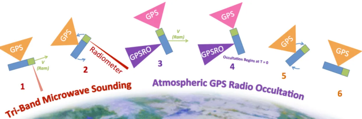
Figure 2-8: MiRaTA spacecraft science maneuver. The green is the payload and the blue is the spacecraft bus. The triangles indicate relative fields-of-view and direction of the payload instruments (GPS, GPSRO antenna, and radiometer).[8]
All of these sensors and actuators are used to perform several spacecraft move-ments, critical to mission success. The first ADCS mode to run is detumble, which stabilizes the spacecraft from tumbling after deployment. In nominal operations, the ADCS will also execute pitch-up and pitch-down moves, which moves the bus in such a way that the payload can scan the Earth’s limb. These up and pitch-down moves are a part of the spacecraft’s calibration maneuver (also called maneuver mode), depicted in Figure 2-8; it lasts about 10 minutes.[8]
Other Components
Other components of note include:
• A set of resistive temperature detectors (RTDs) for monitoring the temperature of various components.
• An oscillator to serve as the spacecraft’s sense of time/clock (also called avionics elapsed time or AET).
• A flash chip for storage of multiple flight software images.
• A set of thermal knife drivers (TKDs) which, when fired, deploy the solar panels.
The spacecraft motherboard is a Pumpkin CubeSat motherboard.[7] Custom-built boards interface with the COTS components, and form the backbone of the avionics
stack. These boards are called the Top Interface Board (TIB), which interfaces with the Cadet radio; the Bottom Interface Board (BIB), which interfaces with the MAI-400; and the Micron Motherboard (MMB). The format of the boards follows the CubeSat Kit PCB Specification.9
Microcontroller and Flight Software (FSW)
MiRaTA’s onboard microcontroller is a PIC24 running the Salvo Real Time Operating System (RTOS).[25] Salvo was chosen for its extremely low memory requirement, and was previously used on MicroMAS-1.[25, 11] The flight software (FSW) is written in C.10
Salvo is a purely event-driven, stack-less cooperative multitasking RTOS11.[25] A
Salvo program is broken into a main program and various tasks. The main program typically runs setup code (running initialization code for subsystems, for instance), then runs the Salvo scheduler forever in a while loop. The scheduler then runs tasks according to priority (there are 16 levels of priority available in Salvo); tasks that share the same priority run in round-robin fashion.[25] Since Salvo is cooperative, each task must manage task switching; this means that when a task is waiting or done, the task must explicitly yield control to the scheduler, otherwise the operating system can become stuck. Because each task controls when it switches, Salvo does not need to keep a per-task stack; it merely needs to save registers on a task switch. Another important part of the OS are interrupt service routines (ISRs), which are pieces of code that handle external events (such as data becoming available from a sensor). An ISR can interrupt any task; once the ISR is finished running, control is returned back to the task that was interrupted.
9
Available at http://www.cubesatkit.com/docs/CSK_PCB_Spec-A5.pdf
10Some code was taken from MicroMAS-1’s FSW, which was primarily written by Ryan Kingsbury;
other contributors include Kris Frey and the author. The FSW for MiRaTA was primarily written by Kit Kennedy, with contributions by Julian Mendoza, Joe Kusters and Patrick Kage.
11Salvo is very different in concept from Linux, MacOS, or Windows, all which are pre-emptive
multitasking operating systems. In a pre-emptive OS, tasks can interrupt each other, with the assumption that an interrupted task will resume later.
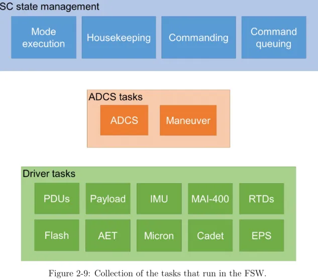
Figure 2-9: Collection of the tasks that run in the FSW.
The FSW consists of all the tasks listed in Figure 2-9.
• Device drivers: At the lowest level, all subsystems/sensors have their own driver, which is code that handles communication with the subsystem/sensor. Drivers issue commands to their respective subsystems, collect data, and moni-tor their subsystems for faults/errors. Each driver is structured in a loop which executes forever while the processor is running. Most drivers also contain ISRs to handle the many communication interfaces used on the spacecraft; examples include SPI (Serial Peripheral Interface Bus), I2C (Inter-Integrated Circuit), and UART (Universal Asynchronous Receiver-Transmitter). Device functional-ity can be enabled or disabled by either the special function tasks or the high level tasks.
• ADCS tasks: These tasks control the execution of complicated routines. The ADCS task manages the algorithmic aspects of moving the spacecraft in certain ways; it executes spacecraft detumbling and pitch-up/down motions. The ma-neuver task is in charge of managing the ADCS task state so that the payload can take radiometer and GPSRO measurements, as shown in Figure 2-8. • Spacecraft state tasks: The mode execution task keeps track of what mode
the spacecraft is in, and handles both autonomous and manual state transitions; nominal modes are shown in figure 2-10. The housekeeping task keeps track of all of the faults that accumulate from the different subsystems on the spacecraft, and also keeps track of the frequency of code execution and the last time the spacecraft heard from a ground station. The commanding task handles the interpretation of commands from the ground, and can command a transition to a modes or turning devices on and off. The command queuing task keeps track of commands to be executed in the future; when it comes time to execute queued commands, the command queuing task issues them to the commanding task.
Spacecraft Modes
There are a few special modes that the spacecraft enters; nominal operational modes are discussed below. When the microcontroller boots up (either through deployment or through a spacecraft reset), the spacecraft is in "not initialized" mode. It then autonomously and immediately moves to "inhibit mode" where the spacecraft waits for some time. After "inhibit mode", the spacecraft autonomously moves to "deploy mode", which fires the TKDs, thereby deploying the solar panels. After that, the spacecraft autonomously enters "safe mode", which indicates that the spacecraft is ready to begin mission operations. The spacecraft can then be manually commanded into the modes listed in Figure 2-10 below. The only one of the previously-described modes that the spacecraft can return to (without a spacecraft reset) is "safe mode", which the spacecraft can autonomously transition to if there are too many faults; in
transitioning to safe mode, all non-essential devices are turned off.
Figure 2-10: Nominal spacecraft modes.[18]
The five listed modes are the nominal operational activities for MiRaTA, and are mutually exclusive.[18] Maneuver mode is as described in Figure 2-8. The slew mode involves moving the spacecraft from one attitude (orientation) to another. Recharge mode corresponds to the ADCS suntracking mode, which charges the batteries with solar energy. Downlink mode corresponds to when the spacecraft is commanded to downlink data through the Cadet radio. Idle mode is the mode where the spacecraft is doing nothing but maintaining a radiometer nadir pointing attitude, Local Vertical Local Horizontal (LVLH); this means that the spacecraft is oriented parallel to Earth’s surface.
Software Development
MiRaTA uses the Git12version control system. All code resides in the same monolithic
repository, so that the team knows that a particular version of the flight software will
12
Chapter 3
Dashboard: Software for Command
and Data Handling
3.1
Introduction
Dashboard1 serves as a way for human operators to communicate with the satellite,
and also observe the state of the satellite. Dashboard has the capability to interface with several types of ground stations, up to the operator’s choosing. Using Dash-board’s web interface, operators can send commands to the spacecraft, and observe telemetry in real-time. In this chapter, we cover the basic functionality of Dashboard: its software architecture, as well as some screen shots. The automated testing/com-manding features will be discussed in the next chapter. Note that all screen shots used here and in the next chapter use randomly generated data.
Originally, Dashboard was created for the MicroMAS-1 mission, to assist in com-manding and debugging the spacecraft telemetry. It was also used as a part of MicroMAS-1 mission operations, which will be discussed in Chapter 5.
Dashboard’s functional requirements are as follows2:
1. Dashboard must support real-time (live) communications with the spacecraft
1Dashboard was originally written by Ryan Kingsbury, with many modifications from Kit
Kennedy, the author, Patrick Kage, and Erik Thompson.
2Many of these are the result of MicroMAS-1 experiences; specific suggestions were made by
via the Micron radio, the Cadet radio, and a USB-serial link.
2. For each link, Dashboard must allow for commanding on that link, and inter-preting telemetry packets from that link.
3. Dashboard must be able to display real-time telemetry from the spacecraft. 4. Dashboard must be able to facilitate live-debugging of the spacecraft and its
constituent components.
5. Dashboard must provide a time-tagged command log file, to record the com-mands sent during a session.
6. Dashboard must provide a time-tagged telemetry log file, to record the telemetry sent during a session.
7. Dashboard must be operator friendly: minimize operator error; provide easy-to-use tools.
8. Dashboard must provide a method for Doppler effect compensation.
As context for this chapter and the next, Figure 3-1 shows the specific Dashboard functionality that will be discussed.
Figure 3-1: An overview of the functionality of Dashboard. All functionality shown is present in MiRaTA’s Dashboard. Orange boxes show where the author made significant contributions.
3.2
Dashboard User Interface
Dashboard is started in one of many modes depending on what the operator would like to do. The most frequently-used options are as follows:
• Serial: Command the spacecraft over USB-serial. • Micron: Command the spacecraft via Micron radio. • Cadet: Command the spacecraft via Cadet radio.
• File: A special mode where Dashboard reads in a telemetry file and displays the telemetry to the operator; not used for commanding.
• Doppler: Prior to Dashboard sending a spacecraft command, Dashboard will calculate the proper uplink frequency to transmit the command at to compen-sate for the Doppler effect.
3.2.1
Commanding
Figure 3-2: List of sample commands.
In order to command the spacecraft, an operator will visit the command page and can click on a command under the "Available commands" heading. CMD_EXAMPLE_1 in Figure 3-2 is an example of such a command.
Figure 3-3: Sample command form.
When clicking on one of the commands in the command list, a form will appear with fields corresponding to the packet’s schema. On clicking submit, a packet will be generated and sent to the spacecraft.
3.2.2
Telemetry
Figure 3-4: Dashboard’s main screen. This is also the telemetry overview page.
When first opening Dashboard in the browser, the operator is shown a summary of the telemetry packets received so far. The left pane of all pages (including this one) is a collapsible navigation bar, shared between all Dashboard pages. The top-left is a live updating section that shows useful information such as the type of link-mode (serial, Micron radio, or Cadet radio), the time, the current command sequence number, number of packets received, number of packets sent, and number of packet errors.
The operator can click one of the buttons at the top of the page under "Available packets" to take them to the telemetry packet that they are interested in. For each packet, the operator can choose to either view the recent history of packets (the last 10, 50, or 100 packets received); see a live-updating table containing the packet data; or do a live plot of the fields in the packet.
Live Plotting
In order to do a live plot of a packet, the operator should click the "live plot" button and select how many data points and what fields to plot.
Figure 3-5: Sample telemetry plot.
Figure 3-5 shows an example of a live plot; it uses the Highcharts Javascript library.3 The live plot feature is useful during testing and debugging, for observing
transient effects in telemetry.
Message Log
Figure 3-6: Message log, with two of the message options selected.
A helpful debugging tool is the message log, which keeps track of interesting events as they occur. It is most often used with the "cmd" and "tlm" options enabled, which tracks the interleaving of commands as they are sent and telemetry received in response. Other especially useful messages include "dev", which prints when devices on the spacecraft are turned on and off, as well as "fault", which prints when the spacecraft generates a fault message.
Mission Summary
Figure 3-7: Mission summary page (showing random data).
Unlike the other telemetry views, this page was created with mission operations in mind. It contains the spacecraft state tracked by Dashboard’s backend. By looking at the leftmost column, the operator can tell at a glance what devices are on, what state the spacecraft is in, and what temperatures all the components are at currently. In the middle column, we track the command numbers, the FIFO state (the Cadet radio’s internal storage), the conversion between three onboard time systems, and the spacecraft telemetry generation rate. In the right column, we see a message log consisting of the incoming telemetry packets and outgoing commands.
Other Telemetry Views
In addition to the above views, Dashboard offers several other debugging tools:
• Link stats: Shows bytes received and bytes sent, as well as other statistics corresponding to packet framing and deframing.
• Parser stats: Keeps track of how many packets of each type have been parsed, in addition to parsing errors.
• Telemetry file replay: Allows a telemetry file to be loaded into Dashboard. An operator can then select specific portions of the file to inspect, for quick sanity checking of a previous logfile.
3.3
Dashboard Architecture
Dashboard consists of two main parts: the data-processing backend, and the operator-facing frontend. It is written in Python 2.7.4 The library used to establish connections
is Twisted5, a networking engine. Flask6 is used to serve pages to the browser, and
templates were created using Jinja27.
Figure 3-8: Dashboard architecture.
4
https://www.python.org/
5https://twistedmatrix.com/trac/ 6http://flask.pocoo.org/
3.3.1
Command Transmit Path
In order to transmit a command, a user goes to the command form page in the Dashboard GUI and fills out the fields. On form submission, the packet builder is called, generating a serialized form of the packet. This serialized form is then passed on to the logger and the packet framer; the logger saves the packet to disk, and the packet framer adds on additional bytes to the beginning of the packet (a packet header) depending on what type of link we are using (Cadet radio, Micron radio, or serial). After packet framing, the packet is passed to the Twisted protocol layer, which sends the packet to the ground station. Finally, the ground station transmits the packet to the satellite.
3.3.2
Telemetry Receive Path
The telemetry receive path is the inverse of the command transmit path. The space-craft transmits RF energy, which is received by the ground station. The ground station then demodulates the signal and digitizes it before sending it to Dashboard via the Twisted protocol layer. The bytes are then sent to a deframer, which searches for sentinel bytes signaling the start of a packet frame. After a frame is found, the header is stripped off and the packet is sent to the packet parser. The packet parser checks the deframed data against the packet specifications, and if it matches one of the packet specifications, sends the packet to Dashboard’s internal storage and also logs the packet to disk. After parsing, the packet data is then available in any of the telemetry views.
Chapter 4
Software Development for Spacecraft
Testing and Mission Operations
In this chapter we discuss some of the work involved in testing and operating MiRaTA. We briefly cover interfaces for testing of the payload. The bulk of the chapter covers the development of the automated testing system for Dashboard.
4.1
MiRaTA Payload Testing Software
As covered in Chapter 2, it is important to make sure that a microwave radiometer (MWR) is properly calibrated to ensure correct correspondence between reported dig-ital numbers and temperature. Before our MWR is flown, we measure its performance in a known testing environment that replicates space conditions (a thermal vacuum chamber, or TVAC chamber). Running the calibration within the TVAC chamber requires assembling special ground support equipment (GSE).[22]
Figure 4-1: Radiometer TVAC GSE equipment diagram.[22]
On the ground, we are able to use conventional blackbody targets for calibrating our MWR; this technique is called periodic absolute calibration, or PAC.[22] As shown in Figure 4-1, a box frame was constructed to hold three blackbody targets: one hot, one cold, and one variable. The frame also held a reflector that could rotate to point at each target in turn, reflecting the radiation of each blackbody target onto the MWR in sequence. A computer was connected to the reflector motor driver (to control the motor) and a Keithley switching multimeter (for temperature sensing of the blackbody targets and motor); the computer provided a GUI (see Figure 4-2) to control and observe the state of the system.1 The GUI is written in Python, and uses
the PyQt framework.2
1The TVAC GSE GUI was originally written by Michael DiLiberto, with rewriting by the author. 2
Figure 4-2: Radiometer TVAC GSE GUI for controlling the reflector’s motor.[22]
The TVAC GSE GUI features buttons to move the reflector for testing, control radiometer data collection, and view temperature plots and statistics. In order to head off some amount of operator error, the buttons on the GUI would grey-out if clicking them would cause strange motor controller behavior.
Figure 4-3: Code layout of the TVAC GSE GUI.[22]
The first prototype of the GUI was able to plot temperature, but could be slow to update. In order to support concurrent data updating and motor control, the GUI’s backend was rewritten into several parts that did not block on each other (see Figure 4-3).
Figure 4-4: Payload y-factor calibration page in Dashboard.
The final piece of the radiometer calibration is Dashboard, which is the primary way of controlling the radiometer through testing. One of the ways the radiometer’s performance was calculated (in addition to PAC) is called the y-factor method, which allows one to calculate the noise figure and gain of a sensor.[16] For TVAC testing, a special y-factor calculation page (Figure 4-4) was written for Dashboard. It stepped the operators through the process of commanding the radiometer, moving the motor,
and collecting data. It also calculated the final y-factor results, so that the test operator could see at a glance if the radiometer was operating within parameters.
4.1.1
Results
Figure 4-5: MicroMAS-1 payload calibration set up.[9]
The TVAC GSE/GUI and Dashboard were used in September/October 2016 to run MiRaTA’s MWR TVAC testing.[8] Preliminary results from the data analysis of test-ing showed that MWR values were well within acceptable ranges for gain (accuracy) and noise equivalent differential temperature (NeDT, or precision).[8] The TVAC GSE/GUI and Dashboard commands developed for MiRaTA worked well enough
for it to be used as the basis for MWR TVAC calibration for MicroMAS-2a and MicroMAS-2b (follow-on missions for MicroMAS-1).
4.2
Automated Testing Capability for Dashboard
As a result of the team’s stressful experiences from MicroMAS-1 operations, it was decided that automated testing and commanding would be a great addition to Dash-board’s capabilities. Automated testing was developed for use in space vehicle (SV) TVAC testing during late 2016.3 Like in the previous chapter, all packets and scripts
shown are dummy versions for demonstration.
4.2.1
Scripts
There are two types of scripts that an operator can run from Dashboard. The first type is called an Automatic Test Script (ATS), and the second is called a Ground Station Mission Manager script (GSMM script). Both types of scripts are executed by the GSMM subsystem in Dashboard.
An ATS consists of a timeline of commands and telemetry check points, as in Figure 4-6.
• 0.0s: Start device A in mode 2.
• 1.0s: Check device A telemetry packet: verify that device A is on and mode is set to 2.
• 2.0s: Turn off device A.
• 3.0s: Check device A telemetry packet: verify that device A is off.
Figure 4-6: ATS concept.
When an ATS is run, the script manager within Dashboard steps through the timeline specified in the ATS and issues commands to the spacecraft and/or checks
3The automated testing system was developed by the author and Kit Kennedy, with advice from
telemetry from the spacecraft. In order to keep the system simple, the timeline specified in the ATS is relative to the beginning of when the script is executed (instead of specifying the timeline in absolute time). As an ATS executes, it keeps track of what telemetry checkpoints succeeded or failed. After an ATS is finished executing, the results are written to a log file and displayed to the user. The ATS format was intentionally kept simple, as it is intended to serve as a way to execute small device-level tests, and as a building block for more complicated behavior.
The second type of script that an operator can run is a GSMM script. Figure 4-7 shows an example of possible GSMM script behavior.
1. Execute sampleATS. 2. Wait 2 seconds.
3. Check success result of sampleATS. If it did not succeed, and the test has been running for less than one minute, go back to step 1.
Figure 4-7: GSMM script concept.
This type of script allows for more complicated control of Dashboard, as it allows the script writer to use Python to specify commanding/telemetry reading behavior. Several building blocks are built into the GSMM execution framework to enable the script writer to access Dashboard interfaces; these include the ability to execute AT-Ses, send single commands/read telemetry packets, and display data in the Dashboard GUI. A GSMM script can be as simple as a sequence of ATSes ("a script of scripts"). On the other end of the complexity spectrum, a GSMM script can also be used to issue all ground commands needed to run the spacecraft’s maneuver mode.
4.2.2
Scripting Related User Interfaces
ATS Building
ATSes are conceptually fairly simple, but their constituent commands and telemetry packet fields can be quite complex. Thus, Dashboard provides a basic ATS creation
tool that allows the script writer to fill in fields using a GUI that looks the same as the command forms used in commanding.
Figure 4-8: ATS creation tool main page.
The field "New ATS name" allows you to specify a new name for an ATS file. The field "Load ATS here" allows you to open an existing ATS for editing. If a name is not specified at file creation, the date and time is used (as shown in the line Current ATS). If the script writer wishes to save their script, they can hit the SAVE button at any point.
The table right under "Current ATS" shows a brief summary of the contents of the ATS. It lists the times, type of command or telemetry packet, and important fields that are being issued. An ATS element can also be removed via this table.
To add a command or telemetry checkpoint to the loaded script, the operator clicks one of the listed commands under "Available commands" or "Available telemetry checkpoints".
Figure 4-9: Form to add a command to an ATS. A similar form is used to add a telemetry checkpoint to an ATS.
Figure 4-9 shows the interface to add a command to an ATS. It is entirely identical to the manual command form, with the exception of the page title at the top. After hitting the submit button, the script writer is redirected back to the main ATS creation page.
1 {
2 "0.0": [{
3 "description": "Command example 1.",
4 "id": 1,
5 "name": "CMD_EXAMPLE_1",
6 "values": {}
7 },
8 {
9 "description": "Telemetry packet example 1.",
10 "id": 101, 11 "name": "TLM_EXAMPLE_1", 12 "values": { 13 "field1": [ 14 "12", 15 "DC", 16 "25" 17 ], 18 "field2": [ 19 "1", 20 "DC", 21 "2" 22 ], 23 "flag1": "0" 24 } 25 }], 26 "2.0": [{
27 "description": "Command example 5.",
28 "id": 5, 29 "name": "CMD_EXAMPLE_5", 30 "values": { 31 "flag": "2", 32 "setting": "11" 33 } 34 }],
35 "metadata": {"description": "ATS sample.", "version":"1.2"} 36 }
Figure 4-10: Simple raw ATS file sample. ATSes are formatted as Javascript Object Notation (JSON).
The raw file reflects the same amount of information visible in the ATS builder. The JSON format was chosen since it is a common data representation and, if needed, can be directly modified.
GSMM Script Building
Since GSMM scripts are just Python scripts, there is no built-in editor in Dashboard for them. However, Dashboard’s source contains a sample GSMM script for reference.
The following features are available for use in a GSMM script:
1. Requesting telemetry from Dashboard packet storage. 2. Sending a command to Dashboard.
3. Custom user-input at script execution time.
4. Execution of ATS and checking of ATS success/fail results. 5. Printing status messages to Dashboard script output page.
6. Interruptible waiting function, that allows Dashboard to gracefully kill the script if needed.
Running Scripts
The process of running an ATS and the process of running a GSMM script are vir-tually identical.
Figure 4-12: An operator can choose a GSMM script to run from the GSMM tab.
From the "ATS + GSMM Runner" screen, an operator can choose the script that they want to run. The entries of the ATS/GSMM tabs are auto-populated by the scripts available in the mirata_testing directory.
Figure 4-13: ATS summary before execution.
Figure 4-13 shows what happens when the operator clicks on an ATS name under the ATS tab. The operator is directed to an overview of the script to be run, and an execute button.
Figure 4-14: GSMM script summary before execution.
Like what happens when an ATS is clicked from the ATS tab, Figure 4-14 shows the screen that appears when a GSMM script is clicked from the GSMM tab. Instead of a script summary, the GSMM script source is just directly printed to the screen.
To actually execute the ATS or GSMM script, the operator must hit the execute button.
Figure 4-15: ATS output.
After a script (either ATS or GSMM) is executed by the operator, Dashboard automatically redirects to the script output page. Figure 4-15 depicts an example of what happens when executing the example ATS from Figure 4-13.
4.2.3
Architecture
Figure 4-16: Dashboard block diagram with the addition of the GSMM subsystem.
The code that enables the automated commanding/testing is called the Ground Sta-tion Mission Manager (GSMM), so named because this testing system would ulti-mately be used to run the MiRaTA overpasses. The orange block in Figure 4-16 represents the new code that implements the GSMM functionality. The GSMM sub-module runs in a separate process from the main Dashboard backend process, to protect the main Dashboard event loop in the case of a script programmer error. As a result, the GSMM submodule and Dashboard communicate through interprocess pipes.
When the operator accesses the test runner and clicks execute, any options (such as the name of the script) are sent to the GSMM submodule. The GSMM then executes the specified script. Any telemetry points that need to be checked go through the telemetry checker, which asks Dashboard for a telemetry packet from its packet storage; upon getting a packet, the fields are verified against the script-writer’s input. Any commands that need to be issued go through the commander, which sends a command to Dashboard for sending via the normal command transmit path.
Chapter 5
Discussion and Future Work
In this chapter, we compare MicroMAS-1 testing and mission operations procedures to MiRaTA procedures, focusing on how the work for MiRaTA in Chapter 4 helped the development process. We also discuss avenues for future work.
5.1
Comparing MicroMAS-1 and MiRaTA Procedures
As mentioned in Chapter 2, MiRaTA was able to take advantage of all of the work the MicroMAS-1 team did to help create testing and mission operations procedures. The lessons learned from the MicroMAS-1 mission informed many of the design decisions made for the MiRaTA mission. The version of Dashboard used by MicroMAS-1 only had manual commanding, the live telemetry tables, and live telemetry plotting, as described in chapter 3; we will refer to MicroMAS-1’s Dashboard as MM1-Dashboard, and the term Dashboard will refer to MiRaTA’s Dashboard.
5.2
Testing
5.2.1
Manual vs Automated Testing Comparison
As described in chapter 2, there are many assurance tests that are required to con-firm spacecraft functionality in the face of extreme environmental conditions. To
determine whether or not an assurance test damaged the spacecraft, it is advisable to do a functional test before and after any assurance test that the team would like to undertake.
On MicroMAS-1, the approach to determine whether or not a component was operational was for an operator to watch individual telemetry values and ascertain whether or not they were acceptable. For instance, an engineer, if they wanted to confirm the function of a temperature sensor, would inspect values reported by the spacecraft for current ambient temperatures, and making sure that they are within reasonable bounds (e.g. about equal to what an external room thermometer was reporting). In practice, this required an engineer to start MM1-Dashboard and view the live value of each temperature sensor on board the spacecraft. The engineer would then record a single value in a logbook and whether or not the value was within allowable bounds. This manual testing would be done on the lab bench and also within environmental test chambers, and be done for each system on the satellite. Because of this manual nature of testing, it was difficult and extremely-time consuming for the team to do thorough and repeatable functional tests. As a result, the satellite did not get as much testing as it needed.
For MiRaTA, the team started out doing manual functional tests, and transitioned to automated functional tests after the system in Chapter 5.2 was completed.
We can numerically compare the manual vs automatic approaches by estimating how much time it takes for an engineer to complete a manual test of a component versus an automated test, and then multiply by the amount of components that are on the spacecraft.
For both MicroMAS-1 and MiRaTA, the set-up work is going to be of similar length, since the test development engineer needs, in both cases, to establish the list of components under test, and determine how each component’s performance will be verified. There is additional work required of the MiRaTA test engineer to write ATSes for each component, but the additional work is minimal since it is just a formalization of the procedure established to test each component.
unit (IMU) as a simple example:
1. Verify the initial state of the component by checking telemetry: Make sure that the IMU is OFF.
2. Change one aspect of the state of the component: Turn on the IMU.
3. Check to make sure the state of the component is as expected: Make sure the IMU is on and that it reports an acceleration vector consistent with the spacecraft in an upright position.
4. Finish the test: Turn off the IMU.
To manually execute the test, the operator would do the following: 1. Click on the live view of telemetry for the spacecraft status packet. 2. Check that the IMU is OFF.
3. Click on the command form page and issue a command to turn the IMU on. 4. Return to the live view of telemetry for the spacecraft status, and make sure
that the IMU actually turned on.
5. Click on the live view of telemetry for the IMU packet. 6. Make sure that the acceleration values are what is expected.
7. Click on the command form page and issue a command to turn the IMU off. 8. Return to the live view of telemetry for the spacecraft status, and make sure
that the IMU actually turned off.
To automatically execute this test, the operator would do the following (after the test engineer has defined the test ATS):
1. Click on the script runner page.
![Figure 1-1: MiRaTA spacecraft.[26]](https://thumb-eu.123doks.com/thumbv2/123doknet/14726355.571872/15.918.135.782.165.632/figure-mirata-spacecraft.webp)
![Figure 2-3: MiRaTA’s ground track shown in n2yo.com.[28] Imagery from Google Maps.[15]](https://thumb-eu.123doks.com/thumbv2/123doknet/14726355.571872/24.918.135.784.182.475/figure-mirata-ground-track-shown-imagery-google-maps.webp)
![Figure 2-4: MicroMAS-1 model.[9]](https://thumb-eu.123doks.com/thumbv2/123doknet/14726355.571872/25.918.147.788.110.621/figure-micromas-model.webp)
![Figure 2-5: MicroMAS-1 ground station diagram.[9]](https://thumb-eu.123doks.com/thumbv2/123doknet/14726355.571872/26.918.138.782.364.773/figure-micromas-ground-station-diagram.webp)
![Figure 2-6: MiRaTA spacecraft, expanded so some components are visible.[8]](https://thumb-eu.123doks.com/thumbv2/123doknet/14726355.571872/28.918.154.766.116.647/figure-mirata-spacecraft-expanded-some-components-are-visible.webp)
![Figure 2-10: Nominal spacecraft modes.[18]](https://thumb-eu.123doks.com/thumbv2/123doknet/14726355.571872/37.918.147.771.167.565/figure-nominal-spacecraft-modes.webp)