A Three-Layer Model of Source Code Comprehension
Javier Belmonte
Geneva School of Business Administration UAS of Western Switzerland
Route de Drize 7 1227 Carouge, Switzerland
[email protected]
Philippe Dugerdil
Geneva School of Business Administration UAS of Western Switzerland
Route de Drize 7 1227 Carouge, Switzerland
[email protected]
Ashish Agrawal
Department of Computer Science & Eng. Indian Institute of Technology
Kanpur Kanpur, India-208016
[email protected]
ABSTRACT
In this paper we first propose a source code comprehension model built as a hierarchy of three abstraction levels from the source code to the purpose (goal) of the program. The elements belonging to each layer have been precisely defined as well as their links to the elements in the adjacent lay-ers. Consequently this model allows to bridge the semantic gap between the purpose of the program defined in business terms and the code that implements it. The model leverages two ontologies: an action ontology, which is specific to our approach, and a domain concept ontology. Next this model has been implemented as a tool under Eclipse and two ex-periments have been performed to assess the relevance of our approach in the maintenance of a large-scale program. The results of this experiment are very encouraging. The contribution of the paper is the presentation of our program comprehension model built on a novel approach based on an action ontology, the description of the tool we developed to assess the relevance of model and the testing of the latter with two controlled experiments.
Categories and Subject Descriptors
[Software and its engineering]: Software reverse engi-neering; [Software and its engineering]: Maintaining software; [General and reference]: Experimentation; [Computing methodologies]: Ontology engineering
General Terms
Evaluation, Documentation, Measurement
Keywords
program comprehension; domain knowledge; ontology
Permission to make digital or hard copies of all or part of this work for personal or classroom use is granted without fee provided that copies are not made or distributed for profit or commercial advantage and that copies bear this notice and the full citation on the first page. Copyrights for components of this work owned by others than ACM must be honored. Abstracting with credit is permitted. To copy otherwise, or republish, to post on servers or to redistribute to lists, requires prior specific permission and/or a fee. Request permissions from [email protected].
ISEC ’14,February 19 - 21 2014, Chennai, India Copyright 2014 ACM 978-1-4503-2776-3/14/02 ...$15.00 http://dx.doi.org/10.1145/2590748.2590758
1.
INTRODUCTION
Program comprehension has been a hot topic in software engineering for more than three decades with pioneering work in software psychology [16]. However, since only a few of the published papers define precisely what is meant by “program comprehension”, it is hard to assess the relevance of the published work. But as early as 1983, Brooks posed that program comprehension be defined as the pro-cess of re-creating the links between the domain problem and the program code [4]. The need for domain knowledge to be taken into account in program understanding is a vi-sion that has since been increasingly accepted in the software engineering community [15]. Later, in 1994, Biggerstaff et al. [3] proposed the slightly more formal definition of pro-gram comprehension that we use in our work:
“A person understands a program when able to explain the program, its structure, its behavior, its effects on its operational context, and its rela-tionships to its application domain in terms that are qualitatively different from the tokens used to construct the source code of the program.”
Indeed, we drew two important insights from this defi-nition. First, the understanding of something is a capac-ity to explain some of its characteristics (interestingly, this statement is backed up by research in pedagogy [6]). Sec-ond, the explanation must be given with respect to another knowledge domain we are supposed to know already: the application domain in this case.
1.1
Comprehension processes
In his paper, Brooks proposed not only a definition of program understanding but also a bottom-up cognitive pro-cess by which software engineers reach their understanding of a program [4]. Brooks’ model is one of those that von Mayrhauser and Vans [17] integrated into a single meta-model of program comprehension. This meta-meta-model is built from 6 components that come in 3 pairs: a top-down pro-cess and a top-down knowledge structure, a program model process and a program model knowledge structure, and a situation model process and a situation model knowledge structure. The processes build their own knowledge struc-tures. A person who tries to understand some piece of code would use these processes in an opportunistic way, therefore the knowledge structures are built in parallel rather than se-quentially. Top-down understanding applies when the code or the type of code is familiar, thus the code is recognized at a high conceptual level. The program model built by the
Published in : Proceeding ISEC '14 Proceedings of the 7th India Software Engineering Conference which should be cited to refer
to this work
program model process is a control-flow abstraction and it is, according to the authors, the first mental representation a programmer builds when facing some unknown code. This representation is created bottom up using beacons. The sit-uation model is a data-flow/functional abstraction of the program. It is also built bottom up and it is complete when every code component is connected to the program’s goal. The construction of the situation model requires knowledge of the real-world domain since it describes the actual code in terms of real-world objects.
In our approach, the program comprehension artifact that supports the program comprehension process is explicitly connected to the source code. This is a key difference with most of the theoretical work in program understanding since we not only proposed a model of program comprehension but also created an artifact that is linked to the source code. We may suggest this artifact to be close to the model a main-tenance engineer would build mentally when trying to un-derstand some unknown program. It provides the engineer with an abstraction of the program to help him contextual-ize each component of the program. When trying to under-stand the source code of a single component, the context of this component is explicit and the link to the related source code element straightforward. To comply with the defini-tion of “program understanding” we adopted, we show that our program comprehension artifact could indeed explain the program’s structure, behavior and effects on its opera-tional context in terms that are qualitatively different from the programming domain. Indeed, our model is based on the application domain concepts and, to refer to von Mayrhauser and Vans [17], could be compared to a situation model.
Between the purpose of the program in the business do-main and its source code, there is a large semantic gap since the terms used and the abstraction levels are very different. To fill this gap we build a three layer model to target the “why”, “what” and “how” of a program :
1. The first layer represents the purpose of the program, its goal. This layer explains why the source code was implemented.
2. In the second layer, each explanation from the first layer is associated with a set of small tasks describing what the source code must do to fulfill the program’s purpose.
3. The third layer contains, for each of the tasks, how the code implements that task.
1.2
Outline
Section 2 introduces in detail our three-layer model of pro-gram comprehension. Section 3 formalizes the mapping be-tween the source code to analyze and the three-layer model. In section 4 we first present the tool we implemented to evaluate the power of our program comprehension artifact in terms of its usefulness in a maintenance context (see sec-tion 4.1). Then, and after introducing our study case, we present the testing approach, the experiments and their re-sults. Section 5 presents research works that relate to ours. The direction for our future work is presented in section 6 as a conclusion.
2.
BUSINESS DOMAIN MODELS
The idea of our program comprehension artifact came of our study of the maintenance tasks. We realized that the latter usually involve system functions since problems are
generally explained in terms of program dysfunctions. The representation of the system’s functions in the context of the business domain lets us express why the source code is implemented the way it is. System’s functions must there-fore be part of our model’s first layer of abstraction, rep-resenting the purpose of the program. As proposed by our comprehension model the second layer should describe what elementary tasks should be performed to fulfill the system’s function. These tasks are formalized as basic manipulations of business domain concepts whose sequence of execution describe what is required to fulfill the functionalities. Fi-nally, the third layer represents how each manipulation in the second layer could be implemented in the source code. Indeed, the third layer’s elements are generic programming constructs, e.g. loops, conditional statements and assign-ments, which combined together would represent a possible implementation for the manipulations. The criterion for the decomposition of each layer’s model into sets of elements is “atomicity”: an element of a layer should not be decompos-able into “smaller” elements of the same layer. The atomicity criterion helps us to narrow the complexity of our models by forbidding the use of abstraction hierarchies and composi-tion structures.
2.1
First Layer
The model of the program’s purpose is a list, its elements are system’s function i.e. the business level information ma-nipulation tasks the business user would use the system for. Enforcing atomicity at this level means that each such func-tion cannot be further decomposed without loosing its busi-ness value (i.e. a business user would never execute the system to perform one of the subtasks only). If a function did not have a business value it could not explain why its source code was implemented in the first place. The sys-tem functions accepted in the first layer are then similar to candidate services in IBM’s Software Oriented Modeling and Architecture (SOMA) [1], which are defined as system functions providing business value to the enterprise.
2.2
Second Layer
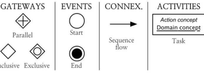
In the second layer, we represent each business function as the sequence of manipulations of business domain concepts that can carry it out. This information could be documented using several modeling techniques, e.g. UML’s Activity Dia-gram or Business Process Model and Notation (BPMN). We chose BPMN because it is easier to understand for people not working in software engineering. This is important since the building of this level of system’s description will heavily involve people from the business domain. In our models, we have limited the set of BPMN elements to those in Figure 1.
Action concept
Domain concept
Figure 1: The subset of BPMN components used in the second layer
2.2.1
Manipulations
We define a manipulation as the representation of an el-ementary processing of a business level concept, in other words a task in BPMN since they are the basic work units of the model notation. A model for the manipulations was introduced in [2] that we have reused without much mod-ification. Manipulations are thought of as simple natural language declarative sentences like “The system computes the taxes”. In that sentence, the business level information being manipulated is the “taxes” and the action is “com-putes”. Since we can ignore the subject in such sentences (because the subject is the system), manipulations are for-malized as pairs of concepts: an action concept,Computeand a domain conceptTaxes.
This representation of the manipulations into pairs of con-cepts allows us to specify a criterion for non-atomicity: a manipulation is non-atomic if we can further decompose it into a process-like sequence of manipulations (using BPMN) based on the same vocabulary of actions and domain con-cepts. Thus, the atomicity of the manipulations is tightly related to the granularity of the action and domain concep-tualizations. It is worth mentioning that the constituent parts (action and domain concept) are not described in the same layer since they could not, independently, be used to answer what does some piece of source code.
Action Concepts. The conceptualization of actions that we use to build the manipulations is represented through an ontology. At the root level we find two concepts: In-formationDeliveryandInformationHandling, which represent the most general actions we believe can be performed on business level information, either communicate it or handle it. We limited the specialization of information communi-cation to Receive and Send. The handling of information is specialized following the Model View Controller (MVC) pattern: ManipulationForControl: decision making actions based on information, ManipulationForView: actions on in-formation with visible outcome for the user and Manipu-lationForModel: actions that process the information itself. The useful specializations ofManipulationForControlare lim-ited to ValidateInput: check that the data entered by the user is valid. ManipulationForModelis slightly more complex and represents the CRUD operations (Create, Read, Up-date and Delete). ConceptManipulationForViewis first spe-cialized intoConfigureandRenderView. Configureis the ac-tion of configuring any view of domain informaac-tion whereas RenderView is the action of rendering that view. The sub-sumption hierarchy underManipulationForModeland Manip-ulationForView extends beyond the above-mentioned first level of concepts; however the full presentation of these con-cepts hierarchies would go beyond the scope the paper.
Domain Concepts. The action concept hierarchy whose idea we first introduced in [2] is specific to our work and can be considered a general contribution of our project, since it is independent both from the program under analysis and from the domain concepts. On the other hand, the modeling of a domain concept hierarchy depends on the application domain considered. It will then be described as part of the practical application of our approach in section 4.2.1.
2.3
Third Layer
The third layer of our program comprehension model de-scribes how the source code carries out the manipulations i.e. how the action and domain concept could be expressed
in the code. In the description of the layers in section 1.1 we focused mostly on the action part of manipulations. Actions are represented in the third layer elements by a set of generic programming constructs like loops, conditional statements or assignments. For example, aSearchaction could be car-ried out by the following sequence of constructs: a loop and a conditional statement. The domain concept part of ma-nipulations are represented by identifiers in the source code of programs. Indeed, software engineers use combinations of natural language words to refer to the information han-dled by their program: variables, functions and class names. It is very unlikely that developers would willingly obfuscate their source code because it would then become very hard or impossible to work with [13]. Not only has this been agreed on [9], it has also been leveraged to extract domain knowledge from the source code [14].
In short, the third layer elements are of two kinds: ab-stract program constructs and generic identifiers, they “in-stantiate” the action and domain concepts of each manipu-lation. These layer elements are abstractions of the actual programming language constructs that we would find in a specific program to analyze. They are in fact translated into actual source code (using a specific programming language constructs) during implementation.
3.
MAPPING
Because the source code is an implementation of the ele-ments of the third layer, an explicit mapping can be made between them. Moreover, the elements in any layer of our program comprehension model can be linked to the ele-ment, from the immediately upper layer, that they describe. Hence, we are able to link the source code to the business level function of the program (the first layer), in other words, we can answer the why question of some source code section. Then, we have closed the gap between the source code and the purpose of the program, which is indeed one of the ways to understand a program [4].
3.1
Mapping Model
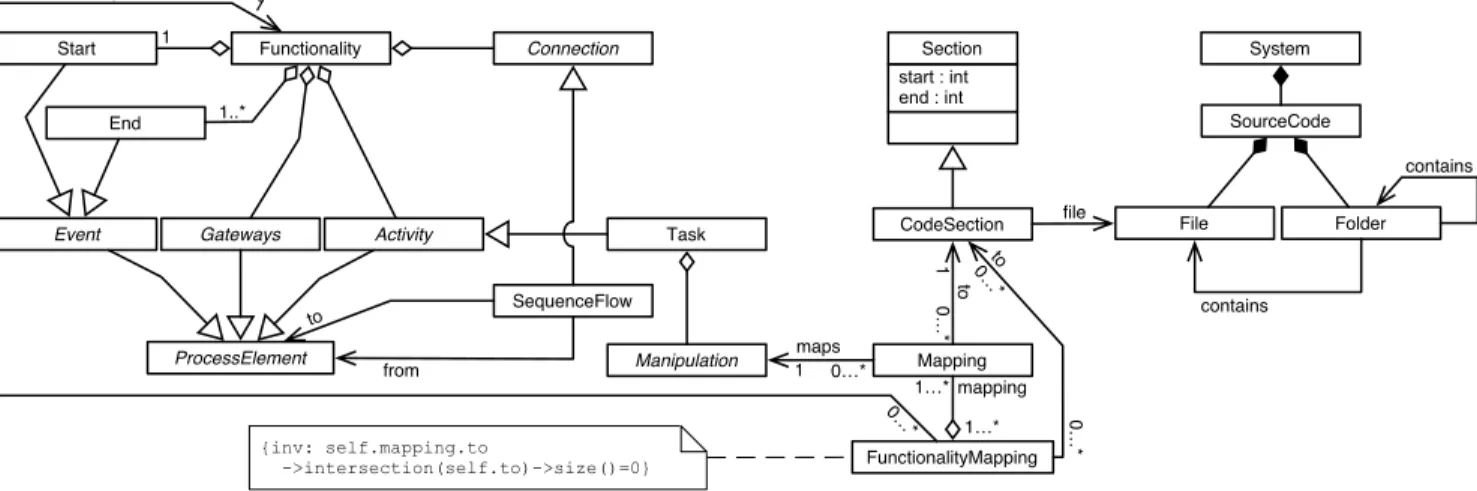
The source code directly answers the how question as well. It follows then that very little could be learned in terms of programming comprehension by exploring a mapping be-tween the source code and the elements composing our third layer model. Thus, the mappings we are interested in work-ing with link manipulations (the second layer) to the source code implementing them. Figure 2 presents the model we developed to guide the development of the tool described in section 4.1. In our model, the source code is represented by a collection of text files to stay as general as possible. With a similar purpose, each syntactically relevant code element is characterized as a contiguous section of source code iden-tified by the character numbers at which the section starts and ends.
Mapping instances link a Manipulation and a CodeSection. This means that for every mapped code section, we know the manipulation of information it is supposed to imple-ment. Since the same manipulation could be involved in several system functions, the mere mapping from manipu-lation to source code is not enough. We must also record the set of code sections belonging to some system’s func-tion: FunctionalityMapping. The function mappings can then act as a filter when exploring the mappings. Software engineers using our system interact only with the mappings
System SourceCode File Folder contains contains start : int end : int Section CodeSection file Functionality Gateways Event Task Start End 1 1..* Manipulation Connection Activity ProcessElement SequenceFlow from to FunctionalityMapping Mapping to maps maps to {inv: self.mapping.to ->intersection(self.to)->size()=0} mapping 1 0…* 1 0…* 1…* 1…* 0…* 1 0 …* 0 …*
Figure 2: Model of the mappings
relevant to the system’s function (functionality) they intend to maintain.
3.2
Automation
The third layer’s program constructs and generic identi-fiers linked to some manipulation could be used to heuristi-cally search for occurrences of the manipulation in the source code:
1. The program constructs representing the action part of the manipulation can be translated into syntax clues specific to the programming language.
2. The generic identifiers representing the concept part of the manipulation can be compared to the actual identifiers found in the source code.
The hypothesis behind this heuristic is that the presence of program identifiers matching the concept “within” the code representing the action is a sign of the presence of the manipulation in this code. A methodology is being devel-oped that leverages this technique to locate, in the code, the manipulations involved in some business function, hence to automate the production of the mappings. This is part of future work.
4.
EXPERIMENTATION
The goal of this experimentation is to validate our ap-proach through the demonstration of the usefulness of a system’s maintenance tool based on our mapping model (see section 3). The usefulness will be tested by showing that, using our tool, a developer would reduce the time necessary to provide a correct answer to a maintenance task requiring some understanding of the program to maintain. As prereq-uisite, we verified that the users in our experiment were in-deed able to use the information in the mapping provided by our tool. Hence we first ran a small experiment to perform this verification. Next, we ran the main experiment, assign-ing the developers some non-trivial maintenance tasks that would normally require the understanding of the program to complete properly. The system we used in our experiments is a large knowledge portal developed at IIT Kanpur, called Agropedia1.
1
http://agropedia.iitk.ac.in
4.1
The Tool
The tool we developped allows users to navigate mappings based on our model. It was developed as a set of Eclipse2 plugins with which it is possible to create, modify and nav-igate the mappings. The manual edition of the mappings is required since the approach is not fully automated yet.
4.1.1
Ontology representation and use
The design of a manipulation proceeds by manually select-ing both of its composselect-ing parts. In our tool we display two tree-views, one for each of the two ontologies, from which the action and domain concepts are selected. The tree-views comply with the subsumption hierarchy of the ontologies, such as that of the action ontology. Only one ontology is displayed at a time to keep the interface simple. However, the selection made in the hidden tree-view remains visible in the description of the selected manipulation (Figure 3).
Figure 3: Selecting the component concepts of a ma-nipulation
2
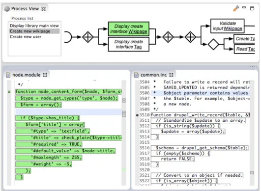
Figure 4: Source code mapped to the selected manipulation and function
4.1.2
Function Visualizer
On the top level of our model we represent the system’s functions. In our tool they are represented as a simple list of function names in which the user will select the one to display. Each such function is represented as sequence of manipulations using simplified version of BPMN (see sub-section 2.2). Then, the selected function is visualized as a graph using this very notation in the function visualizer.
4.1.3
Source Code Highlighting
The main purpose of the function visualizer is to allow the user to select the corresponding manipulation to locate in the code. Once a selection is made, the code sections mapped to the selected elements are highlighted in the in-terface. As explained in section 3.1 there are two mappings from the model to the code. First we map the code that implements some selected manipulation. This is identified with a green (grey) background. Second, we map the code that implements a system’s function. This is identified with a grey outline. Of course, when selecting a manipulation to display, the corresponding code will be highlighted both with a grey outline and a green (grey) background since it belongs both to the manipulation and to the function. But other sections of the code will only be outlined in grey since they may belong to the function but not to the manipu-lation. This can be seen in Figure 4: the outlined code in common.inc is involved in the selected function but not in the currently selected manipulation. On the contrary the code with a green (grey) background in node.module is mapped to both the selected manipulation and the function.
4.2
Study Case
Agropedia is a social knowledge repository website. It is enriched with a delivery network allowing the information to be dispatched to the farmers through the mobile network,
when no Internet connection is available. The system has been developed using several modules added on top of Dru-pal3, a PHP based open source Content Management Sys-tem (CMS). Although most of the modules used in Agrope-dia are open source, some components have been developed by the Agropedia team of developers; such is the case of the Agrotagger module which analyzes all the documents stored in the knowledge base to automatically assign them key-words. The latter are chosen from Agrovoc, an agriculture vocabulary managed by the Food and Agriculture Organi-zation of the United Nations (FAO).
4.2.1
Business Domain
Besides the Action Ontology, the representation of the manipulations requires the building of an ontology of appli-cation domain concepts (see section 2.2.1). Although the knowledge stored in Agropedia’s database belongs to the agriculture domain, the domain of the system itself (Agro-pedia) is that of the online communities. This is therefore the domain to model. Rather than starting from scratch, we were able to find a pre-defined ontology about online communities. In the paragraph below, we will describe the extensions we made to this ontology.
SIOC Ontology. The SIOC Initiative4’s ontology
repre-sents the concept model for Semantically-Interlinked Online Communities (SIOC). This includes several concepts related to CMS-based systems like Agropedia. The SIOC initiative offers a core ontology and three complementary extension modules: access, services and types. We focused on the access module, which includes the concepts related to au-thentication and authorization, e.g. roles, user-groups and permissions. The two other modules were not relevant to
3http://drupal.org 4
Agropedia. The reuse of ontologies being an important as-pect in the development of ontologies, the construction of the Agropedia ontology (our business domain ontology) was a two-step process:
1. We first produced a conceptualization of online social repositories that we called the Social Ecosystem On-tology.
2. We then extended the Social Ecosystem Ontology to produce the Agropedia ontology.
We split the process in two steps to be able to contribute to the ontology community by sharing the Social Ecosystem Ontology (the result of the first step). Indeed, the final ontology is too specific to be widely sharable. Among the concepts in the core SIOC ontology and its access module, the following were reused in our work:
• Container: since the tool is a knowledge repository, this is the concept representing the different kinds of repositories. The available specializations ofContainer areForumandThread.
• Item: something that can be placed in a container. The existing specialization of Item isPost, a message that can be placed in aForumor aThread.
• OnlineAccount: a user account in an online community site.
Social Ecosystem Ontology. The most important ex-tensions to the core ontology to model our domain were made underItemandContainer. The following are the new kinds ofItem:
• File
– Kinds of files: ImageFile,TextFile,AudioFileand VideoFile.
• Postthis already exists in SIOC but we added the fol-lowing specializations :
– WikiPagewhich is aPostthat can be modified by multiple authors.
– Commentwhich is a, usually short, response to an-otherPost.
Consequently, new kinds of Containerwere added as well: • Wiki: a container forWikiPage
• Blog: another container forPost, conceptually different fromForumandThread.
• FileContainer: a container forFile
Besides the concepts related to the managed content, we added some concepts at the root level (Thing)5:
• Device: the device used to access to the knowledge repository.
• ComunicationChannel: the medium through which the information is transmitted to a device.
• Tag: tags or labels associated to content pieces, which is common in web-based information repositories. Agropedia Domain Ontology. AllPost in Agropedia can be rated. Although rating systems are present in multi-ple content repositories we did not consider it to be general enough to be conceptualized in the Social Ecosystem Ontol-ogy. We added only one new root concept in our final ex-tension of the SIOC ontology to represent ratings ofPostby users:UserRating. The contents in Agropedia can be tagged not only by the Agrotagger (see section 4.2) but also by the users with terms represented in knowledge models. Then, we had to represent the conceptualization of the latter in the
5
Deviceand ComunicationChannelhave been further special-ized into other concepts but they were not directly involved in the analysis presented in this paper.
ontology. We considered knowledge models as containers for agricultural domain concepts and relationships. Moreover, taxonomies also exist in Agropedia and are represented as a special kind of knowledge models. Then our extensions to the ontology are as follows:
• UnderItemwe addedDomainKnowledgeElement, which is specialized intoDomainConceptandDomainRelationship. • UnderContainerwe addedDomainKnowledgeModel, a
con-tainer forDomainKnowledgeElement.
– DomainKnowledgeModelis specialized byTaxonomy: a knowledge model containing onlyDomainConcept. The next extension concerns vocabulary words. Although a vocabulary word refers to a concept it is not itself the concept. It is a mere string of characters. Hence:
• Under Item we added VocabularyWord, specialized by VocabularyTag a kind of word that is used as a tag. Then,VocabularyTagis also specialization of Tag. • UnderContainerwe addedVocabularystrictly
contain-ing sets of VocabularyWord.
The other extensions concern new types of containers that are specific to Agropedia. Each one of them has a special kind of Post it can contain. Here are a couple of examples of these new concepts:
• CropCalendar, containsCropCalendarPost. This is used to post an unformatted textual description of the dif-ferent stages of the crops relevant to the month. • DoAndDontContainer, containsDoAndDontPost. This
con-veys some very precise information about a particular crop.
4.3
System’s Functions
In our experiments we focused on three system’s func-tions, part of the first abstraction layer of our model: “Dis-play the Library Interface”, “Create a New User”, “Create a Wikipage”. All of these functions can be carried out by any user of the system.
4.3.1
Display the Library Interface
The library contains all the documents and other materi-als available. The display format consists of a graphic and a table listing the library contents. The function documented is the display of the library interface. Figure 5 shows the decomposition of the function into manipulations.
4.3.2
Create a New User
The creation of a new user starts by showing a form to the user. The user input is received from the interface and is validated before actually creating the user. The funcion, as modeled in Figure 6, ends after the sending of a notification to the new user.
4.3.3
Create a Wikipage
Similar to the user creation, the wiki-page creation func-tion starts by presenting a form to be filled and validated. A possibility offered by this interface is to create new tags simultaneously to the creation of a wiki-page. These tags will then be attached to the new post. Figure 7 describes the function as the simultaneous display of the two creation interfaces, followed both by a validation and creation of the wiki-page and by the creation of a tag or by the access to an existing tag.
Figure 5: “Display the Library Interface” function description
Figure 6: “Create a New User” function description
4.4
First experiment
The test subjects in the first experiment were four stu-dents of the Computer Science and Engineeering Depart-ment (CSE) of IIT Kanpur who had no previous experience with Agropedia. To reduce the effort that would have been required for us to teach the users the features of our tool, we designed the maintenance tasks so that they would discover these features by themselves and learn by doing. This was particularly important since not only the plugins used by our tool were new to the students but the Eclipse IDE as well. Nevertheless, a few minutes were invested before each individual experiment to introduce the different parts of our tool’s interface and some useful basic features offered by the environment.
4.4.1
Tasks
Here are the basic maintenance tasks we asked the stu-dents to perform:
1. Capitalize the project’s name in the Library view. 2. Fix a string label in the User Creation view.
3. Restrict the email addresses accepted during user cre-ation to a particular domain.
4. Raise the minimum word policy on new wiki-pages. The first task involves using the function visualizer to find the <DisplayAsGraph, Library> manipulation. Before they started with the second task, we reminded the stu-dents that our tool allowed the mappings to be visible (high-lighted in the source code view). However, because of the nature of the task, a global search is also enough to locate the code that needs to be changed. Not having used the manipulation, some students forgot to change the manipu-lation for the following task. Realizing about their mistake helped them learn the working of our tool. In the third task, the selection of the correct manipulation was neces-sary since there was no indication of any words that could be searched in the code directly. The fourth task didn’t require the students to do anything new. We remarked how-ever that, because the code was particularly obscure, the students started paying more attention to the comments of the code.
4.4.2
Evaluation
Because the manual mapping of the manipulations took us two whole days to perform, we were surprised that all the students were able to complete the experiment in less than the allowed 45 minutes (15 minutes per task). This was even more astonishing given the fact that only one of them had more than little experience with PHP or Drupal. After the experiment we asked the students two questions. They all
answered in the same way:
1. How much knowledge of the PHP syntax do you think was required to complete the tasks?
Answer: Almost no knowledge of PHP was necessary. 2. How important was it to have understood the working
of the program to solve the tasks?
Answer: No particular effort was made to try to under-stand the program, following the mappings was enough to understand the code at a syntactic level.
The key result of this first experiment is the answer to the second question. The fact that the students felt they did not need to do any effort to understand the program seem to confirm our hypothesis: the navigation through the mappings is simple enough to allow a seamless transfer of in-formation from the tool to the students. This also confirms our model to be a good program comprehension artifact al-lowing the users to perform some maintenance tasks that would, without the tool, require a good understanding of the program.
4.5
Second experiment
The second experiment assessed the usefulness of the tool for some non trivial program maintenance. A single null hypothesis was made:
H0: The understanding of a program that is
ac-quired through our tool is not useful during main-tenance tasks.
4.5.1
Variables
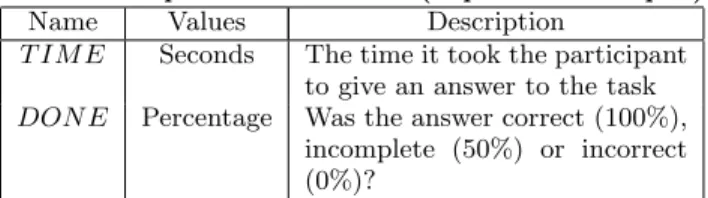
Since we know from the first experiment that the knowl-edge stored in our tool can help the users with the under-standing of a program, the second experiment must reveal if this knowledge is useful to perform some non trivial main-tenance task. This will be measured through the success of the participants in a couple maintenance tasks. The latter will be performed with and without the use of the tool. Two dependent variables are created for each task, one measur-ing the time each participant took to give an answer to the task and the second representing our evaluation of his/her answer. They are listed in Table 1.
The students in the experiment are managed by the con-trol variable: GROU P , whose possible values are “A” and “B”. All participants were asked to answer all tasks, how-ever, participants with GROU P = A used the tool for one half of the tasks while participants with GROU P = B used the tool for the other half of the tasks. The generalization of the results to a larger population of software engineers is possible if we analyze the dependent variables in relation to the independent variables in Table 2.
Figure 7: “Create a Wikipage” function description
Table 1: Dependent variables (experiment output)
Name Values Description
T IM E Seconds The time it took the participant to give an answer to the task DON E Percentage Was the answer correct (100%),
incomplete (50%) or incorrect (0%)?
Table 2: Independent variables (experiment input)
Name Values Description
P HP Ordinal The experience in PHP develop-ment, measured on a four-level ordi-nal scale: “None”(0), “Very little”(1), “Average”(2) and “Expert”(3). IDE Ordinal The frequency of use of the Eclipse
IDE, measured on a four-level ordinal scale: “Never”(0), “Once”(1), “Multi-ple times”(2) and “Regularly”(3).
4.5.2
Automation
To reduce the bias created by the presence of an experi-menter, we documented the experiment using a small web-site that we presented to the students before the experiment. Besides giving them the instructions about the tasks to per-form, the website documented the views and basic features of the Eclipse environment as well as the new views and features specific to our tool.
4.5.3
Tasks
The tasks to be performed by the participants of this sec-ond experiment are based on the same functions as in the first experiment (see section 4.3). They are categorized in three groups:
1. Tasks about the “Display the Library Interface” func-tion
• Task 1: Which line(s) of code should be changed if we wish to capitalize the first letter of the name of the project that appears in the header of the graphic in the main Library page?
2. Tasks about the “Create a New User” function • Task 2a: Which line(s) of code should be changed
so that only the email addresses from the “iitk.ac.in” domain are accepted to create a new user? • Task 2b: For the purposes of migrating the
sys-tem to a new version of Drupal, what module(s) is/are used to send new users an email with their passwords?
3. Tasks about the “Create a Wikipage” function • Task 3a: Where should a change be made to
raise the minimum number of words to 10? • Task 3b: For the purposes of migrating the
sys-Table 3: Experiment results
Par. GROU P P HP IDE w/Tool wo/Tool
1 A 3 1 2 1 2 A 2 2 2 1 3 A 2 0 2 0 4 A 1 2 2 0.5 5 B 2 3 2 0 6 B 1 1 2 0 7 B 1 0 2 0.5 8 B 1 1 2 0
tem to a new version of Drupal, what module(s) is/are responsible for managing the tags attached to Wikipages?
Task 1 being relatively easy, we used it only to famil-iarize all the participants with the tool and the mappings, it was left out during the analysis. The availability of the tool for the other tasks is controlled by the GROU P vari-able. Participants with GROU P = A answered tasks 1, 2a and 2b with the tool and tasks 3a and 3b without the tool. Participants with GROU P = B answered tasks 2a and 2b without the tool and tasks 1, 3a and 3b with the tool. Ques-tions were presented to the users in that order and the time allowed for each task was half an hour.
4.5.4
Evaluation
We evaluate the usefulness of our tool for the maintenance tasks in relation to the number of correct answers given in the allowed time. The variable DON E is used to compute the correctness of the answers given in each group. If a stu-dent succeeds in some maintenance task, DON E =1 for the task, 0 otherwise. The value displayed in Table 3 under “w/ Tool” (with tool) and “wo/Tool” (without tool) is the sum, per participant (Par.), of the DON E value of the questions in each group.
Let’s assume the variables x and y follow a normal distri-bution and represent “w/Tool” and “wo/Tool”, respectively. Since both x and y correspond to the same participant, a paired t-test can be used to reject H0. To apply this test,
our null hypothesis becomes:
H0: µd= 0, where di= xi− yi, i = 1 . . . 8
The alternative hypothesis is that the users with the tool perform better (H1: µd> 0). Therefore H0 can be rejected
if |t0| > 2.365 (statistical significance at 5%) [18], where
t0= ¯ d
Sd/√n, Sdbeing d’s standard deviation. As a result:
H0is rejected given that the estimated t0is 10.3705
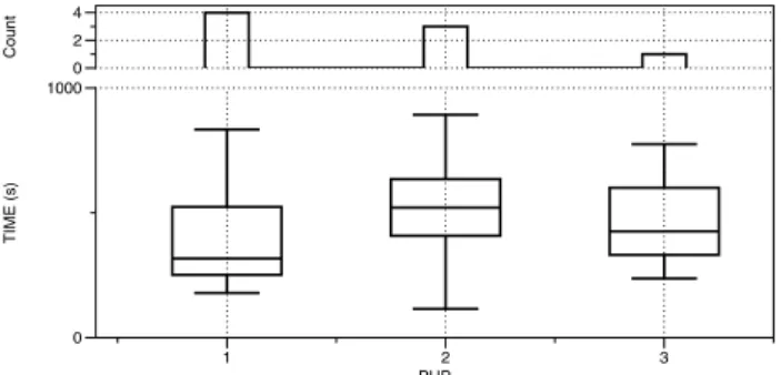
Generalization. Although we were not able to com-pletely control the P HP and IDE variables, we believe their distribution allows us to make a fair generalization. Figure 8 and Figure 9 show a couple of graphics about the time it took
T IME (s) 0 1000 Count 0 2 4 PHP 1 2 3
Figure 8: Analysis of the distribution of the P HP control variable. T IME (s) 0 1000 Count 0 2 PHP 0 1 2 3
Figure 9: Analysis of the distribution of the IDE control variable.
for the participants to give a correct answer in relation to the two control variables. The upper sub-graphic in each figure shows the number of participants for each control-variable value. For example, 3 participants are reported as having an “Average” (P HP = 2) experience with the programming language. The lower graphic shows a box plot of the time the users in each group spent to give a correct answer. In both cases we observe that similar amounts of time were spent by participants in each category. There also seems to be no relation between the time spent and the reported experience with the language or the environment: P HP = 3 partici-pants were faster than P HP = 2 but slower than P HP = 1, IDE = 2 participants were slower than both IDE = 1 and IDE = 3.
We conclude that the rejection of H0 is likely to be
gen-eralizable to software programmers with different levels of experience with the programming language and the devel-opment environment.
5.
RELATED WORK
Our approach bears some similarity to that of Gold [8] who designed a system (HB-CA) to solve the concept assignment problem. His system uses a knowledge base of programming concepts that play the same role as the business domain model in our work. His technique resembles ours since the programming notions used in his system, such as: “read file”, “write file” or “compute value” are close to our concept of manipulation. Gold’s programming notion actions seem to be the first reference to the use of actions in the concept assignment problem. However, our approach is much more sophisticated since our atomic manipulations are grounded
in a 3 levels of abstraction model and are built from two hierarchies of concepts forming each an independent ontol-ogy. In particular, the verb list used by Gold remains very basic and cannot be readily applied to other domains. Very recently, actions have been modeled as ontological concepts in robotics. Kobayashi et al. [11] did use the actions ref-erenced in the Japanese version of Wikipedia as the set of possible actions that a robot can perform. But the set of atomic actions in the resulting ontology is extremely ba-sic. Indeed all but one of the atomic actions are distributed in a single level. The authors also propose to compound actions into static sequences of actions. These sequences might remind us of our second layer describing the manipu-lation in BPMN, but are much simpler. Using ontologies in a similar manner, Parisi et al. [12] dealt with the problem of “animating” a 3D robot model using a script in natural language. To automate the process, the authors proposed to parse the scripts using the Standford Parser. Nouns, verbs and adjectives would then be matched to concepts from the “ResearchCyc” ontology (an upper ontology). Their work was not completed in the prototype. A test case was only proposed as future work. The interest in the use of ontolo-gies in software engineering is relatively new. Djuric and Devedzic [7] first explain that the Semantic Web may have absorbed all the resources in the area of ontology languages and tools. So, very few people focus on the use of ontologies in programming or software engineering. However, in their article the authors describe a new meta-DSL programming language based on ALL(D) called “Magic Potion”. One ad-vantage of this language is the possibility of using a reasoner to answer logical queries on the semantic information repre-sented in a program. It is worth mentioning that our tool could take advantage of this possibility as well since ontolo-gies enable reasoning about concepts. However, it should be tested whether the use of query languages could represent a barrier to the smooth transfer of information from our tool to the user. The management of traceability links can also be seen as a possible result of our approach. Traceability links do map requirements to source code. Since require-ments are expressed as high-level program’s function, our tool does record traceability links. It is known that the number of traceability links grows exponentially with the size and complexity of a system [5]. Tools are therefore re-quired to manage them. However, Kannenberg et Saiedian noticed in [10] that manual methods are still preferred in industry, probably because the tools available are not fully automated and still need manual intervention, which notice-ably reduces the reliability of the traceability links.
6.
CONCLUSION
In this paper we propose a rigorous source code compre-hension model built as a hierarchy of three abstraction lev-els that link the source code elements to the purpose of the program. This model leverages the notion of action ontol-ogy that we first introduced in [2]. Indeed we showed how the high level business-related function of a program can be decomposed as sequences of manipulations represented as BPMN diagrams. The model allowed us to design a tool under Eclipse to help with the maintenance of programs. To validate our approach we designed two experiments to check if code maintenance was indeed easier with the help of the tool. The results of the experiment were very encouraging since they showed that the users of the tool overperformed
the non users to a large extent. In particular the tool has proven to be easy to learn and use, and it did improve the performance of the software engineers in non trivial source code maintenance tasks of a large system (see section 4.5.4). Our approach is opened to the automation of the creation of the mappings from the source code to the manipulations. This represents our next research goal since, despite its use-fulness, the manual mapping of the source code is very labo-rious to produce. The automation would also make our tool very interesting in the context of traceability management. Indeed the traceability links could be recomputed anytime to reflect the changes in the source code (a very time expen-sive and error prone task to perform by hand).
7.
REFERENCES
[1] A. Arsanjani, S. Ghosh, A. Allam, T. Abdollah, S. Ganapathy, and K. Holley. SOMA: A method for developing service-oriented solutions. IBM Systems Journal, 47(3):377–396, 2008.
[2] J. Belmonte and P. Dugerdil. Using domain ontologies in a dynamic analysis for program comprehension. In 2nd International Workshop on Ontology-Driven Software Engineering, Oct. 2010.
[3] T. J. Biggerstaff and B. Mitbander. Program understanding and the concept assignment problem. Communications of the ACM, 37(5):72–82, May 1994. [4] R. Brooks. Towards a theory of the comprehension of
computer programs. International Journal of Human-Computer Studies, 18(6):543–554, June 1983. [5] J. Cleland-Huang, C. K. Chang, and M. Christensen. Event-based traceability for managing evolutionary change. IEEE Transactions on Software Engineering, 29(9):796–810, Sept. 2003.
[6] A. de La Garanderie. Comprendre et Imaginer. Les gestes mentaux et leur mise en œuvre. Centurion, Sept. 1987.
[7] D. Djuric and V. Devedzic. Incorporating the Ontology Paradigm Into Software Engineering: Enhancing Domain-Driven Programming in Clojure/Java. Systems, Man, and Cybernetics, Part C: Applications and Reviews, IEEE Transactions on, 42(1):3–14, May 2011.
[8] N. Gold. Hypothesis-Based Concept Assignment to Support Software Maintenance. PhD thesis, University of Durham, Aug. 2000.
[9] S. Haiduc and A. Marcus. On the Use of Domain Terms in Source Code. In 16th IEEE International Conference on Program Comprehension, pages 113–122, June 2008.
[10] A. Kannenberg and H. Saiedian. Why Software Requirements Traceability Remains a Challenge. CrossTalk The Journal of Defense Software Engineering, 2009.
[11] S. Kobayashi, S. Tamagawa, T. Morita, and T. Yamaguchi. Intelligent Humanoid Robot with Japanese Wikipedia Ontology and Robot Action Ontology. In 6th ACM/IEEE International Conference on Human-Robot Interaction, pages 417–424, 2011. [12] S. Parisi, J. Bauch, J. Berssenbr¨ugge, and
R. Radkowski. Ontology-driven Generation of 3D Animations for Training and Maintenance. In International Conference on Multimedia and
Ubiquitous Engineering, pages 608–614, 2007. [13] D. Ratiu. Reverse Engineering Domain Models from
Source Code. In International Workshop on Reverse Engineering Models from Software Artifacts, 2009. [14] D. Ratiu, M. Feilkas, and J. J¨urjens. Extracting
Domain Ontologies from Domain Specific APIs. In 12th European Conference on Software Maintenance and Reengineering, pages 203–212, 2008.
[15] S. Rugaber. The use of domain knowledge in program understanding. Annals of Software Engineering, 9(1-2):143–192, May 2000.
[16] B. Shneiderman. Software psychology: Human factors in computer and information systems. Jan. 1980. [17] A. von Mayrhauser and A. M. Vans. Program
comprehension during software maintenance and evolution. Computer, 28(8):44–55, Aug. 1995. [18] C. Wohlin, P. Runeson, M. H¨ost, M. C. Ohlsson,
B. Regnell, and W. Anders. Experimentation in software engineering. Springer, 2012.