HAL Id: cea-02339075
https://hal-cea.archives-ouvertes.fr/cea-02339075
Submitted on 13 Dec 2019
HAL is a multi-disciplinary open access
archive for the deposit and dissemination of sci-entific research documents, whether they are pub-lished or not. The documents may come from teaching and research institutions in France or abroad, or from public or private research centers.
L’archive ouverte pluridisciplinaire HAL, est destinée au dépôt et à la diffusion de documents scientifiques de niveau recherche, publiés ou non, émanant des établissements d’enseignement et de recherche français ou étrangers, des laboratoires publics ou privés.
ReactorsConsistent Approach for Multi-scale Modelling
K. Ivanov, M. Avramova, C. Schneidesch, A. Boulore, E. Royer
To cite this version:
K. Ivanov, M. Avramova, C. Schneidesch, A. Boulore, E. Royer. Uncertainty Analysis in Modelling for Light Water ReactorsConsistent Approach for Multi-scale Modelling. BEPU 2018, May 2018, Lucca, Italy. �cea-02339075�
Uncertainty Analysis in Modelling for Light Water Reactors Consistent Approach for Multi-scale Modelling
K. Ivanov1, Maria Avramova1, Christophe Schneidesh2, A. Boulore and Eric Royer3
1
North Carolina State University, Raleigh, NC 27695-7909, USA
2
Tractebel ENGIE, Avenue Ariane 7 - 1200, Woluwe-Saint-Lambert, Belgium
3
Commissariat à l'Energie Atomique et aux énergies renouvelables (CEA), 25 rue Leblanc, 75015 Paris, France
[email protected], [email protected], [email protected], [email protected], [email protected]
ABSTRACT
Compared to previous benchmarks and international activities, the Uncertainty Analysis in Modeling (UAM) is the most comprehensive initiative regarding uncertainty analysis in nuclear engineering. Light Water Reactor (LWR)-UAM is organized in three main Phases (I to III), with three exercises for each phase, and several test cases for each exercise. This approach let the participants focus on their own situation target, as VVER Steam Line Break or Boiling Water Reactor (BWR) stability analysis for instance. The test cases are based on real plant data for the three main types of LWR (i.e. BWR, Pressurized Water Reactor (PWR) and VVER) and relevant experimental conditions for validation.
UAM Phase I, devoted to multi-scale static neutronics, is almost completed. This first Phase already provides recommendations regarding sensitivity and uncertainty analysis methods, and results to be used in the next Phases, when considering time effects (depletion and kinetics) and feedbacks (fuel and moderator). The paper focuses on the link between UAM Phase II to Phase III i.e. on the link between uncertainty propagation in single physics on local scale and multi-physics uncertainty propagation on the core scale. Particularly we present the consistency in uncertainty assessment between higher-fidelity models implemented in fuel performance codes (in Exercise II-1, dedicated to fuel physics in steady state and transient conditions), and the rather simplified models implemented in thermal-hydraulics codes, to be used for coupling with neutronics in Phase III. Similarly, the uncertainty quantification on thermal-hydraulic models is established on a relatively small scale, i.e. rod bundles, in Exercise II-3, while these results will be used in Phase III at the core scale, sometimes with different codes or models (e.g. one-fluid versus two-fluid).
1. INTRODUCTION
Design and safety studies are now based on best-estimate approaches rather than conservative ones. Hence, multi-physics computation has been developed for about two decades in order to improve the confidence and the quality of numerical simulation of nuclear reactors. In addition to best-estimate methods, Sensitivity and Uncertainty Analysis (SA/UA) are necessary for validation first, and then for industrial applications. To answer this need, several exercises have been included in OECD/NEA benchmarks such as the Full Size Fine Mesh Bundle Test (BFBT)
benchmark [1]. Nevertheless, these first experiences for SA/UA were limited to single-physics. Based on this statement, the expert groups who have been involved in the previous OECD/NEA benchmarks decided in 2006 to launch the Uncertainty Analysis in Modelling (UAM) project, aimed at introducing SA/UA in coupled multi-physics calculations for Light Water Reactors (LWR-UAM). Later a similar project for Sodium Fast Reactors (SFR-UAM) has been launched. The objective of the LWR-UAM benchmark is to provide a general framework for LWR multi-scale and multi-physics computation focused on uncertainty propagation and analysis. The full chain from multi-group lattice physics up to full plant transient calculations is considered. A step-by-step approach, fully consistent, is proposed as described in Section 2. Participants can choose to propagate their own uncertainties from step to step, or to use the data provided in the benchmark specifications.
2. BENCHMARK STRUCTURE AND STATUS
The UAM benchmark covers three main topics of nuclear engineering: neutronics, thermal-hydraulics and fuel thermal and mechanical behaviour, and addresses the three main types of LWRs: Pressurized Water Reactor (PWR) (including Gen III), Boiling Water Reactor (BWR) and VVER.
2.1 Structure
As for previous benchmarks, a systematic step-by-step approach is necessary to be able to analyse the results obtained by the participants. A total of ten steps (exercises), organized in three phases, are defined:
− Phase I: stand-alone neutronics:
o Exercise I-1: cell physics. This exercise addresses the derivation of multi-group cross-sections with neutron transport codes.
o Exercise I-2: lattice physics. This exercise focuses on the derivation of few-group homogenized parameters such as cross-sections, Assembly Discontinuity Factors (ADFs), etc.
o Exercise I-3: core physics. Finally three-dimensional core calculations are considered with fixed boundary conditions for feedback parameters (e.g. fuel temperature).
− Phase II: core models without coupling:
o Exercise II-1: fuel physics. This exercise deals with fuel thermal properties relevant for steady-state and transient.
o Exercise II-2: time-dependent neutronics. This exercise addresses both fuel depletion and kinetics (fast transients).
o Exercise II-3: fuel bundle thermal-hydraulics. This exercises focuses on stand-alone fuel assembly calculations.
o Exercise III-1: core. This exercise couples neutronics and thermal-hydraulic models with fixed core boundary conditions (e.g. core inlet temperature).
o Exercise III-2: system. This exercise addresses the full plant thermal-hydraulic behaviour in steady-state and transient.
o Exercise III-3: core-system. This exercise couples the neutronics/thermal-hydraulic core and the thermal-neutronics/thermal-hydraulic system models.
o Exercise III-4: conclusion. Finally, Best Estimate Plus Uncertainty (BEPU) approach is compared to conservative calculations.
For each exercise, several test problems are considered in order to cover the different situation targets: reactor types, normal operation conditions and accidental transients.
The benchmark specifications are designed to allow a partial participation. For instance some participants may be interested in BWR situations only, or in one step only (e.g. fuel physics). For this purpose, the uncertainties to be propagated from one step to the next one are included in the specifications [2][3][4].
2.2 Status
Currently the first Phase, devoted to multi-scale static neutronics, is almost completed with many participants. The experience gained on SA/UA and on cross-section generation with uncertain parameters is directly used for next Phases, whose specifications are not yet finalized in order to include new test problems and to better ensure the consistency between exercises.
2.3 Interactions between Phase II and Phase III
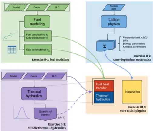
In Phase II the other physics (fuel and moderator), providing feedback in a LWR core, and time dependent phenomena are considered. Phase II is focused on uncertainty propagation in single physics models which are components of the LWR core coupled multi-physics calculations. Phase III is focused on propagation of multiple uncertainties in coupled multi-physics steady-state, cycle depletion, and transient calculations. The interactions between Phase II and Phase III are shown in Figure 1.
3. FUEL PERFORMANCE MODELLING
The Exercise II-1 is dedicated to fuel physics in steady state and transient conditions. The focus is on consistency in uncertainty assessment between fine models implemented in fuel performance codes and the rather simplified models implemented in thermal-hydraulics codes, to be used for coupling with neutronics tools in Phase III.
Classical fuel performance codes are used to model a single fuel rod, using detailed technological and operation data (geometry, enrichment, burn-up…) and high-fidelity models for fission gas release, cladding corrosion, swelling, etc. These codes will be used in Exercise II-1, while low-fidelity models, embedded in thermal-hydraulics codes, are usually preferred for full core computation in Phase III.
Discussions during the benchmark workshops rapidly underline the difficulty to consistently propagate uncertainties on fuel modelling from Phase II to III. This section presents the approach used for the LWR-UAM specifications [3][4].
Figure 1. Interactions of Phase II and Phase III of the LWR UAM benchmark 3.1 Low-fidelity models for Phase III
The so-called Doppler temperature is the main fuel physical quantity used in full core coupled thermal-hydraulic/neutronics computations. The Doppler temperature is a kind of “fuel equivalent temperature” which is used to calculate the Doppler feedback. Several methods exist to calculate it from the fuel pellet temperature distribution. A common method is to apply a weighted average between the centreline temperature and the surface temperature.
Actually the fuel temperature is calculated either for an average fuel rod at assembly (or nodal) level, or for an individual rod in a pin-by-pin (or cell-by-cell) calculation. In both cases, the fuel temperature is a result of a one-dimension heat conduction problem solution: typically, the temperature is calculated for each node of the core (3D distribution - radial and axial directions) using tabulated fuel properties, the nuclear/thermal power given by neutronics, and the local thermal-hydraulic conditions as solved by the core thermal-hydraulics model. The rod-to-coolant heat transfer coefficient is also given by thermal-hydraulics or defined by the user as input parameter.
The heat conduction problem is actually solved in two different regions: the cladding (without heat source) and the fuel pellet. The gap is modelled by a thermal resistance (or conductance), directly provided as an input data by the user, or calculated by a dedicated correlation. The fuel and cladding specific thermal properties (density, heat capacity and conductivity) are also provided, usually as functions of the temperature, and of the local burnup.
3.2 High-fidelity models for Phase III
In a typical fuel performance code, a single rod is modelled in a 1D, 2D or 3D scheme depending on the code. The boundary conditions such as coolant temperature or linear heat rate are given as input data. The axial evolution of the coolant temperature can be modelled in some cases by a simplified thermal-hydraulic module in the code. The radial distribution of power in the fuel pellet can be also often modelled by a simplified neutronics module or just fixed as input data. The fuel temperature is calculated at each axial and radial node of the meshing of the fuel rod, and the resolution of the thermal problem takes into account all the possible physical phenomena that affect the fuel geometry and thermal properties. Fuel thermal conductivity is affected by burn-up (degradation) and porosity evolution (gaseous swelling and as-fabricated porosity densification at beginning of life). Pellet deformation (thermal strain, swelling and creep) and cladding deformation (thermal strain and creep) are also considered. The gap is modelled explicitly and its thermal conductance takes into account the fission gas release from the fuel pellet. Depending on the fuel performance code, fission gas behaviour models can be quite simple (like correlations) or mechanistic (representing diffusion, gas trapping and resolution, bubble precipitation). Very often, these models are coupled to the High Burn-up Structure (HBS) formation model. In summary, in a fuel performance code, fuel temperature field, fuel rod geometry and gap conductance can be assessed. Uncertainty propagation can be performed on these quantities.
3.3 Uncertainty propagation
Due to the difference of models used in Phases II and III, the expert group has to define consistent uncertainties to be propagated. The main difficulty is to account only once in the full-core calculation for the uncertainty associated to inputs for physical quantities having an impact on the different fields of core multi-physics like fuel density for instance. The case of the geometrical uncertainties is particularly important since they affect: i) the neutronic homogenized cross-section data (through modification of the moderation ratio for instance); ii) the thermal-hydraulic channel properties (hydraulic diameter or flow area for instance); iii) the thermal and mechanical fuel behaviour. In order to avoid a double effect of the same uncertainties, only the thermal uncertain parameters are propagated from Phase II to Phase III. In practice, the two main sensible parameters are the gap conductance and the thermal conductivity. In order to cover the whole range of operating conditions encountered in a full core, with roughly fifty thousands of fuel rods, Phase II will provide response surfaces for the thermal parameters of interest in Phase III. In practice, the two main rod operating conditions to be considered as input are the burn-up and the linear power. Using SA/UA methods, Phase II will finally provide for the gap conductance and for the fuel and claddings thermal conductivities: i) the mean value as a function of the temperature, the burn-up and the linear power; ii) the standard deviation resulting from the high-fidelity model uncertainties. These data will be computed for each type of fuel rod, i.e. for each type of LWR fuel assembly of interest. As usually in LWR-UAM, each participant can derive its own uncertainties to be propagated from Phase II to III, or just use the data provided in the benchmark specifications. An example of the data generated using the ALCYONE fuel performance code [5] in steady state conditions is given on Figure 2. To summarize, the calculations performed within the framework of Exercise II-1 with the higher fidelity fuel performance code will help to develop parameterized values and associated
uncertainty bounds for these three parameters to be used in the coupled multi-physics calculations in Phase III.
Figure 2. Uncertainty on gap conductance in steady state conditions (ALCYONE code) as a function of burn-up (on left) and linear heat rate (on right).
4. CROS-SECTION MODELING
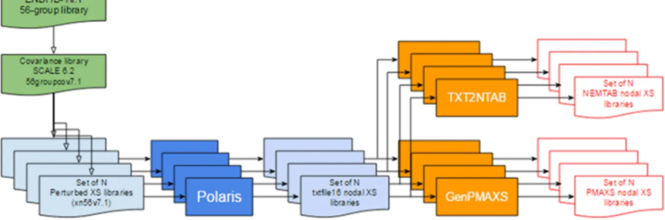
Exercise II-2 considers time-dependent neutronics phenomena – depletion (slow time phenomena) and kinetics (fast time phenomena). This exercise develops also methodologies for cross-section-modelling i.e. for generation of parameterized cross-section, kinetics and other nodal parameters uncertainty libraries to be used in multi-physics calculations in Phase III. Such methodology developed using the Sampler/Polaris sequence of SCALE 6.2.1 [6] is shown in Figure 3.
Figure 3. Process of generation of parameterized cross-section libraries plus uncertainties
5. TWO-PHASE FLOW MODELLING
As for fuel thermal and mechanical behaviour, there might have different thermal-hydraulic models used between Phases II and III. The uncertainty quantification on thermal-hydraulic
models is established on a relatively small scale, i.e. rod bundles, in Exercise II-3, while these results will be used in Phase III at the core scale. Detailed two-phase flow models, either at sub-channel level or at Computational Fluid Dynamics (CFD) level, can be used to model a single fuel bundle in exercise II-3, while rather simplified models at fuel assembly level are used for full-core thermal-hydraulics in Phase III.
5.1 Parameters of interest
Considering the feedback effect of thermal-hydraulics on core behaviour leads to identify three main parameters of interest: the coolant temperature and/or void fraction, and the cladding temperature (i.e. boundary condition for heat conduction problem in fuel rods) resulting from the heat transfer coefficient between the fuel rod and the coolant. These parameters highly depend on the flow: single-phase turbulent flow1, nucleate boiling or film boiling (post-CHF conditions). Hence Phase II should provide uncertainties on these parameters, but also on the transition criteria between the three flow regimes. As an example, one can explain the methodology for Critical Heat Flux (or boiling transition) and for void fraction.
5.2 Uncertainty on Critical Heat Flux
High-fidelity two-phase flow models are now based on multi-fluid or multi-field approaches, whose final goal is to predict the occurrence of Departure from Nucleate Boiling (DNB) or of dry-out based on local parameters such as sub-layer void fraction (case of DNB) or liquid film thickness (case of dry-out). Even if these approaches are rather new and still under development, it is necessary to assess the uncertainties on Critical Heat Flux (CHF) in Exercise II-3 even with classical correlations as they are used in core thermal-hydraulic calculations in Phase III.
As for Exercise II-1, the propagated uncertainty on CHF prediction in Phase III can be quantified with a design of numerical experiment where input uncertain parameters are varied. It is important to consider only once input uncertainties on CHF. For example, the spacer grid effect (position and mixing) on CHF and the turbulent mixing are investigated in Exercise II-1 for each type of fuel bundle (PWR, BWR or VVER). The resulting uncertainty will be considered later in Phase III in the overall uncertainty on CHF.
In addition to the propagated uncertainty on CHF prediction, several input uncertainties are considered in full-core coupled calculations with a sensible effect on CHF: the power distribution provided by neutronics, the rod displacement, the core inlet boundary conditions, either provided by the thermal-hydraulic system calculation for slow transients such as Steam Line Break (SLB), or as input data for short transients such as Rod Ejection Accident (REA). 5.3 Uncertainty on void fraction
Due to the large range of available models for two-phase flow, the benchmark specification cannot address input uncertainties to be considered for each model and all closure laws. Nevertheless the consistency between Phases II and III should be verified by the participants when different codes or models are used (four-equations model versus two-fluid model for instance). The methodology is the following: the modelling uncertainties have to be tuned in order to have the same effect on the void fraction at sub-channel level (for which it is possible to
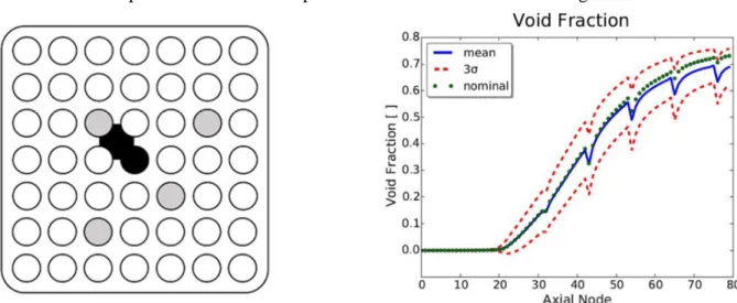
compare the computations to the measurements). As example, the obtained results of statistical uncertainty analysis perfumed with sub-channel code CTF coupled with DAKOTA [7] for BWR bundle at normal operation conditions as part of Exercise III-3 is shown in Figure 4.
Figure 4. Axial void fraction distribution for selected internal sub-channel of a BWR bundle When fine-scale models are used in exercise II-3, it is possible to compare the computations with local measurements of void fraction (512x512 pixels for instance in BFBT data), or to integrate the void fraction at sub-channel level. Then it is possible to assess the uncertainty on modelling parameters such as C0 coefficient for the drift flux model which are used later in Phase III.
6. CONCLUSIONS AND PERSPECTIVES
Using the experience gained on Phase I, a consistent approach is defined in Exercise II-2 to assess the neutronics uncertainties to be propagated from Phase II to III. Exercises II-1 and II-3 will be used to characterize the uncertainties of high-fidelity fuel and thermal-hydraulics models regarding parameters of interest at core level, such as nodal Doppler temperature or void fraction. These uncertainties are defined as functions of local operating conditions at core level (pressure, burn-up…) in order to be propagated in Phase III with rather simplified models for fuel behaviour and core thermal-hydraulics. For the three selected fuel physics quantities high-to-low fidelity model information approach is applied, and the obtained uncertainties will be propagated in the core multi-physics calculations. Phenomena Identification and Ranking Table (PIRT) analysis will be used for thermal-hydraulic quantities where common cross-cutting input have the strongest uncertainties impact for the envisioned initial steady state and transient applications It is only in those quantities that the uncertainties will be only propagated for full-core calculation. For such propagation the experience accumulated in Exercise II-3 test problems will be utilized. Finally exercises III-1 and III-3 will result in safety and design quantities such as DNB ratio with the best-estimate value and the overall uncertainty.
7. REFERENCES
[1] M. Avramova, K. Ivanov, T. Kozlowski, I. Pasichnyk, W. Zwermann, K. Velkov, E. Royer, A. Yamaji, J. Gulliford, "Multi-physics and multi-scale benchmarking and uncertainty quantification within OECD/NEA framework", Annals of Nuclear Energy, vol. 84, pages 178-196.
[2] K. Ivanov, M. Avramova, S. Kamerow, I. Kodeli, E. Sartori, E. Ivanov, O. Cabellos, "Benchmark for Uncertainty Analysis in Modelling (UAM) for design, operation and safety analysis of LWRs, Volume I: Specification and Support Data for the Neutronics Cases (Phase I)", NEA/NSC/DOC(2012).
[3] T. Blyth, N. Porter, M. Avramova, K. Ivanov, E. Royer, E. Sartori, O. Cabellos, H. Feroukhi, E. Ivanov, "Benchmark for Uncertainty Analysis in Modelling (UAM) for design, operation and safety analysis of LWRs, Volume II: Specification and Support Data for the Core Cases (Phase II)", NEA/NSC/DOC(2014).
[4] J. Hou, M. Avramova, K. Ivanov, E. Royer, M. Jessee, J. Zhang, W. Wieselquist, I. Pasichnyk, W. Zwermann, K. Velkov, "Benchmark for Uncertainty Analysis in Modelling (UAM) for design, operation and safety analysis of LWRs, Volume III: Specification and Support Data for the System Cases (Phase III)", NEA/NSC/DOC(2016).
[5] V. Marelle et al., "Validation of PLEIADES/ALCYONE 2.0 fuel performance code", Proc. WRFPM (TopFuel) 2017 Meeting, Jeju Island, Korea (Sept. 2017).
[6] K. Zeng, J. Hou, K. Ivanov, M. Jessee, “Uncertainty Analysis of Light Water Reactor Core Simulations Using Statistic Sampling Method”, M&C 2017 - International Conference on Mathematics & Computational Methods Applied to Nuclear Science & Engineering, Jeju, Korea, April 16-20, 2017, on USB (2017).
[7] N. Porter, M. Avramova, K. Ivanov, "Uncertainty and Sensitivity Analysis of COBRA-TF for the OECD LWR UAM Benchmark using DAKOTA", Proceedings: The 16th International Topical Meeting on Nuclear Reactor Thermal Hydraulics (NURETH-16), Chicago, IL, USA, August 30-September 4 (2015).