The Cosmic Ray Muon Energy Spectum via
Cerenkov Radiation
FMASSACHUSETTS INOF TECHNOLO
by
AUG 13 20
Eric Antonio
Quintero
LIBRARIE
Submitted to the Department of Physics
in partial fulfillment of the requirements for the degree of
Bachelor of Science
ARCHIVES
at the
MASSACHUSETTS INSTITUTE OF TECHNOLOGY
June 2010
@
Eric Antonio Quintero, MMX. All rights reserved.
The author hereby grants to MIT permission to reproduce and
distribute publicly paper and electronic copies of this thesis document
in whole or in part.
A uthor
...
....--....
-..
--..--.
Department of Physics
May 14, 2010
Certified by...---...
Professor Ulrich Becker
Thesis Supervisor
Accepted by ...
...
Professor David E. Pritchard
Senior Thesis Coordinator, Department of Physics
The Cosmic Ray Muon Energy Spectum via Cerenkov
Radiation
by
Eric Antonio Quintero
Submitted to the Department of Physics on May 14, 2010, in partial fulfillment of the
requirements for the degree of Bachelor of Science
Abstract
In this thesis, I designed and constructed a basic Cerenkov detector to measure the energy spectrum of cosmic ray muons for use in the graduate experimental physics courses, 8.811/2. The apparatus consists of a light-tight central volume with a pho-totube to detect the Cerenkov radiation of muons whose speed is higher than the speed of light in the medium with which the volume is filled. The measurement is triggerd by coincidence in scintillating detectors above and below the volume. I con-structed a signal chain for measurement, collected data for muon energies with the goal of constructing the muon energy spectrum from different Cerenkov spectra. In the range 20-100 GeV, the spectrum is found to obey a power law with exponent -a = -2.90 t .04, which compares well to the value of -2.844 found in the litera-ture. In addition, calculations and considerations were made to aid in the use of this apparatus in a pedagogical manner.
Acknowledgments
There are many people who this thesis owes its existence to. Foremost, I thank Professor Becker for taking me on for this project. His assistance and advice were absolutely vital to every aspect of this experiment. I thank my family for their love and support throughout my time at MIT. I thank my fellow seniors in Physics, for providing therapeutic sessions for discussing our theses and future plans.
Finally, I dedicate this thesis to Evelyn G6mez, who gives me the strength to do the impossible. I thank her for being there every day that I needed her.
Contents
1 Introduction
1.1 Background . . . . 1.2 Cosmic Ray Muons . . . .
1.3 Goals. ... .. . .. .
2 The Cerenkov Effect
2.1 Basic Theory . . . . 2.2 Photon Production . . . . 3 Experimental Setup 3.1 Construction . . . . 3.2 Signal Chain . . . . 3.3 Calibrations . . . . 3.3.1 PMT Plateau . . . 3.3.2 Gating . . . .
3.3.3 Photon Counts and 3.4 Estimations . . . .
3.5 Measurements . . . .
4 Data
4.1 Air and CO 2 Measuremer
4.2 Scintillator and Water Mea 4.3 Photon Number Spectra .
. . . . . . . . ... ... .. .... ... . . . . .-. .-. .-. .-. .-. .-. .-. .-. .-. .-. .-. .-. .-. .-. .-. .-. .-. .-. .-. .-. .-. .-. .-. .-. . . . . . . . . . . . . . . . . . . . . Light Transmission . . . . . . . . . . . . ts . . . . surem ents . . . . . . . . 13 13 14 15 17 17 18 23 23 23 25 25 26 27 29 29 31 31 32 32
5 Analysis
5.1 Preliminary Analysis . . . . 5.2 Obtaining Energy Spectra . . . .
5.2.1 Bin Scaling . . . .
5.2.2 Differential Spectrum . . . 6 Discussion
6.1 Results . . . .
6.1.1 Differential Spectrum Fit .
6.2 Future Work . . . . 6.3 Conclusions . . . . A Acceptance Ratio MATLAB code
B Reference Data C PMT Information from [8] 35 35 36 36 37 51 53
List of Figures
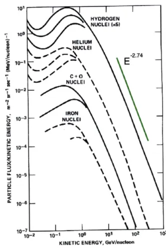
1-1 Distribution of energies of galactic cosmic rays, measured near Earth.
Below a few GeV, the Sun influences the intensities strongly, depending on levels on solar activity.
[]
. . . .1-2 Illustration of a Cosmic Ray shower. (Adaptation of CERN graphic) . 2-1 Sketch of Cerenkov radiation geometry (Diagram created by Arpad
Horvath) . . . . 3-1 3-2 3-3 3-4 4-1 4-2 4-3 4-4 4-5 5-1 5-2 5-3 5-4 5-5 5-6
Photo of Experimental Apparatus . . . . Block Diagram of signal chain. Total PMT amplification: Plateau Curves for Scintillating Detectors . . . .
Comparison of apparatus run with and without gating .
300 x
Raw Spectra without cuts . . . . Data with error bars and cuts at bin 20 . . . .
Raw Spectra without cuts . . . . Data with error bars and cuts . . . . Photoelectron Spectra, using 40 MCA bins
/
photoelectron. . . . 18 . . 24 . . 25 . . 27 . . 28 . . . . 31 . . . . 32 . . . . 33 . . . . 33 . . . . 34 Logarithmic Plots for Air and CO2 . . . . . . . .
Logarithmic Plots for the scintillator and water . . . . Relating MCA bins to Muon momentum . . . . Detail of Fig. 5-3, examining low energy behavior of air and CO2 Cerenkov M odulation . . . . Measured Differential Muon Intensities . . . .
6-1 Fit to combined measured data . . . . 44
A-1 Monte Carlo generated density of muon events in top and bottom paddle 50
B-1 Muon reference data from
[.
. . . . 51B-2 Muon reference data from [5] (Integral intensity refers to intensity of muons at or above a given momentum) . . . . 52
C-1 Data relating to the quantum efficiency. Quoting: "(b) Cathode
cur-rent as the function of the operating voltage; (c) Cathode curcur-rents of PMT 9350KA-7917 and the reference PMT D642KB-6128; (d) Cath-ode currents of PMT 7267 and the references PMT
D642KB-6128; (e) Cathode currents of PMT 9350KA-7891 and the reference
PMT D642KB-6128. The cathode currents in (c), (d), (e) are absolute values." . . . . 53
C-2 "(a) System setup for DC gain and dark current measurement; (b),
(c), (d) gain and dark current for D642KB-7267, 9350KA-6521 and D642KB-7347. The round marker line is dark current and square marker line is gain. Dark currents are absolute values." . . . . 54
List of Tables
2.1 Cerenkov threshold energies . . . . 20 2.2 Cerenkov angles . . . . 21
Chapter 1
Introduction
1.1
Background
The phenomenon of cosmic rays has been intensely studied, and is still not fully understood. The first indication that radiation from space existed on Earth was due to the meticulous work of Viktor Hess. Hess was the first to measure that the level of ambient radiation on Earth increased with altitude, and deduced that the radiation must be originating from space and interacting with the atmosphere to produce lower levels further down.[]
The most energetic particles we can measure occur in cosmic rays, and the highly penetrating muons, which result from collisions with the atmosphere, are an impor-tant source of background noise for many sensitive underground experiments. Thus, the angular dependence and energy spectrum of the particles we can detect at ground level is of interest, in order to ensure efficient operation of detector experiments.
However, for teaching laboratories, cosmic rays can be a useful source of "free particles", requiring neither apparatus or regulatory procedures that would be needed to accelerate particles to such energies manually. The practical aim of this thesis was to build and test an experiment for use in a graduate laboratory course at MIT, so cosmic rays provide a good resource for a particle physics experiment with limited materials.
14 Introduction
1.2
Cosmic Ray Muons
Cosmic rays, which are ionized nuclei, regularly impact the Earth's atmosphere at relativistic energies. Their composition is roughly 90% protons, 9% o particles and only 1% are heaver nuclei. In particular, cosmic rays with energies of up to 1020 eV have been detected, which is incredibly more energetic that the 7 x 10¹² eV protons
which are being produced in the LHC at CERN[71]. The energy spectra of some different kinds of primaries are shown in Fig. 1-1. Most cosmic rays are thought to be of galactic or even extra-galactic origin, and the mechanism for their production is unclear.
[2]
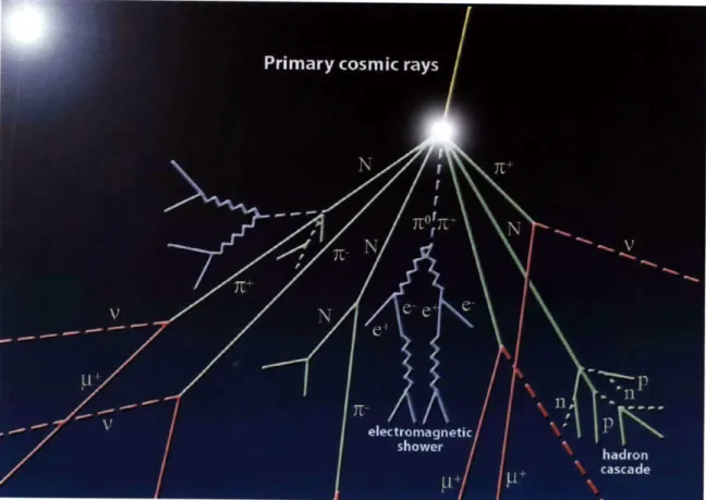
When these energetic nuclei impact the atmosphere, they soon interact with atomic nuclei there. The amount of energy released causes an atmospheric cascade of particles which travel down towards the Earth's surface. Depending on the specific energy of the cosmic ray and environment in which it collides, up to 109 particles can be produced in such a cascade, whose trajectory remains within one degree of the primary particle's path. Typical products in these reactions are the lighter charged mesons, the majority of which are 7i, and some K±. These can decay by the following pathways:
7Tr+orK+ _ + + v, (1.1)
r--orK~ -~- + i, (1.2)
Muons were discovered via cosmic rays by Bruno Rossi [6]. A very inventive ex-perimentalist, Rossi first measured the presence of muons in cosmic rays, and their unstable nature (the first such discovered particle). Muons have a much smaller inter-action cross section than pions and kaons, since they do not participate in the strong interaction, and are stable enough to make it to the Earth's surface before decaying. Thus they are very penetrating, and indeed often referred to as the "penetrating component" of cosmic rays, which results in their presence in underground detector experiments. These cosmic ray muons travel at near-light velocities, and thus when muons impact solid matter on the Earth, we may observe the Cerenkov effect.
1.3 Goals 15 g HELIUM -2 -- ANUCLEI >, E C+O\ NUCLEI \ 10-2 IRON 0-O NUCLEI S10-us cc' -71 10-2 10-1 109 101 102 103 KINETIC ENERGY, GeV/nAcleon
Figure 1-1: Distribution of energies of galactic cosmic rays, measured near Earth. Below a few GeV, the Sun influences the intensities strongly, depending on levels on solar activity. [4]
1.3
Goals
As suggested by measurements such as those in Fig. 1-1, primary cosmic rays seem to obey a power law of E-2 7 4 in their energy spectrum. We expect, since the cosmic ray muons are produced by primary particles who all approximately exhibit this power law behavior (Fig. 1-1), that the muons will show an similar functional form for their energy spectrum, even after cascaded decays.
Particles with sufficiently high energy can create radiation when traveling through a medium, rather than vacuum, by the Cerenkov effect, which will be detailed in chapter 2. It will be discussed how measuring the number of photons a particle produces in a volume serves as a measurement of its energy. With this experiment, the goal was to infer as much information about the cosmic ray muon energy spectrum
16 Introduction
Figure 1-2: Illustration of a Cosmic Ray shower. (Adaptation of CERN graphic) as possible, using the measurement of Cerenkov radiation in a volume filled with substances of various indices of refraction. Moreover, it was the goal to perform the measurement without the use of a magnetic field in the measuring apparatus. As will be discussed, this leads to limitations in determining the exact energies of the muons since we use a photomultiplier tube to measure the Cerenkov effect.
Three main media were used to investigate muon energies: air, CO2 and water. The apparatus was also run with a scintillator plate, to facilitate the setup and compare to the other measurements.
Chapter 2
The Cerenkov Effect
2.1
Basic Theory
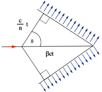
The Cerenkov effect is the existence of a certain kind of electromagnetic radiation when a particle is traveling through a medium at a superluminal velocity for that material. This can be understood through Huygens' Principle, when a wave source is traveling faster than the waves it emits. In this case, a linear shockwave forms, resulting in a front of photons propagating through the material.
Constructing the right triangle of velocities, with hypotenuse
#c
and adjacent sidec/n, we see that the angle that the photons' trajectory makes with the trajectory of
the particle is given by
1
cos(0c) (2.1)
n#
Thus, the angle at which the Cerenkov radiation is emitted is a function of the particle's velocity, and specifically, if the velocity is such that is greater than unity, no Cerenkov radiation will be emitted. By standard relativistic kinematics, we can turn the threshold velocity condition into a condition on particle energy, giving
Ethresh((n, m) =nc 2 n (2.2)
18 The Cerenkov Effect
O~ct
Figure 2-1: Sketch of Cerenkov radiation geometry (Diagram created by Arpad Hor-vath)
energy of the particle increases, so does the angle. For An = n - 1 << 1, this can be approximated by
mc 2
Ethresh(n, n) = (2.3)
v2An
The Cerenkov threshold energies for various particles in air, water and glass are shown in table 2.1. Table 2.2 shows Cerenkov angles calculated for the media that are used in this experiment. This maximum angle occurs as the velocity of the particle approaches the speed of light, i.e.
#
- 1 and cos 0c,max =2.2
Photon Production
Energy lost by a Cerenkov radiating particle of charge q in a general dispersive medium with index of refraction n(w) and permeability p(w) is given by the Frank-Tamm formula:
dE = w (1 - 2 dxdw
47r v2n2(W)
The majority of the photons emitted are in the ultraviolet range, and tail off into the visible spectrum. Taking into account that the UV photons will not transmit ... .. ... ... .
2.2 Photon Production 19
through the glass of a PMT, one can make a practical approximation[1] resulting in a relation for the number of photons produced per unit path length per unit energy interval that will be detected in a PMT:
d2N axz2 o
~~-sin C
dEdx hc (2.4)
~-1 370 sin2 Oc(E) eV- cm-1 (z = 1) [1]
This function is itself a function of E, so we see that the number of photons is not directly proportional to the energy of the original cosmic ray muon, because the Cerenkov effect modulates the signal. Furthermore, the precise modulation will be a function of the specific Cerenkov medium, since Oc is a function of the index of refraction. This must be accounted for in order to obtain a proper energy spectrum. In our practical setup, the number of emitted photoelectrons will also depend on multiple quantities, some of which are unknown:
* The length travelled through the medium. 1
" The light transmission of the setup, ql " The PMT cathode quantum efficiency, 'cath
" The light attenuation, 6(hv)
" The fraction of Cerenkov photons which are above the infrared cutoff, f(hv)
Thus, the total photoelectrons due to a muon with energy E will be
E+A E
370
f
Ney (E) = [11 T/ath6(hv)f(hil)1 1 sin
2
c(E) E dE (2.5)
cm eVf 2
If we assume that the quantities within the square brackets are slowly varying
functions of E and hv, for the purposes of functional fitting, we can use the following form:
20 The Cerenkov Effect
Ney (E) = A l sin2 Oc(E) E
(2.6)
Thus, when looking at the MCA spectrum of events, given the inverse power law form of the primary cosmic ray energy spectrum discussed in chapter 1, we expect the form:
N (E) = A' 1 sin2 Oc(E) E--- (2.7)
where ce is an unknown constant of the spectrum to be measured. If the constant
A is the same for each medium, we can find the ratio between the number of photons
produced in each medium, which depends on 1 sin2 Oc(E).
Above 20 GeV, sin2 Oc(E) is essentially equal to 0c,ax for all three media. Given
the 80cm path length in the gaseous media, and 20cm path length in water, this results in the ratio:
Nair : Nco2 : Nwater = 1 : 1.6 : 190
However, this ratio will in practice be observed, since rh is not the same for water. The effect of this difference will be observed in the measurements.
Table 2.1: Cerenkov threshold energies
Air (An = 2.9 x 10⁻⁴) CO2 (An = 4.5 x 10⁻⁴) Water (n = 1.333)
e 20.75 MeV 16.7 MeV .75 MeV
y 4.4 GeV 3.52 GeV 159 MeV
7r 5.6 GeV 4.5 GeV 204 MeV
K 20.5 GeV 16.5 GeV 746 MeV
2.2 Photon Production 21
Table 2.2: Cerenkov angles Medium 0 c,max sin 2 (Oc,max) Air 1.380 5.8 x 10⁻⁴ CO2 1.720 9.0 x 10⁻⁴ Water 41.40 .44
Chapter 3
Experimental Setup
3.1
Construction
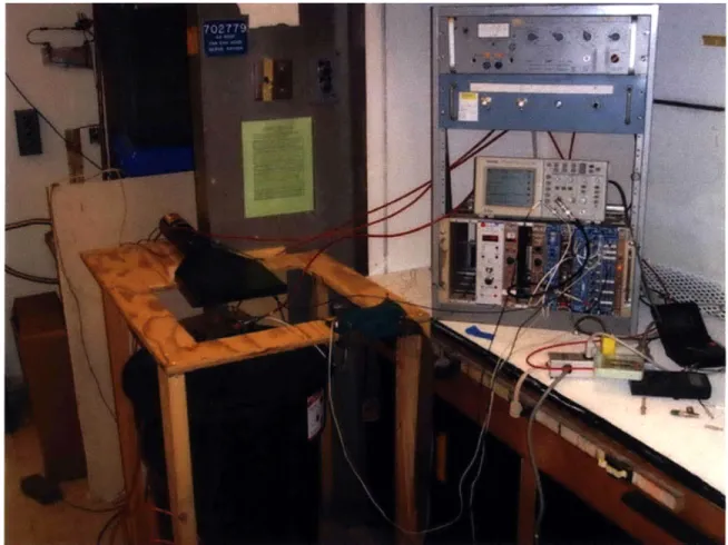
The essential construction of the experiment consists of a light-tight opaque plastic trash can, with a hole drilled in the lid to permit the insertion of a phototube. A wooden frame was designed to enclose the trash can, and provide space to place paddles of scintillator with attached phototubes above and below the volume. The horizontal cross-section of the space in which traversing particles would be detected
by both paddles was smaller than the cross section of the trash can; thus any particle
detected to pass through both paddles is guaranteed to pass through the volume. The inside of the trash can was lined with aluminum foil to increase the number of photons that would be detected by the phototube.
3.2
Signal Chain
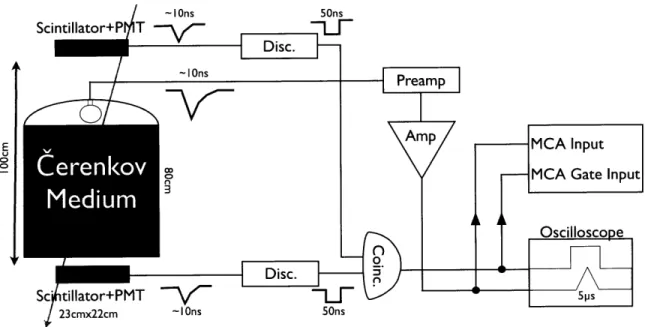
The signal chain was designed as follows: The signals from the top and bottom scintil-lation detectors were fed into -30mV discriminators and the output into a coincidence circuit. Since cosmic ray muons travel very nearly at the speed of light, the time delay between pulses from the top and bottom paddles is much less than the coincidence window of the circuit. The rate of coincident events detected was typically on the order of 0.5 Hz, whereas the number of accidental events is given by the relation
Experimental Setup
Figure 3-1: Photo of Experimental Apparatus
Nacc = 2TN1N2, where r is the time overlap for coincidence, and N1 and N2 are
the rates at which each individual detector registers events. Evaluating this results in a rate on the order of 5 x 10⁻⁴ Hz. Thus, we conclude that the signal chain as constructed effectively detects particles traversing the volume. The output of the coincidence circuit is fed into a 5 ps gate generator.
The central phototube (See Appendix C for details), inside of the trash can, was used to directly measure the Cerenkov photons that are in the visible spectrum. Its output was fed into a low noise phototube amplifier, and then to a standard amplifier, set to invert the signal to a positive pulse. The total gain on the signal was 300 x. The amplifier output was led into a portable multichannel analyzer, connected to a PC. Additionally. The MCA was gated by the gate generator triggered by the scintillator coincidence.
The signal chain was tested by laying a disc of scintillator in the bottom of the 24
3.3 Calibrations 25
E Im mput
0
--- MCA Gate Input
Oscilloscope
Disc.
Sc tillator+PMT -||ps
!23cmx22cm ~10ns 50ns
Figure 3-2: Block Diagram of signal chain. Total PMT amplification: 300 x
trash can, and coincident events in the scintillating paddles indeed corresponded to a measured signal in the central tube.
Table 3.1: Details of apparatus PMT Preamplifier Discriminator Coincidence Gate Generator Amplifier Multichannel Analyzer
used in the signal chain LeCroy 612A LeCroy 623Z LeCroy 365AL LeCroy 222 Ortec 575A AmpTek 8000A
3.3
Calibrations
3.3.1
PMT Plateau
The first calibration goal was finding a voltage to be applied to the scintillating detectors used for triggering the measurement, to maximize detection efficiency while reducing noise from thermal electrons. This voltage was found by "plateauing" the counters, in the following manner.
26 Experimental Setup
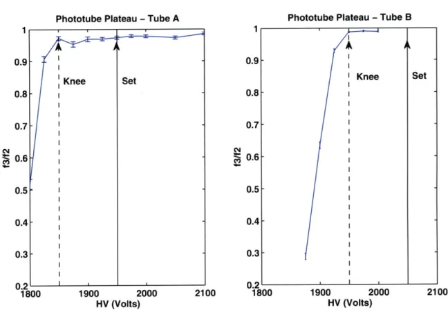
The two counters under consideration are stacked, along with a third additional counter on top, whose detecting area is smaller than the others. As cosmic ray muons encounter the counters, we concern ourselves with muons that traverse the detecting area of all three. The bottom counter and top counter are held at an fixed high voltage. The voltage of the middle counter is then varied to find the "plateau", i.e. when all triggers create a signal in the counter being calibrated.
Two signal chains are arranged, one coincidence circuit to provide counts when the top and bottom counters both register an event, f2, and one other to count the coincident events in all three,
f3.
Measurements are made as a function of the middle counter's voltage to determine L. This variation results in a "plateau" curve, since atf2~ low voltages, the middle counter will not detect all events of particles transversing the stack, while at high voltages, it should detect all events traversing the stack. Since the top counter is smaller than the others, the fraction should approach unity.The ideal operating voltage for the middle detector is then determined by estimat-ing the location of the "knee" of the plateau curve, and addestimat-ing 100 Volts, for safety. The process is then repeated as necessary. The curves obtained from this process are shown in Fig. 3-3.
3.3.2
Gating
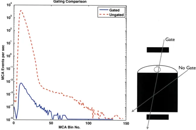
The effect of the gating was investigated in the following way. Two measurements were performed under the exact same experimental settings, but one was performed with gating disabled at the MCA. The ungated rate spectrum was found to have very many more counts in the lowest region of the spectrum, whereas at higher bin numbers, the gated and ungated spectra had no qualitatively significant difference. Still, the ungated rate will be higher all regions, as the gating mechanism is limited to a smaller solid angle. A comparison of the gated spectrum and the ungated is shown in Fig. 3-4
Hence, it was concluded that the gating mechanism was functioning correctly in eliminating unwanted noise counts and incomplete muon trajectories from the measurement.
3.3 Calibrations 27
Phototube Plateau - Tube A Phototube Plateau - Tube B
1900 2000 2100 1800 1900 2000
HV (Volts) HV (Volts)
2100
Figure 3-3: Plateau Curves for Scintillating Detectors
3.3.3
Photon Counts and Light Transmission
Later in the course of the experiment, a small LED was hung in the apparatus while empty, in an attempt to find a correspondence between MCA bin number, a reflection of the PMT signal size after amplification, and number of photoelectrons originally detected by the PMT. The direct PMT output was examined, while the voltage to the LED was varied, to determine the voltage at which the LED would emit just enough to stimulate one photoelectron. The data through the signal chain was then collected to see the MCA output. Two main peaks were observed, one peak near the zero channel corresponding to no detection, and a smaller secondary peak around bin 40 representing one photoelectron. However, because of smearing effects of the amplification chain, this is only a rough estimate. The stated result is 40 ± 20 MCA channels per photoelectron.
-28 Experimental Setup Gating Comparison 10, Gatede 10 1 N GaGate o10 0 1 oi 0 No Gate 1-21 10 2 10-3 10 50 100 150
MCA Bin No.
Figure 3-4: Comparison of apparatus run with and without gating
In general, it did not seem that the aluminum foil lining was very effective in reflecting the Cerenkov radiation. However, an additional difficulty presented itself in the case of water. Most of the Cerenkov radiation in water occurs at around the maximum angle of 41.4', given the very low energy threshold. The walls of the container are fairly near to vertical, so for a completely vertical muon (where the angular intensity is highest), the reflected Cerenkov photon's angle of incidence with the surface after reflection will be near to 41.4' degrees. The angle for total internal reflection in water is approximately 48', making rh very small for water.
Hence, the geometry was not ideal for the use of water as a Cerenkov medium, and this decreases the total number of photons detected for water by some unknown amount. This manifests itself as a large difference in the predicted photon ratio in section 2.2, and what is actually observed, which will be detailed in section 5.2.1. In future work, it may be possible to invert the PMT and submerge part of the tube in the bottom of the apparatus to improve the acceptance, by avoiding total reflection.
3.4 Estimations 29
3.4
Estimations
Given the geometry of the detector, only muons with certain trajectories will pass through both scintillating detectors and be measured by the apparatus. A Monte Carlo calculation was made to find the acceptance ratio of the setup, as well as the expected rate of muon events for various paddle separation; the MATLAB code is included in appendix A.
For im paddle separation, the simulation provides an acceptance ratio of R 0.13401, predicting a rate of approximately 100 coincident muons per minute. Ex-perimentally, the apparatus detected 30 muon gates per minute, around 20 of which were recorded in the MCA spectrum. Given the inefficiency of the light transmission within the apparatus, this is not necessarily an overwhelming discrepancy. This could be further investigated by using a gate counter external to the MCA to record the number of gates, rather than the number of recorded events above threshold. How-ever, it is important to note that the small acceptance ratio of the setup means that there are many more Cerenkov events occurring within the volume that cannot be triggered on. This is why most advanced detectors use large scintillating detectors to cover large solid angles.
3.5
Measurements
Four measurements were performed, with varying media: Air, CO2, scintillator and
water. For the CO2 measurement, it was necessary to drill a small hold near the top
of the apparatus to inlet gas from copper tubing. In addition, all of the container's seams were taped over to minimize the leak rate. A CO2 tank was then connected to inlet the gas to the approximately 4 cubic foot container at a rate of 1 cubic foot per minute. For the scintillator measurement, a circular disk of scintillator was cut to the dimensions of the bottom surface of the apparatus and laid there. Finally, for the water measurement, the container was filled to a height of 20cm. Measurements were made over the course of about 2 days, to improve the counting statistics.
Chapter 4
Data
4.1
Air and CO
2Measurements
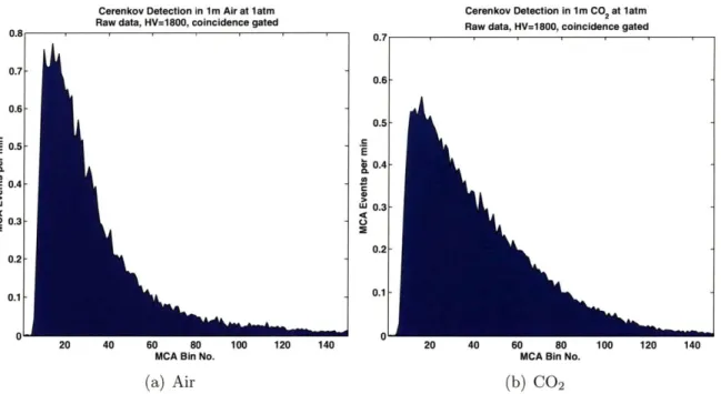
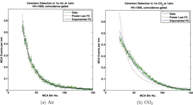
Raw spectra for Air and CO 2 are shown in Fig. 4-1. Fig. 4-2 show the data with cuts,
errorbars and preliminary functional fits. Based on examination from the gating in section 3.3.2, we define a 20 channel cut for the air and CO 2 spectra, and use these cuts throughout.
Cerenkov Detection in 1m Air at 1atm
Raw data, HV=1800, coincidence gated
20 40 60 80
MCA Bin No.
(a) Air
120 140
Cerenkov Detection in 1 m CO2 at 1atm
Raw data, HV=1800, coincidence gated
0.4
J 0.3
20 40 60 80
MCA Bin No.
(b) CO2 Figure 4-1: Raw Spectra without cuts
0.8 0.7 0.6 0.5 0.4 U 0 0.3 140
Cerenkov Detection in 1m Air at 1atm
HV=1800, coincidence gated
MCA Bin No.
(a) Air
Cerenkov Detection In 1m CO2 at 1atm
HV=1800, coincidence gated
MCA Bin No.
(b) CO2
Figure 4-2: Data with error bars and cuts at bin 20
4.2
Scintillator and Water Measurements
Raw spectra for the scintillator and watermeasurements are likewise shown in Fig.
4-3. Fig. 4-4 show the data with the noise channels cut, errorbars and preliminary
functional fits.
4.3
Photon Number Spectra
As discussed in section 3.3.3, it was possible to make a rough correspondence between
MCA bins and number of photoelectrons in the PMT. The relevant spectra are shown
in Fig. 4-5. Since the water spectrum covers a wider range of bins, each bin covers a smaller range of energies than in the gas spectra, which spreads the spectrum. Eventually, it will be shown in Fig. 5-6 that the water spectrum is brought into line with the others when this is corrected for. It was attempted to fit these curves according to the relations in section 2.2, but ultimately unsuccessfully.
Data 0.6 0.5 E i 0.4 a. IL0 U 0.3 0.2 0.1
4.3 Photon Number Spectra 33
Measurement with Scintillator Plate Raw data, HV=1800, coincidence gated
50 100 150 200 250 300 350 400
MCA Bin No.
0.14 0.12 0.1 0 C 0.08 e o006 0.04 0.02 450 500
Cerenkov Detection in 20cm Water Raw data, HV=1800, coincidence gated n-i1R.
bU 100 10 200 250 300 350 4
MCA Bin No.
(a) Scintillator (b
Figure 4-3: Raw Spectra without cuts
Measurement with Scintillator Plate Cerenkov
HV=1800, coincidence gated HV=180
50 100 150 200 250 300 350 400 450 500 MCA Bin No.
(a) Scintillator 0.4 0.35 0.3 0.25 0.2 0.15 0.1 0.05 ) Water Detection in 20cm Water 10, coincidence gated 50 100 150 200 250 300 350 400 450 500 MCA Bin No.
(b) Water
Figure 4-4: Data with error bars and cuts
450 500
10 0
-1
100 10 1
Approximate number of photoelectrons
Figure 4-5: Photoelectron Spectra, using 40 MCA bins
/
photoelectron DataApproximate Photoelectron Rates
+ Air
Co
+ 2 + Water ++ -+ + -*- +-* +ms+ ++u-1+ -HNI-+ - ~+uuelHE-iiimMM+
+-10-2 10-4 10~1 102 1149 - , - - - -.- " t -- - - -- -- I 4Chapter 5
Analysis
5.1
Preliminary Analysis
The signal height produced by the PMT and measured at the MCA is proportional to the number of photoelectrons produced by Cerenkov photons inside the medium, subject to poisson statistics and modulated as discussed in chapter 2. Thus, the MCA is measuring the frequency of events with varying pulse heights, and this range of frequencies constitutes the raw spectrum. From this data, we aim to make conversions necessary to compare to reference spectra, which can be approximated by inverse power laws over certain ranges.
By this reasoning, we examine power law and falling exponential fits to the data,
to examine their efficacy. To this end, we can examine the data in two kinds of representation: a plot logarithmic in both axes shows power law relations as straight lines and a plot which is logarithmic in y but linear in x shows exponential functions as straight lines (though allowing for a constant background introduces curvature). These plots are shown in Fig. 5-1 and Fig. 5-2.
For the air and scintillator spectra, neither type of functional fit seems superior. However, for the CO 2 and water spectra, it is very evident that the data do not re-semble a straight line in the log-log plots. We see that the data is better approximated
by exponential functions.
36 Analysis
as they cause higher numbers of Cerenkov photons to be emitted, for a given energy, as the muons pass through the apparatus. Thus, at first sight, the spectra do reflect characteristics of Cerenkov radiation.
5.2
Obtaining Energy Spectra
5.2.1
Bin Scaling
We know from chapter 2 that the Cerenkov effect modulates the amount of photons produces from linearity, so that the signal size in the PMT is not directly proportional to the original cosmic ray muon energy. Furthermore, the exact relation between the two depends critically on the medium being used in the detector. Thus, converting the MCA channel index to an energy axis is not straightforward. Without a di-rect measurement of the PMT response to different energies, this limitation must be carefully considered.
One analysis proceeded in the following manner: from the integral spectrum in the reference data [5], it was possible to find a cumulative distribution function (CDF) of sorts, i.e. at a given momentum, what fraction of the total events will occur above this momentum, by cubic spline interpolation. At these momenta, /3 is high enough that
cP ~ E, so in the following, we will be discussing momenta, for better comparison to
the reference data.
Similarly, by numerical integration of the measured spectra, a similar CDF could be constructed for the air, CO2 and water spectra. (The scintillator spectrum is excluded, because the Cerenkov effect is not responsible for its spectrum.)
Using these CDFs, a mapping can be made from momentum to MCA bins. For example, one can find from the reference that half of the measured events occur at or above some momentum P. Then, the MCA bin at or above which half of the
MCA events occur would correspond to this momentum. The situation complicates
somewhat for the gaseous media, however, since a non-negligible portion of the muon spectrum lie below the Cerenkov threshold for these media. However, the CDFs can
5.2 Obtaining Energy Spectra 37
be resealed to accommodate this effect.
The relation between momenta and bin numbers for the three Cerenkov media can be seen in Fig. 5-3
Ideally, as the energies increase, the curves should approach direct proportionality. The deviation from linearity at low energies is the characteristic signal of the Cerenkov effect. The threshold energy for water is too low for us to see much modulation, but in Fig. 5-4, we can see a clear modulation.
By equation 2.6, we see that from the relation between muon energy and bin
num-ber' we can isolate the sin2 0c(E) behavior, by N = sin 20(E). The result is shown in Fig. 5-5. While the measured data does not correspond exactly to the theoreti-cal prediction, the behavior resembles it enough to be confident that we are seeing Cerenkov effects. Note that this energy region involves low numbers of Cerenkov photons, so even a small error can result in shifts of a few GeV.
5.2.2
Differential Spectrum
With this correspondence set, we are now in a position to see what the measured data tell us about the differential energy spectrum. To compare the data to the reference, the data must be put into units of (cm 2s- Istr- GeV'), so we divide the data in each channel by 22 x 23 x 60 x 2-r x (bin width). The results of this conversion, and the relevant portion of the reference differential spectrum are shown in Fig. 5-6.
1
jS Analysis
Cerenkov Detection in 1 m Air at 1 atm
log-log plot
-Data
- Power Law Fit
10-2
102 10a
MCA Bin No.
(a) Air
Cerenkov Detection in 1 m CO2 at 1 atm
log-log plot
- Data
- - - Power Law Fit
MCA Bin No.
_ 10-3L
10a 0
Cerenkov Detection in 1 m Air at 1 atm semilog plot
0 50 100 1
MCA Bin No.
Cerenkov Detection in 1 m CO2 at 1 atm
semilog plot
50 100
MCA Bin No.
(b) CO2
Figure 5-1: Logarithmic Plots for Air and CO2 Power Law 2 1.86 10-3 10 e 10~ Power Law X2 :48.8 10 10
5.2 Obtaining Energy Spectra 39
Measurement with Scintillator Plate
log-log plot
- Data
- - - Power Law Fit
1 01
102 a
MCA Bin No.
(a) Scintillator
Measurement with Scintillator Plate semilog plot
0 100 200 300 400 500
MCA Bin No.
Cerenkov Detection in 20cm Water
log-log plot
- Data
- - - Power Law Fit
100 10-1 E 0-2 0 -2 102 1
MCA Bin No.
(b) Water
Cerenkov Detection in 20cm Water semilog plot
0 100 200 300
MCA Bin No.
400 500
Figure 5-2: Logarithmic Plots for the scintillator and water
0 0. O -2 S102 10 w Power Law X2 :3.61 10 -4 1 10' 10 0 10 E . -2 S102 U 2 10-L 10 1 Power Law X2d:12.9
40 Analysis
MCA
Bin to Momentum Conversion
14
101 102 103
MCA Bin No.
Figure 5-3: Relating MCA bins to Muon momentum
10
102
101
100 0 100
5.2 Obtaining Energy Spectra 41
MCA Bin to Momentum Conversion - ZOOM
10
MCA Bin No.
Figure 5-4: Detail of Fig. 5-3, examining low energy behavior of air and CO2
MCA Bin to Momentum Conversion Air, CO2- Deviation from Linearity
s 0.6
z
5 6 7
Muon Momentum (GeV/c)
Figure 5-5: Cerenkov Modulation
42 Analysis
Differential Intensity of Cosmic Ray Muons
Measured by Cherenkov Radiation
-2
Reference
+ Air + Co2 OO% -3 _ 10 + + Water -4 10--5 ' 10 10-5-10 U3E U) 4) -6 -10 7 a) r--7in
10
10-81
102
100
101
10
Muon Momentum (GeV/c)
Chapter 6
Discussion
6.1
Results
6.1.1
Differential Spectrum Fit
The measured data seen in Fig. 5-6 suggests some systematic error in that the mea-sured data seems to be about a factor of 2 lower than the reference spectrum. How-ever, the overall shape of the data appears to correspond to the reference data. In order to quantify this, we can examine a portion of the spectrum where the reference data appears straight in the log-log system, corresponding to an inverse power law relationship. Specifically, I chose the region from 20-100 GeV. Here, it is possible to combine the measured data and perform a fit to find the exponent and compare to the best fit exponent in the reference data. The result of the fitting procedure is shown in Fig. 6-1.
aref= 2.844
afit 2.90 .0 4 X2e 0.34
Thus, we see that the power law fit to the measured data very nearly corresponds to the same shape as the reference data. The difference in normalization remains to be explained by systematic errors in the experimental setup. The reduced x2 seems quite low; this is due to the fact that the energy range for the fit was restricted, in
44 Discussion
order to compare to the reference effectively.
00-%
E
cc U)
0
ower Law Fit in Momemtum range 20-100 GeV/c F 10 10-5 10 106 10 -108 20 x 10-6 80 90 100 30 40 50 60 70
Muon Momentum (GeV/c)
80 90 100
Figure 6-1: Fit to combined measured data
6.2
Future Work
One limitation in the analysis was the untimely realization that the MCA software did not count the total number of gates, but only counts when the signal corresponding to the gate crossed the measurement threshold. This resulted in lost information regard-ing the fraction of detected events, which should vary with the Cerenkov medium,
30 40 50 60 70
Fit Residuals
-5L-20
6.3 Conclusions 45
and may explain normalizations differences and/or shifts in muon momentum. This problem could easily be alleviated by the introduction of a counter into the NIM electronics setup, which would reliably count the number of gates sent to the MCA.
A more detailed measurement of the single photon response of the apparatus would
allow for more direct calculation of the energy spectra. In terms of a pedagogical arrangement, the single photon investigation would serve as a good first exercise of running the apparatus, due to its ease and speed. Otherwise, overnight runs are needed to collect data, so a simple electronics mixup would not be noticed until the next day, in some cases.
One possible way of addressing the difficulty in using water mentioned in 3.3.3 would be to place a white surface at the bottom of the container, to diffuse the Cerenkov photons rather than reflecting them directly. This would still result in sig-nificant loss of photons, but hopefully less than the amount lost to internal reflection.
6.3
Conclusions
Two main positive results were observed in the progress of this thesis project. First, the Cerenkov modulation of the relationship between photons produced and muon energy was observed. The direct photon spectra did not show the direct power law shape, which they would if the photon number was directly proportional to energy. The curved shape seen in figures 5-1 and 5-2 are testaments to this. Additionally, the bin calibration also highlights this nonlinearity, as in Fig. 5-4.
Secondly, once the calibration from MCA measurement into muon momentum had bee made, the spectral shape was accurately portrayed, as shown in section 6.1.1.
There is definite room for improvement, as the graduate laboratory course that this experiment was designed for develops. Presently, the absolute rate measured is different than what is expected from the references, and Monte Carlo simulations. This may or may not be entangled with the problem of the particularly ineffective light transmission of the setup. The design may have to be somewhat reworked to
Appendix A
Acceptance Ratio MATLAB code
The following Monte Carlo simulation proceeds in the following manner. Muon tra-jectories are represented by random polar angles 0 and <, intersecting random points in the upper paddle. The total number of muons is derived from accepted values of the total muon flux per unit area. The code then calculates the rest of the trajectory, and checks whether each muon then intersects the bottom counter. The acceptance ratio of the two paddle arrangement, then, is found by dividing the number of coin-cident muons by the total number of generated muons. An illustration of the results of this simulation is show in Fig. A-1
clear all; clc;
fprintf(1,'Muon Coincidence Simulation \n');
%User defined parameters time=60*15; %simulated time w=22; %Paddle dimensions
1=23;
heights=[10:10:100];%Paddle seperations
%Definitions/Initialization
48 Acceptance Ratio MATLAB code
%Continuous distribution function for cos^2
minfunc = @(x,cdf) (1/pi)*(x + sin(2*x)/2) + 1/2 - cdf; count=zeros(size(heights));
IO=9.56e-3; %events per (cm2 str sec) eventspersec=I0*l*w*2*pi;
numevents=round(eventspersec*time); phi=zeros(1,numevents);
finposcell=cell(numel(heights));
fprintf(1,strcat('Simulating...\n'));
%Random start positions of muon trajectories xa = w*(rand(l,numevents)-0.5*ones(l,numevents)); ya = l*(rand(l,numevents)-0.5*ones(1,numevents));
%Generating random thetas & seeds for phi f=rand(1,numevents);
theta = (2*pi)*(rand(l,numevents)); %polar angle range 0 2pi
%Simulating trajectories
for i=l:numevents %looping through events
%Generating random phi values from seeded random fs. phi(i)=fzero(@(x) minfunc(x,f(i)), [-pi/2,pi/2]);
inipos = [xa(i),ya(i),100];
inivel = v*[sin(phi(i))*cos(theta(i)),...
sin(phi(i))*sin(theta(i)), -cos(phi(i))];
for j=l:numel(heights) %looping over heights t = abs(heights(j)/inivel(3));
finpos = inipos + t*inivel; &Following linear trajectory if le(abs(finpos(l)),w/2) && le(abs(finpos(2)),1/2)
count(j) = count(j) + 1;
49
if le(abs(finpos(1)),30) && le(abs(finpos(2)),30) finposcell{j}=[finposcell{j}; finpos(1) finpos(2)]; end %Useful for examining vicinity of borders
end
end
fprintf(1,strcat('Acceptance ratio at max height of',...
num2str(heights(end))'cm =',num2str(count(end)/numevents),'\n'));
In Fig. A-1, the green bounding boxes represent the area of the scintillating detec-tors, which determine coincidence. Since all of the generated muons originate in the area of the top counter, penetration through the bottom counter is what constitutes coincidence for the purposes of this calcuation.
50 Acceptance Ratio MATLAB code
Muon Trajectory Simulation
100 90s 80s 70, 60s3 E 50., 40, 30 3 y (cm) -30 -30 x (cm)
Appendix B
Reference Data
-2 Reference: Muon Differential Intensity
10 102
Muon Momentum (GeV/c)
Figure B-1: Muon reference data from [5] IV 10-10~ 1-5 10~ 1-10 1-7 10 E 10-8 10 10 161 10-12 10 10
52 Reference Data 10-2 10 -10 10 Cm E 10 e 0 10 10 104
Muon Integral Intensity
100 10 102 1a0
Muon Momentum (GeV/c)
Figure B-2: Muon reference data from [5] (Integral intensity refers to intensity of muons at or above a given momentum)
Appendix
C
PMT Information from [8]
In [8], the specific PMT used for measuring the Cerenkov photons was investigated. Here, I present information that can be useful for further work on this experiment.
-0.7 -0.6 -0.5 -0.4 -0.3 - 0.2 - 0.1 0 0 < 1.0 0.8 0.6 0.4 0.2 0 0 -100 -200 300 400 500 600 voltage/ V wavelength/nm (d) -- EM 7267 (e) -- EMI 7891 EMI 6128 0.8 e, -EM1 6128 0.6 0.4 0.2 0 300 400 500 600 300 400 500 600 wavelength/nm wavelength/nm
Figure C-1: Data relating to the quantum efficiency. Quoting: "(b) Cathode current as the function of the operating voltage; (c) Cathode currents of PMT 9350KA-7917 and the reference PMT D642KB-6128; (d) Cathode currents of PMT D642KB-7267 and the references PMT D642KB-6128; (e) Cathode currents of PMT 9350KA-7891 and the reference PMT D642KB-6128. The cathode currents in (c), (d), (e) are absolute values."
It can be seen in Fig. C-1 that the PMT indeed only responds to photons in the visible spectrum, making the approximations given in section 3.3.3 justified.
The authors in [>] conclude from their investigations that the signal to noise ratio shortens the working range of D642KB-7267, ideally running at less than 1600V.
54 PMT Information from [8] measured PMT (a) filters monoch-shutters romator deuteron lamp 109 107 106 'i 101 t104 101 102 10' 1000 2000 high voltage/V 108 101 106 .; 101 tW 104 101 102 105 104 101 103 107 10 106 10' 105 100 104 10 I0o1 10-2 102 10-3 10' 1000 2000 high voltage/V 1000 2000 high voltage/V 105 10 4< 101 102 10' 102 104 101 102 10' 100 10~ 10-2 10-1
Figure C-2: "(a) System setup for DC gain and dark current measurement; (b), (c),
(d) gain and dark current for D642KB-7267, 9350KA-6521 and D642KB-7347. The
round marker line is dark current and square marker line is gain. Dark currents are absolute values."
Bibliography
[1] C. Amsler et al. Particle Physics Booklet. Elsevier, 2008.
[2] T. Gaisser. Cosmic rays and particle physics. Cambridge University Press.
[3] V. Hess. ber Beobachtungen der durchdringenden Strahlung bei sieben
Freibal-lonfahrten. Z. Phys., 13:1084, 1912.
[4] P. Meyer, R Ramty, and W. Webber. Physics Today, 27(10), 1974.
[5]
B. Rastin. An accurate measurement of the sea-level muon spectrum within the range 4 to 3000 GeV/c. Journal of Physics G: Nuclear and Particle Physics,10:1609, Nov 1984.
[6] B. Rossi. Rev. Modern Physics, (20), 1948.
[7] S. Swordy. The energy spectra and anisotropies of cosmic rays. Space Science
Reviews, 99(1):85-94, 2001.
[8] W. Zhong, J. Liu, C. Yang, M. Guan, and Z. Li. Study of EMI 8" PMTs for
reactor neutrino experiment. High Energy Physics and Nuclear Physics, 31(5),