Soft, Implantable Bioelectronic Interfaces for Translational
Research
Giuseppe Schiavone, Florian Fallegger, Xiaoyang Kang, Beatrice Barra, Nicolas Vachicouras,
Evgenia Roussinova, Ivan Furfaro, Sébastien Jiguet, Ismael Seáñez, Simon Borgognon,
Andreas Rowald, Qin Li, Chuan Qin, Erwan Bézard, Jocelyne Bloch, Grégoire Courtine,
Marco Capogrosso, and Stéphanie P. Lacour*
medical devices that achieve high preci-sion and selectivity, and promise patient-matched therapeutic outcomes.[1] For example, microfabricated implantable probes span a wide range of designs and uses that include brain activity moni-toring,[2,3] optogenetic neuromodulation,[4] chemical delivery,[5,6] and wireless, bio-degradable blood flow recording.[7] Despite a rich and diverse research landscape, a very few of these technologies have evolved from their original academic demonstrations to viable tools for translational research and ultimately clinical use. Notable examples of neurotechnologies that have been granted approval for use in clinical trials are the Utah array,[8] the Argus II retinal pros-thesis system,[9] the directSTNAcute (Aleva Neurotherapeutics SA),[10] the former Sapiens[11] Steering Brain Stimulation devices, and the transverse intrafascicular multichannel electrode (TIME).[12]
In medical technology, design, manu-facturing and function of new implants must abide by strict compliance regulations to ensure patient safety and good clinical practice.[13] This engineering task is until now mainly taken up by actors from the medtech industry. However, the introduction of bioinspired and biomimetic materials, form factors, and functionality enabled by The convergence of materials science, electronics, and biology, namely
bioelectronic interfaces, leads novel and precise communication with biological tissue, particularly with the nervous system. However, the translation of lab-based innovation toward clinical use calls for further advances in materials, manufacturing and characterization paradigms, and design rules. Herein, a translational framework engineered to accelerate the deployment of microfabricated interfaces for translational research is proposed and applied to the soft neurotechnology called electronic dura mater, e-dura. Anatomy, implant function, and surgical procedure guide the system design. A high-yield, silicone-on-silicon wafer process is developed to ensure reproducible characteristics of the electrodes. A biomimetic multimodal platform that replicates surgical insertion in an anatomy-based model applies physiological movement, emulates therapeutic use of the electrodes, and enables advanced validation and rapid optimization in vitro of the implants. Functionality of scaled e-dura is confirmed in nonhuman primates, where epidural neuromodulation of the spinal cord activates selective groups of muscles in the upper limbs with unmet precision. Performance stability is controlled over 6 weeks in vivo. The synergistic steps of design, fabrication, and biomimetic in vitro validation and in vivo evaluation in translational animal models are of general applicability and answer needs in multiple bioelectronic designs and medical technologies.
The ORCID identification number(s) for the author(s) of this article can be found under https://doi.org/10.1002/adma.201906512. Dr. G. Schiavone, F. Fallegger, Dr. X. Kang, Dr. N. Vachicouras, E. Roussinova, I. Furfaro, Dr. S. Jiguet, Prof. S. P. Lacour Bertarelli Foundation Chair in Neuroprosthetic Technology Laboratory for Soft Bioelectronics Interface
Institute of Microengineering, Institute of Bioengineering Centre for Neuroprosthetics
Ecole Polytechnique Fédérale de Lausanne 1202 Geneva, Switzerland
E-mail: stephanie.lacour@epfl.ch
B. Barra, S. Borgognon, Prof. M. Capogrosso[+]
Department of Neuroscience and Movement Science University of Fribourg
1700 Fribourg, Switzerland
Dr. I. Seáñez, S. Borgognon, A. Rowald, Prof. J. Bloch, Prof. G. Courtine Center for Neuroprosthetics and Brain Mind Institute
School of Life Sciences
École Polytechnique Fédérale de Lausanne 1015 Lausanne, Switzerland
Dr. Q. Li, Prof. C. Qin, Dr. E. Bézard Institute of Lab Animal Sciences China Academy of Medical Sciences Beijing 100021, China
Dr. Q. Li, Dr. E. Bézard Motac Neuroscience Ltd Manchester SK10 4TF, UK
[+]Present address: Department of Neurological Surgery, Rehabilitation
and Neural Engineering Laboratories, University of Pittsburgh, 15213 Pittsburgh, PA, USA
Bioinspired and biomimetic materials and architectures com-bined with microfabrication techniques inspire a novel class of
http://doc.rero.ch
Published in "Advanced Materials 32(17): 1906512, 2020"
which should be cited to refer to this work.
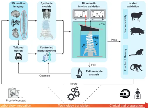
micro- and nanotechnology, calls for novel insights and valida-tion methods before industrializavalida-tion. In this work, we propose a translational framework that leverages recent progress in medical imaging, materials science and engineering, and manufacturing to critically advance the development of clinically relevant bio-electronic devices. The approach is applicable to any medical tech-nology that would benefit from biomimetic implants (Figure 1).
We identified and interlinked four steps of design, fabrication, biomimetic in vitro validation, and in vivo evaluation in large animal models that constitute the technological translation fol-lowing laboratory innovation. Modern imaging techniques, e.g., computed tomography (CT) or magnetic resonance imaging (MRI) offer volumetric data acquisition of biological organs or tissue, and computation of anatomically relevant 3D renderings. Rapid prototyping methods such as 3D printing coupled with 3D imaging data enable the production of anatomically accurate and
biophysical models of the selected biological tissue.[14,15] The bio-electronic devices can then be tailored to the anatomical models and desired device function using computer aided design (CAD) tools and manufactured using methods that are compatible with quality-control protocols. Next, biomimetic in vitro characteriza-tion of the performance of the bioelectronic device is conducted. The implant is inserted and/or positioned on/in models of the target tissue immersed in a synthetic environment that simu-lates in vivo physiological conditions, namely chemical medium (phosphate buffer solution (PBS)), temperature (37 °C), and bio-mimetic tissue dynamics (bending, stretching, and cycling). The stability of the device performance is then quantified against intended use. Following in vitro validation, the implantable devices are evaluated in vivo for biocompatibility, device function and/or therapeutic use. Each step of the translational framework may trigger failure, iteration and innovation.
We applied this experimental framework to the soft neuro-technology named e-dura, electronic dura mater. e-dura are entirely soft electrode arrays, designed to deliver electrical stimulation to the dorsal roots of the spinal cord (Figure 2). The soft implants include three microfabricated building blocks: a silicone elastomer envelope (poly(dimethylsiloxane), PDMS), stretchable, microcracked gold thin-film interconnects (or tracks),[16] and a platinum–silicone (Pt–PDMS) composite elec-trode coating[17] (Figure 2a). This implant design leverages the similarity in mechanical properties of the silicone elastomer used as carrier material and the dura mater that envelopes the neural tissue of the spinal cord. The stretchable thin-film metallization and soft Pt–PDMS electrode coating maintain the implant mechanical signature close to that of PDMS.
Dr. E. Bézard
Institut des Maladies Neurodégénératives University of Bordeaux
UMR 5293 Bordeaux, France Dr. E. Bézard
CNRS
Institut des Maladies Neurodégénératives UMR 5293 Bordeaux, France
Prof. J. Bloch, Prof. G. Courtine
Defitech Center for Interventional Neurotherapies (NeuroRestore) Department of Neurosurgery
University Hospital of Lausanne (CHUV) University of Lausanne (UNIL)
Lausanne, Switzerland
Figure 1. Conceptual framework for the technological translation of soft, implantable bioelectronics. Quantitative information derived from 3D medical
imaging drives the design of interfaces that are tailored to specific anatomical targets. The same information is used to build synthetic models of the biological environment by leveraging biomimetic materials and rapid prototyping techniques. Implants are microfabricated in a controlled cleanroom environment. Complete interfaces are tested in biomimetic multimodal test benches that recreate as closely as possible the intended use of the inter-face when deployed in the body. This process highlights failure modes and allows for technology optimization in vitro, prior to any animal use. Once it performs satisfactorily in vitro, the technology is tested in vivo to validate system-level biocompatibility, device function and/or therapeutic efficacy.
We scaled e-dura implants originally developed for rats[5] to nonhuman primates (NHP), and designed adapted tools for their surgical insertion. e-dura was first demonstrated in the form of subdural implants surgically inserted in rat models of spinal cord injury, and enabled restoration of locomotion by activation of specific motor neuron pools. A subdural implant offers the advantage of minimal shunting of the stimulation electrical currents by the cerebrospinal fluid and steady posi-tion of the electrodes on the pial surface of the spinal cord and roots.[18] This is however at the expense of a complex surgical
procedure, especially durotomy and postimplantation seal of the dura incisions, and potential risks of postsurgical complications. In view of translating our finding, we opted herein for epidural positioning in NHPs. NHP models combine most of the chal-lenges involved in neuroprosthetic applications for humans, including large anatomical structures, demanding mechanical environments, delicate surgical procedures and similarities in the organization and properties of the central nervous system.[19]
Dimensional scaling is a mandatory design step to adapt the electrode footprint and layout to the anatomical structures
Figure 2. Technological translation of e-dura implants. a) Exploded diagram of an e-dura (electrode array). Insets: SEM images of 35 nm Au thin film
on PDMS (elastic interconnect) and Pt–PDMS composite electrode coating. Scale bars: 1 μm. b) Segmentation of high-resolution MRI and CT images enables a 3D reconstruction of the spinal cord in nonhuman primates and rats. c) Photograph of an e-dura connected via a suture wire to the soft insertion tool. Inset: Details of the silicone-embedded stainless-steel grid and suture. Scale bars: 1 cm. d) Photograph of a 4″ silicon wafer silicone-on-silicon (SoS) process. e) Standard deviation on the impedance modulus at three selected frequencies for electrode batches from subsequent process generations. Red data points: device yield. f) Cathodic charge injection capacity (CIC) limit as a function of the geometrical surface area (GSA) of platinum electrodes. Red data points: platinum foil (adapted from Green et al.[20]). Curves: GSA−0.5 fit of the data points; shaded areas: 95% confidence
intervals of the fit. Black data point: previously reported Pt–PDMS.[5] g) Voltage transient curves for three current amplitudes (1, 2, and 10 mA), at a
pulsewidth of 0.3 ms. Data points: mean, n = 31 electrodes; shaded areas: standard deviation. Inset: Details of the electrode polarization during the interphase delay for extraction of the electrode–electrolyte interface polarization.
of NHP and ultimately humans. For example, a comparative analysis of the spine anatomy of the rat and the nonhuman primate (e.g., macaca fascicularis monkey) reveals an overall dimensional increase from the millimeter to centimeter scale (Figure 2b). The outer dimensions of the implant and the geom-etry of neural interfacing electrodes therefore scale accordingly to target larger anatomical structures: the thickness and length of scaled e-dura were in the range of 0.35–0.45 and 5–8 cm, respectively, depending on the addressed spinal segments. Because of the built-in compliance of e-dura, we designed and manufactured a dedicated implantation tool (Figure 2c) that guides the insertion and positioning of the soft implant in the epidural space. The tool was optimized against its shape, stiff-ness, safety and ease of connection/disconnection to e-dura.
Next, we transferred the fabrication of the soft implants to a well-controlled environment compatible with statistical pro-cess control and quality management, so that manufacturing yield and variability can be monitored. Scaled e-dura implants were batch-prepared in a class 100 cleanroom environment by using a combination of microfabrication processes adapted to soft materials. Wafer-level steps were employed throughout the manufacturing of the implants, in what we term a silicone-on-silicon (SoS) process on 4″ wafers (Figure 2d). Patterning resolution was defined by the laser micromachining capability (femtosecond excimer laser), which offered a minimum feature size of about 100 μm when processing ≈250 μm thick silicone layers. Finally, scaled implants were interfaced via a miniatur-ized soft connector to bundled wire leads, that are subcutane-ously threaded and contacted with the electrical stimulation hardware. Details of the process steps and cable assembly are available in the supporting information (Figures S1 and S2 and Table S1, Supporting Information).
Figure 2e highlights the advantages of the SoS process: a tenfold reduction on the standard deviation of electrode imped-ance modulus at 1 kHz compared to the fully manual process, and a device yield of about 75%. These iterative improvements proved critical to the development of a fully controlled manu-facturing environment for the soft, microfabricated implants (Figure S5, Supporting Information).
Efficiency and electrochemical safety of the electrical stim-ulation are secured by high charge injection capacity (CIC) and low interface polarization (Emc) at the electrode–tissue interface, respectively. Figure 2f illustrates the scaling effect on the cathodic CIC limit for the established Pt foil electrode technology[20] and the soft e-dura Pt–PDMS composite, upon stimulation with charge-balanced, cathodic-leading biphasic current pulses (0.3 ms pulse width). The charge that a specific technology can safely deliver during stimulation pulses in vitro does not scale linearly with the electrode surface area. Instead, the CIC decreases as the geometrical surface area (GSA) of the electrode increases (Figure S4, Supporting Information).[21] This is due to nonuniform current distributions across the electrode surface area, which are exacerbated for large electrodes and con-fine the charge injection mechanisms to the periphery of the electrodes.[22] Such a perimeter effect has been shown to be tech-nology-independent[21] and motivates further optimization of the electrochemical performance of the electrode material. The soft Pt–PDMS composite as first reported[5,17] exhibited similar charge injection properties as platinum foil[20] (≈60 μC cm−2 for
0.07 mm2 GSA), balancing the mechanical compliance of sili-cone with the electrochemical properties of platinum particles. In the scaling process, the electrochemical surface area available to mediate charge injection between the electronic conductor and the ionic medium was increased by using smaller Pt parti-cles (0.27–0.47 μm nominal diameter). By further adjusting the platinum filler concentration from 65% to 70% in weight in the PDMS matrix, electrodes with GSA = 0.7 × 2 mm2 exhibited an increased cathodic CIC limit in vitro higher than 200 μC cm−2 for 0.3 ms pulses. The optimized formulation of the Pt–PDMS electrode coating enables high current injection with low inter-face polarization, as shown in the voltage transient curves of Figure 2g. High current pulsing (Imax= 10 mA at 0.3 ms pulse width, corresponding to a charge density of 214 μC cm−2) pro-duced a mean interface polarization within the cathodic water electrolysis limit of −0.6 V for platinum against Ag|AgCl.[22]
The average impedance spectrum of the electrodes displays a flat resistive signature (|Z| ≈ 1 kΩ from about 100 Hz upward) and a large interface capacitance, typical of the Pt–PDMS coating and visible only at the lower end of the probed frequency spec-trum (Figure S3, Supporting Information; n = 58 electrodes). Impedance measurements were used as benchmark metric for all the subsequent validation steps.
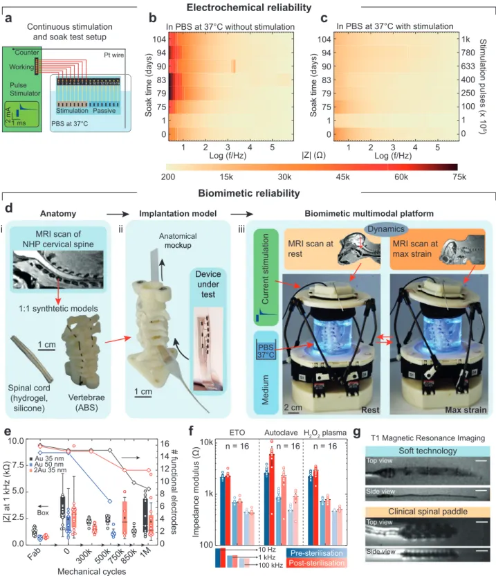
Next, test electrodes were immersed in PBS solution at 37 °C (Figure 3a) and used for continuous stimulation (monophasic capacitor-coupled, charge-balanced waveform,[22] with 0.3 ms cathodic pulse width, 2 mA amplitude, i.e., ≈42 μC cm−2 per phase, at an accelerated pulse rate of 400 Hz). The soft tech-nology was able to deliver 1 billion pulses without registering significant change in electrochemical properties (Figure 3b). Passive (nonstimulated) electrodes included on the same test sample exhibited an increased low-frequency impedance modulus (Figure 3c), suggesting passivation of the electrode surface, which has been shown to be reversed by rejuvenation stimulation protocols.[23,24] The observed increase in the imped-ance modulus is a useful indication that the ingress of conduc-tive species in the silicone substrate and encapsulation is neg-ligible for the duration of the test (slightly above 3 months in total).
Next, we designed and built a biomimetic, multimodal in vitro instrument that applies simultaneous mechanical and electrical stimuli in a temperature-controlled environment (Figure 3d). The platform was designed to mimic the mechan-ical environment of the cervmechan-ical segments of the nonhuman primate spinal cord; the neck region was chosen as this is the segment of the vertebral column that experiences the most demanding mechanical strain. Following our experimental framework (Figure 1), CT and MRI scans of a macaca fascicu-laris were acquired to build models of the vertebrae and spinal cord, respectively, and prepare synthetic mock-ups. Replicas of the cervical vertebrae were 3D-printed and assembled to form an artificial spine. A model of the spinal cord was reproduced using a molded hydrogel enveloped in a thin silicone “dura mater” (Figure 3di). Scaled e-dura implants were next “sur-gically” inserted into the anatomical mock-up (Figure 3dii), immersed in PBS at 37 °C, and interfaced with electrochem-ical stimulation and characterization equipment. We comple-mented this approach by integrating biomimetic materials and dynamics. CT scans were acquired at rest and maximum
Figure 3. Multimodal and biomimetic in vitro characterization. a) Schematic diagram of the setup for continuous stimulation and soak test
(charge-balanced, capacitor-coupled current pulses (2 mA amplitude, 0.3 ms cathodic pulsewidth, 400 Hz)). b,c) Evolution of the electrochemical properties of electrodes subjected to continuous stimulation and passive soaking in PBS at 37 °C (y-axis: time (days), x-axis: frequency (log scale), color maps: impedance modulus, mean of n = 8 electrodes in each plot). d) In vitro biomimetic multimodal platform. e) Multimodal reliability test results from three interconnect variants: Au 35 nm, 16 electrodes; Au 50 nm, 15 electrodes; 2Au 35 nm, 16 electrodes. Boxplot: Impedance modulus at 1 kHz (box band: second quartile; whiskers: standard deviation). Diamond data points: functional electrode count. f) Impedance modulus following sterilization with three techniques (ethylene oxide (ETO), autoclave, and H2O2 plasma). Bar level: mean, horizontal line: median, error bars: standard deviation,
n = 16 electrodes per test. g) MRI scans of an e-dura and a clinical spinal stimulation electrode array. Sequence: T1. Scale bars: 1 cm.
strain postures in order to record 3D positions of the spine during physiological movements of the NHP. The extracted coordinates were used to design a Stewart platform that rep-licated the natural 3D displacements of the cervical segments in NHP. Upon actuation of the Stewart platform, biomimetic multi-axial strains were then applied to the spine mock-up and the implant inserted “epidurally” in the model (Video S1, Sup-porting Information).
We used the biomimetic platform to screen three different Au track variants: standard microcracked Au interconnect tech-nology (1Au 35 nm), a thicker Au interconnect (1Au 50 nm), and interconnects fabricated with a “2Au” process (a gold film was deposited not only on the PDMS substrate but also on the PDMS encapsulation membrane, leading to a metallization of 2 × 35 nm in thickness). Despite a lower impedance at 1 kHz, 1Au 50 nm interconnects proved least robust to multi-modal ageing, with electrode failure appearing between 500k and 750k mechanical cycles (Figure 3e). On the other hand, the 2Au process provided improved mechanical reliability (12 out of 16 functional electrodes at 1 million mechanical cycles compared to 9 out of 16 for 1Au) and reduced mean impedance modulus (≈670 Ω at 10 kHz, n = 30 electrodes, compared to ≈1075 Ω for 1Au, n = 28 electrodes; Figure S6, Supporting Information). In the 2Au design, both microcracked gold layers come into contact, effectively acting as two parallel tracks (Figure S6, Supporting Information). This led both to reduced track resistance and back-up electrical paths that mitigate failures (Figure S7, Sback-upporting Information).
The multimodal and biomimetic in vitro characterization led to substantial improvements in the e-dura neurotechnology, by enabling both more reliable functionality validation compared to standard in vitro test protocols, and more efficient and faster development cycles compared to in vivo tests. Standard testing such as pull test and uniaxial cycling failed to detect the issues reported above. Following these results, the 2Au technology was chosen to prepare e-dura for subsequent in vivo evaluation.
Next, we assessed the compatibility of the scaled e-dura with three clinical sterilization methods, namely, ethylene oxide (ETO) vapor, autoclave, and hydrogen peroxide plasma. The com-parison of impedance spectra and representative scanning elec-tron microscopy (SEM) scans (Figure 3f; Figure S8, Supporting Information) pre- and poststerilization shows that both ETO and H2O2 plasma had minimal impact on the electrochemical perfor-mance and the topography of the electrodes, while the autoclave test shows an increase in the impedance modulus above 10 Hz that held with resistive-like phase until high frequency. This suggests an increase in the interconnect resistance rather than deterioration of the electrode coating, likely due to the prolonged exposure to high temperature.[25] These results suggest that steri-lization did not significantly affect the implant functionality.
We also imaged a complete e-dura implant inserted in a gelatin phantom model in a 3 T clinical MRI scanner, using T1- (Figure 3g) and T2- (Figure S9, Supporting Information) weighted sequences. Compared to a standard paddle electrode array for spinal stimulation, the e-dura implant does not induce significant imaging artefacts that can hinder the visualization of the immediate surrounding tissue, although electrode con-tacts are clearly visible. MRI artefacts are generated due to the mismatch in magnetic susceptibility of the imaged materials.
Contrary to silicone, gold, and platinum have very different mag-netic susceptibilities compared to the water contained in the phantom.[26] The thin film form factor of the gold interconnect and the dispersion of platinum particles in the PDMS matrix mitigate however the effective mismatch, and therefore reduce the size of the artefact generated during the MRI acquisition. The bulk metal elements embedded in the clinical electrode array, on the other end, create large imaging artefacts around the entire device.
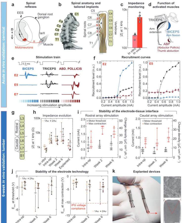
The fourth step of the translational framework focuses on the in vivo evaluation of the scaled neurotechnology. Efficacy of the soft electrodes was assessed intraoperatively, followed by a long-term stability monitoring experiment during 6-week-long implantation. We designed e-dura implants to deliver epidural electrical stimulation (EES) targeting the dorsal roots of the spinal cord, in order to recruit proprioceptive circuits. This stim-ulation elicits reflex responses that enable motor control of arm and leg muscles (Figure 4a).[27–29]
To assess the efficacy of the soft e-dura electrodes, we con-ducted a functional evaluation of arrays surgically inserted in the epidural space of the spinal cord, recording muscle reflex responses following electrical stimulation. Experiments were conducted on 3 macaca fascicularis monkeys kept in deep anes-thesia. We mapped the position of the electrodes to the anatom-ical position of the posterior roots innervating the targeted seg-ments of the spinal cord, which we measured in each subject. Figure 4b displays a representative example of an e-dura layout overlaid on the C5 to T1 roots of the cervical spinal cord. Elec-trode impedance across all implants are comparable and display a threefold increase in modulus (at 1 kHz) in vivo, accounting for the tissue interface (Figure 4c). Trains of current-controlled EES delivered through the electrodes elicited reflex responses that we monitored from electromyogram (EMG) signals. Increase in EES amplitude led to graded increase in reflex response amplitudes, also called recruitment curves (Figure 4d,e). Recruitment curves calculated from raw EMG responses to single EES pulses high-light a clear selectivity in the activation of muscles with distinct motor functions in the forelimb (animal Mk-Cs, cervical array; Figure 4f). The repeatability of these observations was confirmed by replicating the experiment in three independent sessions with three different animals, with consistent results obtained (ani-mals Mk-Cs, Mk-Ca, and Mk-Li; Figure S10, Supporting Infor-mation). These findings are in agreement with anatomical inner-vation maps of the primate forelimb,[30] which show that the cervical spinal cord is naturally organized with the biceps and triceps predominantly innervated through spinal roots C6 and C8, respectively.
Next, we evaluated the stability and performance of the implants during 6-week-long implantation. Scaled lumbar implants (fitting the L4 to L7 vertebral segments) were prepared and monitored in vivo for an implantation period of six weeks (Figure 4g). e-dura implants were produced with designs com-prising alternating single (1Au) and double (2Au) gold tracks to the soft Pt–PDMS electrodes that were implanted over the lumbar spinal cord of two monkeys (NHP4 and NHP5), for a total of four electrodes per technology variant and per animal (Figure S11, Supporting Information). Stimulation and electro-chemical characterization of the electrodes were conducted in vitro before ETO sterilization, in vivo intraoperatively, 15 and
Figure 4. In vivo evaluation of the soft neurotechnology. a) Presynaptic activation of motoneurons through electrical neuromodulation of
propriocep-tive feedback circuits leads muscle activation. b) CT reconstruction of the vertebral column of a macaca fascicularis and associated overlay of an e-dura implanted in the cervical epidural space. c) Impedance modulus at 1 kHz in vitro (PBS) and in vivo (bars: mean, error bars: standard deviation, n = 7
43 days after implantation, by accessing a subcutaneous con-nector, and finally in vitro post explanation. In vivo, current-controlled stimulation was tested through each of the implanted electrodes to elicit motor response. Impedance measurements acquired at each time point (Figure 4h) confirm full function-ality of the e-dura electrodes throughout the duration of the 6-week experiment.
The stability of the electrode–tissue interface, which does not depend on the Au track technology, was quantified at each time point in vivo by evaluating the minimum stimulation current at which motor responses were visually detected (threshold), and the current amplitude at which the motor responses saturated (max-imum contraction, no increased response detected by increasing further the stimulation amplitude or excessive contractions desta-bilizing the animal). The threshold and maximum contraction currents showed no visible change between week 2 and week 6 (Figure 4i), suggesting the electrode–tissue interface is stable.
Cathodic polarization during stimulation, i.e., the measure of the minimum voltage required to elicit the desired electrophysi-ological function, was also monitored over time. This is a critical metric for neuromodulation applications, which rely on implant-able electronic hardware powered with limited voltage batteries (around 10 V). Figure 4j shows that in vivo, the minimum cathodic polarization displayed a voltage that is both stable across the time points, and lower than 10 V in most cases, even at maximum contraction (right plot). These results also confirmed that the 2Au technology offered consistently lower polarization, leaving more margin in case of gradual impedance drift over longer implantation periods.
At 6-week post implantation, e-dura implants were explanted easily from the epidural space following a dissection of the fibrotic tissue surrounding the cable at the entrance of the lami-nectomy. Explanted electrodes were still functional with similar properties as pre-implantation (Figure S12, Supporting Informa-tion). Figure 4k shows a photograph of the electrode arrays and SEM scans of the Pt–PDMS coating after explanation. Neither damage nor tissue encapsulation are evident.
The validation of the combined four steps (design, manu-facturing, in vitro biomimetic validation, and in vivo functional evaluation) represent essential requirements to bring forward proof-of-concept prototypes to translational study that can next be used to explore novel therapies. We found this integration effort is not a mere opportunity to assemble steps together but rather triggers further and essential innovation. To lower the soft electrode impedance and deliver efficient neural stimulation, we optimized the formulation of the soft Pt–PDMS electrode coating (Figure 2f). We developed soft metallization with low electrical
resistance through a new process of mirroring the stretchable conductors that now complies with the electrical requirements of implantable stimulation hardware (Figure S6, Supporting Infor-mation). To extend in vitro validation to biomimetic testing, we designed and implemented a new multimodal in vitro instru-ment that facilitates concurrent electrochemical and mechanical ageing, and electrochemical and electrical monitoring of the soft electrode implant (Figure 3d). The epidural positioning of the scaled e-dura implants offered a high surgical safety while still ensuring selectivity of the neurostimulation protocols (Figure 4d).
The translational steps presented herein, however, are not exhaustive and further work is required to build a complete case for clinical translation. In vitro, it is important to monitor the corrosion and the release of coating material due to elec-trical stimulation, as these effects could both limit the lifetime of the electrodes and prove harmful to the tissue. Impact resist-ance and long-term electrical insulation tests should also be included in the characterization protocols. Furthermore, the transfer to medical grade materials may be required toward clinical translation. Future packaging and integration solu-tions linking standard implanted electronics (rigid casing with feedthroughs), through leads or ribbon cables, to the soft neural interfaces must offer adequate electro-mechanical stability and reliability, hermeticity, and biointegration properties to warrant adoption into clinical practice. For soft bioelectronics, bio-compatibility and histology tests are also required to confirm the superior biointegration properties triggering lower immune response compared to state-of-the-art implants.[31,32] In the case of epidural electrodes, there is no penetration by foreign mate-rial within the neural tissue. We only expected encapsulation of the implant by fibrotic tissue build-up. Explanation of the implants from the epidural space after 6 weeks only required dissection of fibrotic tissue that had formed around the cables outside the spine, while the electrode arrays were easily slid out from the epidural space. Optical inspection of the explanted arrays after saline, ethanol and deionized water rinsing revealed no major biological residue on their surface (Figure 4k; Figure S12a,d, Supporting Information).
Finally, it is worth noting that while mandatory, the proposed experimental framework is a resource intensive and challenging commitment that requires a dedicated interdisciplinary team of neuroengineers, neuroscientists, and neurosurgeons.[33] Although many aspects in the translation of implantable soft bio-electronics remain unsolved challenges, this work shows that an integrated methodology, from design to in vivo evaluation, can uncover needs for technical advances, and help projecting lab-based innovation toward translational and ultimately clinical use.
electrodes). d) Diagrams and function of the muscles activated by epidural electrical stimulation. e) Electromyographic signals recorded in the biceps, triceps, and abductor pollicis following stimulation using electrodes E2, E5, and E7. The color code for the curves corresponds to the different current amplitudes used for EES. f) Recruitment level based on the electromyographic activity recorded on the activated muscles (each data point corresponds to an individual trial out of a total of four trials per current amplitude per electrode). g) Schematic of e-dura implanted in the lumbar epidural space. h) Evolution over time of the impedance at 1 kHz for all the electrodes classified by track technology (horizontal bars: mean, whiskers: min–max, n = 8 electrodes per technology, x: 1 missing measurement). i) Stimulation current over time at threshold (black) and maximum (red) muscle contraction. Left graph: NHP4, rostral placement (L4–L5), n = 8 electrodes, GSA = 1.4 mm2; right graph: NHP5, caudal placement (L6–L7), n = 8 electrodes, GSA =
1.4 mm2; horizontal lines: mean, whiskers: min–max. j) Evolution of the minimum cathodic polarization of the electrodes during current-controlled
stimulation at threshold and maximum contraction amplitudes. Electrodes are classified by track technology. Left graph: threshold, n = 8 electrodes; right graph: maximum contraction, n = 8 electrodes; horizontal lines: mean, whiskers: min–max, x: 1 missing measurement. k) Photograph of e-dura after explanation and rinsing in PBS, ethanol, and deionized water, and drying in air. Insets: SEM scans of one of the explanted electrodes. Scale bars: top, 2 μm; bottom, 200 μm.
Experimental Section
Experimental details and methods are available in the Supporting Information.
Supporting Information
Supporting Information is available from the Wiley Online Library or from the author.
Acknowledgements
F.F., X.K., G.C. and M.C. contributed equally to this work. The authors would like to acknowledge financial support from the Bertarelli Foundation, the European Union’s Horizon 2020 Research and Innovation Programme under the Marie Skłodowska-Curie grant agreement no. 665667 to G.S., the Wyss Center for Bio- and Neuroengineering [WCP008], a Whitaker foundation fellowship to I.S., and the Swiss National Science Foundation including a Sinergia subside CRSII3_160696, a Sino-Swiss Science and Technology Cooperation subside [IZLCZ3_156331], an Ambizione Fellowship (No. 167912 to M.C.), and the National Center of Competence in Research (NCCR) in Robotics. The authors would like to thank Prof. Eric Rouiller for his support at the Platform of Translational Neuroscience of the University of Fribourg, Prof. Luc Stoppini and his team (HEPIA, Geneva) for their help with the ETO sterilization; Mélanie Kaeser and Alexandra Hickey for animal care; Florian Lanz and Eric Schmidlin for their help with anesthesia; the staff at Sim4Life by ZMT, www.zurichmedtech.com, for their support with the construction of the anatomical models; Jelescu Ileana, Yin Ting, and Ipek Özlem for their help with the MRI scans of rats; André Mercanzini and Pascal Harbi of Aleva Neurotherapeutics SA for providing the stimulation hardware used for in vitro validation; and the staff at the Neural Microsystems Platform of the Wyss Center for Bio and Neuroengineering for their help with the fabrication processes.
Acute electrophysiology experiments: Surgical and behavioral procedures
were approved by the local ethical committee in accordance with the guidelines for the Care and Use of Laboratory Animals and approved by local (Canton of Fribourg) and federal (Swiss) veterinary authorities with authorization numbers 2014_42E_FR (Mk-Ca), 2017_03_FR (Mk-Li), 2017_04E_FR (Mk-Cs).
Six-week implantation experiments: Experiments were approved by the
Institutional Animal Care and Use Committee of Bordeaux (CE50, France) and performed in accordance with the European Union directive of 22 September 2010 (2010/63/EU) on the protection of animals used for scientific purposes in an AAALAC-accredited facility (Chinese Academy of Science, Beijing, China).
Conflict of Interest
S.P.L., G.C., J.B., M.C., and N.V. hold various patents in relation to the present work. S.P.L., G.C., and J.B. are founders and shareholders of GTX medical, a company developing an EES-based therapy to restore locomotion after spinal cord injury.
Keywords
biomimetic materials, multimodal characterization, neural implants, soft electrodes
[1] G. Schiavone, S. P. Lacour, Sci. Transl. Med. 2019, 11, eaaw5858. [2] D.-H. Kim, J. Viventi, J. J. Amsden, J. Xiao, L. Vigeland, Y.-S. Kim,
J. A. Blanco, B. Panilaitis, E. S. Frechette, D. Contreras, D. L. Kaplan, F. G. Omenetto, Y. Huang, K.-C. Hwang, M. R. Zakin, B. Litt, J. A. Rogers, Nat. Mater. 2010, 9, 511.
[3] D. Khodagholy, J. N. Gelinas, T. Thesen, W. Doyle, O. Devinsky, G. G. Malliaras, G. Buzsáki, Nat. Neurosci. 2015, 18, 310.
[4] M. T. Alt, E. Fiedler, L. Rudmann, J. S. Ordonez, P. Ruther, T. Stieglitz,
Proc. IEEE 2017, 105, 101.
[5] I. R. Minev, P. Musienko, A. Hirsch, Q. Barraud, N. Wenger, E. M. Moraud, J. Gandar, M. Capogrosso, T. Milekovic, L. Asboth, R. F. Torres, N. Vachicouras, Q. Liu, N. Pavlova, S. Duis, A. Larmagnac, J. Vörös, S. Micera, Z. Suo, G. Courtine, S. P. Lacour,
Science 2015, 347, 159.
[6] C. Dagdeviren, K. B. Ramadi, P. Joe, K. Spencer, H. N. Schwerdt, H. Shimazu, S. Delcasso, K. Amemori, C. Nunez-Lopez, A. M. Graybiel, M. J. Cima, R. Langer, Sci. Transl. Med. 2018, 10, eaan2742.
[7] C. M. Boutry, L. Beker, Y. Kaizawa, C. Vassos, H. Tran, A. C. Hinckley, R. Pfattner, S. Niu, J. Li, J. Claverie, Z. Wang, J. Chang, P. M. Fox, Z. Bao, Nat. Biomed. Eng. 2019, 3, 47.
[8] A. B. Ajiboye, F. R. Willett, D. R. Young, W. D. Memberg, B. A. Murphy, J. P. Miller, B. L. Walter, J. A. Sweet, H. A. Hoyen, M. W. Keith, P. H. Peckham, J. D. Simeral, J. P. Donoghue, L. R. Hochberg, R. F. Kirsch, Lancet 2017, 389, 1821.
[9] D. D. Zhou, J. D. Dorn, R. J. Greenberg, in 2013 IEEE Int. Conf. on
Multimedia and Expo Workshops (ICMEW), IEEE, Piscataway, NJ, USA
2013, https://doi.org/10.1109/ICMEW.2013.6618428.
[10] C. Pollo, A. Kaelin-Lang, M. F. Oertel, L. Stieglitz, E. Taub, P. Fuhr, A. M. Lozano, A. Raabe, M. Schüpbach, Brain 2014, 137, 2015.
[11] L. J. Bour, M. A. J. Lourens, R. Verhagen, R. M. A. de Bie, P. van den Munckhof, P. R. Schuurman, M. F. Contarino, Brain Stimul. 2015, 8, 730.
[12] T. Boretius, J. Badia, A. Pascual-Font, M. Schuettler, X. Navarro, K. Yoshida, T. Stieglitz, Biosens. Bioelectron. 2010, 26, 62.
[13] R. K. Shepherd, J. Villalobos, O. Burns, D. A. X. Nayagam, J. Neural
Eng. 2018, 15, 041004.
[14] M. Vukicevic, B. Mosadegh, J. K. Min, S. H. Little, JACC Cardiovasc.
Imaging 2017, 10, 171.
[15] V. Bagaria, R. Bhansali, P. Pawar, J. Clin. Orthop. Trauma 2018, 9, 207. [16] S. P. Lacour, S. Wagner, Z. Huang, Z. Suo, Appl. Phys. Lett. 2003, 82,
2404.
[17] I. R. Minev, N. Wenger, G. Courtine, S. P. Lacour, APL Mater. 2015,
3, 014701.
[18] M. Capogrosso, J. Gandar, N. Greiner, E. M. Moraud, N. Wenger, P. Shkorbatova, P. Musienko, I. Minev, S. Lacour, G. Courtine,
J. Neural Eng. 2018, 15, 026024.
[19] S. Camus, W. K. D. Ko, E. Pioli, E. Bezard, Neurobiol. Learn. Mem.
2015, 124, 123.
[20] R. A. Green, H. Toor, C. Dodds, N. H. Lovell, Sens. Mater. 2012,
24, 165.
[21] M. Ganji, A. Tanaka, V. Gilja, E. Halgren, S. A. Dayeh, Adv. Funct.
Mater. 2017, 27, 1703019.
[22] S. F. Cogan, Annu. Rev. Biomed. Eng. 2008, 10, 275.
[23] M. D. Johnson, K. J. Otto, D. R. Kipke, IEEE Trans. Neural Syst.
Rehabil. Eng. 2005, 13, 160.
[24] K. J. Otto, M. D. Johnson, D. R. Kipke, IEEE Trans. Biomed. Eng. 2006,
53, 333.
[25] Y. Zhao, M. Yu, Z. Liu, Z. Yu, J. Appl. Phys. 2019, 125, 165305. [26] M. C. Wapler, J. Leupold, I. Dragonu, D. von Elverfeld, M. Zaitsev,
U. Wallrabe, J. Magn. Reson. 2014, 242, 233.
[27] M. Capogrosso, N. Wenger, S. Raspopovic, P. Musienko, J. Beauparlant, L. Bassi Luciani, G. Courtine, S. Micera, J. Neurosci.
2013, 33, 19326.
[28] C. A. Angeli, M. Boakye, R. A. Morton, J. Vogt, K. Benton, Y. Chen, C. K. Ferreira, S. J. Harkema, N. Engl. J. Med. 2018.
[29] F. B. Wagner, J.-B. Mignardot, C. G. L. Goff-Mignardot, R. Demesmaeker, S. Komi, M. Capogrosso, A. Rowald, I. Seáñez, M. Caban, E. Pirondini, M. Vat, L. A. McCracken, R. Heimgartner, I. Fodor, A. Watrin, P. Seguin, E. Paoles, K. V. D. Keybus, G. Eberle, B. Schurch, E. Pralong, F. Becce, J. Prior, N. Buse, R. Buschman, E. Neufeld, N. Kuster, S. Carda, J. von Zitzewitz, V. Delattre,
T. Denison, H. Lambert, K. Minassian, J. Bloch, G. Courtine, Nature
2018, 563, 65.
[30] A. B. Jenny, J. Inukai, J. Neurosci. 1983, 3, 567.
[31] S. P. Lacour, G. Courtine, J. Guck, Nat. Rev. Mater. 2016, 1, 16063.
[32] A. F. Renz, A. M. Reichmuth, F. Stauffer, G. Thompson-Steckel, J. Vörös, J. Neural Eng. 2018, 15, 061001.
[33] G. Courtine, J. Bloch, Neuron 2015, 86, 29.