Publisher’s version / Version de l'éditeur:
Proceedings of the Eighteenth International Conference on Surface Modification
Technologies
READ THESE TERMS AND CONDITIONS CAREFULLY BEFORE USING THIS WEBSITE. https://nrc-publications.canada.ca/eng/copyright
Vous avez des questions? Nous pouvons vous aider. Pour communiquer directement avec un auteur, consultez la
première page de la revue dans laquelle son article a été publié afin de trouver ses coordonnées. Si vous n’arrivez pas à les repérer, communiquez avec nous à PublicationsArchive-ArchivesPublications@nrc-cnrc.gc.ca.
Questions? Contact the NRC Publications Archive team at
PublicationsArchive-ArchivesPublications@nrc-cnrc.gc.ca. If you wish to email the authors directly, please see the first page of the publication for their contact information.
NRC Publications Archive
Archives des publications du CNRC
This publication could be one of several versions: author’s original, accepted manuscript or the publisher’s version. / La version de cette publication peut être l’une des suivantes : la version prépublication de l’auteur, la version acceptée du manuscrit ou la version de l’éditeur.
Access and use of this website and the material on it are subject to the Terms and Conditions set forth at
Residual stress analysis of laser cladded Al/Si coatings onto aluminium
alloy substrate
Dubourg, L.; Hlawka, F.; Cornet, A.
https://publications-cnrc.canada.ca/fra/droits
L’accès à ce site Web et l’utilisation de son contenu sont assujettis aux conditions présentées dans le site
LISEZ CES CONDITIONS ATTENTIVEMENT AVANT D’UTILISER CE SITE WEB.
NRC Publications Record / Notice d'Archives des publications de CNRC:
https://nrc-publications.canada.ca/eng/view/object/?id=fefc86aa-147f-4388-8d27-dc5417cf573c https://publications-cnrc.canada.ca/fra/voir/objet/?id=fefc86aa-147f-4388-8d27-dc5417cf573c
Residual Stress Analysis of Laser-cladded Al/Si Coatings onto Aluminium Alloy Substrates
L. DUBOURGa,1, F. HLAWKAb, A. CORNETb
a Aluminium Technology Centre, National Research Council Canada, 501, Boul. de l'Université, Saguenay (Québec) G7H
8C3 Canada. E-mail: laurent.dubourg@cnrc-nrc.gc.ca
b Laboratoire d’Ingénierie des Surfaces de Strasbourg, ENSAIS, 24 bd de la victoire, 67000 Strasbourg, France. E-mail:
f.hlawka@insa-strasbourg.fr
1
Corresponding author: Tel. +1 418 545-5098; Fax +1 418 545-5345 (L. Dubourg)
ABSTRACT
Laser cladding process causes thermal stresses, which lead to the appearance of residual stresses and substrate distortions. In this study, laser cladding was applied to a 5052 aluminium alloy using a cw Nd:YAG laser and coaxial injection of Al 50Si powders. Residual stresses were quantified by X-ray diffraction and by sample strain measurements. The differences in the results obtained by these two methods highlighted the influence of the heat-affected zone. A model of three strain domains has explained these differences: the coating, the HAZ and the substrate. Experiments identified an optimal treatment speed, leading to maximum compression stresses. Moreover, at a certain fixed speed, thermal stresses balanced each other in the sample leaving the substrate undistorted.
KEYWORDS: laser cladding, aluminium, residual stresses, strain method, XRD stress measurement. 1.0 INTRODUCTION
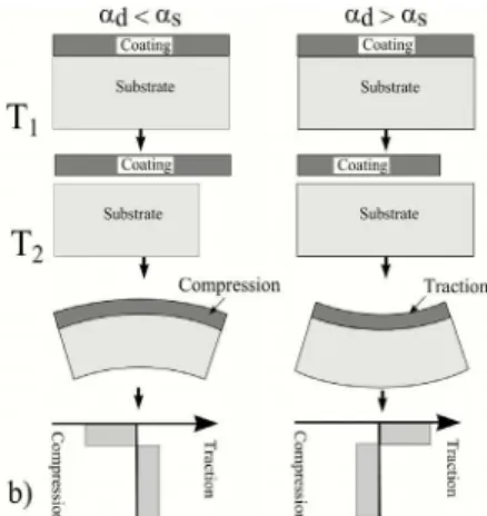
As with other high energy surface treatments, laser cladding creates thermal stresses that can result in residual stresses and eventually distort the sample. According to Sue et al., [1], the residual stresses can be modeled using the sum of intrinsic and thermal stresses. The intrinsic stresses correspond to the structural modifications of the material during treatment. In the case of laser cladding, a high energy process, thermal stresses predominate. They are generated by the difference in contraction during cooling between the coating and the substrate (Fig. 1). The coating has the same dimension as the substrate during treatment (temperature T2). During cooling to
room temperature T1, the substrate contracts more than does the
coating (case where the coefficient of thermal expansion (CTE) of the coating is less than that of the substrate: αd < αs)
resulting in compression stresses in the coating [1].
2.0 EXPERIMENTAL PROCEDURE
The cladding was carried out using a cw 2000 W Nd:YAG laser. The Nd:YAG laser was chosen based on the fact that the aluminium substrate has an absorption coefficient at this wavelength twice that of the CO2 laser [2]. A 300 mm focal length lens was used to focus the beam. The laser power was 1700
W on the workpiece and the diameter circular beam on the sample was 2.7 mm. The composition of the powder used was Al 50Si (wt.%) with a grain size between 45 and 90 µm. These coatings were the subject of a metallographic study conducted by Pei et al. [3]. The powder was injected at rates varying from 5 to 14 g.min-1. The samples were placed on an X-Y stage that moved under the beam at scanning speeds varying from 0.7 to 1.6 m.min-1. The substrates were made from a commercial aluminium alloy 5052 (Al + 3 wt.% Mg) and measured 75 x 8 x 6 mm3. We chose this non-hardenable alloy in order to minimise the intrinsic stresses and to analyse particularly the effects of thermal stresses. The samples were then annealed at 150°C for 24 hours to relax the residual stresses from rolling. The laser cladding was then produced over the entire length of the substrate. The strain method consisted in measuring sample distortion after laser cladding and calculating overall stresses in the coating. This technique was used by Tomlinson et al. [4] on different aluminium surface alloys produced using a laser (Al-Fe and Al-Cu alloys). In our case, sample distortion was measured using an extended field confocal microscope [5]. The elastic modulus of the coating and substrate were set respectively at 89 and 69 GPa [6]. Moments of inertia were calculated for each sample according to the dimensions of the coating. A similar approach was used by Teixeira et al. [7]. In order to measure
Figure 1: Influence of CTE on the residual stresses
stresses in the depth of coatings, the clads were electrolytically polished with perchloric acid to successively remove material. This method has previously been used on laser surface alloys [8, 9]. Stress was measured along the clad length for the {311} crystal plane of aluminium using a chrome anode (λ = 0.2291 nm). We studied the diffraction peak located at 139.339° (oscillation ± 1°, duration 6 min) [10].
3.0 RESULTS
3.1 Stress Measurements Using the Strain Method
Fig. 2 shows the stress measurements using the strain method, with each point representing one speed/flow pair analysed. The level of residual stress is shown by contour curves and evolves between -160 and 60 MPa. Distortions associated with these stresses correspond to those in Fig. 1: samples with a convex form show a compressive state in the clad and conversely samples with a concave form result from tension in the clad. The following
phenomena can be observed. (i) Results obtained using the strain method disagree with the model in Fig. 1. In our case, the CTE of the coating (αd =
14.10-6 m.m-1.K-1 [6]) is less than that of the substrate (αs = 24.10-6 m.m-1.K-1 [6]). Therefore, according to
Fig. 1, all coatings should be in compression and should show signs of convex distortion, regardless of operating parameters. (ii) Residual stresses increase when the scanning speed increases, moving from a compressive to a tension state. (iii) For low scanning speeds (V ≤ 0.8 m.min-1
), residual compressive stresses increase enormously when the powder feed rate increases (maximum of -151 MPa). (iv) For a speed of approximately 0.9 m.min-1, samples show no distortion, with a zero residual stress level in the coating (black level curve in Fig. 2).
3.2 Stress Measurement Using XRD
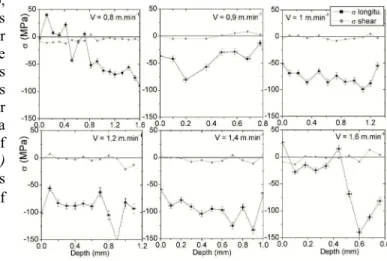
The measurements of longitudinal and shearing stresses carried out by XRD as a function of scanning speed are presented in Fig. 3. Measurements were taken through the depth of each coating at 0.1 mm intervals down to the interface with the substrate. The powder feed rate was set at an intermediate rate of 11 g.min-1. The scanning speed evolved from 0.8 to 1.6 min-1. The following phenomena can be observed. (i) The level of residual longitudinal stresses is relatively stable and always negative in the coating. Whatever the scanning speed, the cladding is systematically in compression. This observation agrees with the model of Fig. 1. Also,
since shearing stresses are always nil, this phenomenon supports the model of linear stresses used in the strain method. (ii) The average residual stress level increases with increasing scanning speed. It evolves by approximately -30 to -110 MPa for speeds of 0.8 to 1.4 m.min-1. However, a decrease is observed on the surface of coating conducted at 1.6 m.min-1. (iii) The greatest average compression stress (σd = -95 MPa) is observed for a speed of
1.4 m.min-1.
4.0 DISCUSSION
Results obtained with these two methods are completely different. The stress level
measured by the strain method is negative, then positive and always increases with increasing scanning speeds. However, the XRD measurement shows compression stresses no matter what the
Figure 2: Residual stress measurement in the coatings (MPa) using the strain method. Influence of the operating parameters: scanning speed (V) and powder feed rate (Q).
speed and a minimum of -95 MPa at 1.4 m.min-1. The measurement scale can explain this difference. In fact, the strain method reveals the overall stress that distorts the whole of the sample, whereas X-ray diffraction measures the local surface stress field. Furthermore, the distortions observed do not coincide with the hypothesis in Fig. 1, namely a convex distortion for αd < αs. These results support
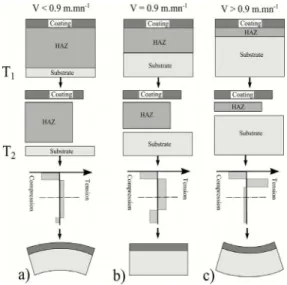
the introduction of the block model proposed by Pilloz et al. [11]. In addition to the coating and the substrate, the authors take into account the Heat Affected Zone (HAZ) (see Fig. 4). This zone corresponds to the part of the sample significantly affected by the heat cycle of the treatment. In the case of aluminium, the HAZ reaches a critical temperature beyond which the material is subject to plastic distortions due to thermomechanical effects. The substrate thus corresponds to the zone where the thermal effects of the process are negligible (we
will assume that this block remains at room temperature T1). Fig. 4 illustrates this principle for
various speeds and for a coating with a lower CTE than the substrate (αd < αs). Going from T2 to T1, the
coating therefore contracts less than the HAZ whereas the substrate expected to remain at the same temperature is not subject to expansion. The coating and the substrate are thus always in compression and the HAZ in tension. For a slow scanning speed (V < 0.9 m.min -1 in our case), the HAZ is relatively deep, resulting in an overall state of compression above the average line of the sample and a convex distortion (Fig. 4.a). For a rapid scanning speed (V > 0.9 m.min
-1
), the HAZ is not widespread. The upper part of the sample is entirely in tension and therefore presents a concave distortion (Fig. 4.c). For an intermediate scanning speed (V = 0.9 m.min-1), the field of stresses is balanced through the depth of the sample, resulting in no sample distortion (Fig. 4.b). The block model thus provides an explanation for the divergent phenomena observed using the strain method and XRD.
5.0 CONCLUSION
Residual stresses were measured using two complimentary techniques: the strain method and XRD. The substantial difference in the results from the two techniques allowed us to introduce the block model to explain the phenomena observed. For a certain scanning speed (V = 0.9 m.min-1), the strain method indicated a balance of residual stresses, causing zero distortion of the sample. Likewise for all processing speeds, XRD measurement revealed residual compression stresses in the coatings, which reached a maximum of -95 MPa for a speed of 1.4 m.min-1. We then conclude that the methods are complimentary, and the results obtained will enable us in the future to predict which surfaces will show improved wear and fatigue resistance due to compression constraints and non-distorted coated materials.
6.0 REFERENCES
[1]: A. Sue and G.S. Schajer, Stress determination for coatings, ASM Handbook, vol. 5, ASM OH, USA, (1994) 645-653. [2]: J.C. Jules, J.M. Pelletier, M. Pilloz and A. B. Vannes, Journal de Physique IV, vol. 1 (1991) 61-63.
[3]: Y. T. Pei and J. Th. M. De Hosson, Acta Materialia (2000) 2671-2624.
[4]: W. J. Tomlinson and A. S. Bransden, Surface Engineering, vol. 11 n°4 (1995) 337-344 [5]: J. Cohen-Sabban, Mesure, n°719 (1999) 85-90.
[6]: R. Develay, Techniques de l’Ingénieur, M443 (1989).
[7]: V. Teixeira, M. Andritschky, W. Fischer, and D. Stover, J. of Material Processing Tech., vol. 92-93 (1999) 209-216. [8]: L. Dubourg, F.Hlawka and A.Cornet, Journal de Physique IV, vol. 10 (2000) 137-144.
[9]: M. A. McMahon, K. G. Watkins, M. G. S. Ferreira and R. Vilar, Proc. of ICALEO Orlando, FL (1993) 746-754. [10]: I. C. Noyan, T. C. Huang and B. R. York, Critical review in solid state and materials sci., vol. 20(2) (1995) 125-177. [11]: M. Pilloz, J. M. Pelletier and A. B. Vannes, Journal of Material Science, vol. 27 (1992) 1240-1244.
Figure 5: Hypothesis of the stress field in the samples as a function of the scanning speed: block model with αd < αs.