HAL Id: hal-02086049
https://hal.univ-lorraine.fr/hal-02086049v2
Submitted on 8 Feb 2019
HAL is a multi-disciplinary open access
archive for the deposit and dissemination of
sci-entific research documents, whether they are
pub-lished or not. The documents may come from
teaching and research institutions in France or
abroad, or from public or private research centers.
L’archive ouverte pluridisciplinaire HAL, est
destinée au dépôt et à la diffusion de documents
scientifiques de niveau recherche, publiés ou non,
émanant des établissements d’enseignement et de
recherche français ou étrangers, des laboratoires
publics ou privés.
Independence of spin-orbit torques from the exchange
bias direction in N i 81 F e 19 / IrMn bilayers
Hilal Saglam, J. Carlos Rojas-Sanchez, Sébastien Petit, Michel Hehn, Wei
Zhang, John Pearson, Stéphane Mangin, Axel Hoffmann
To cite this version:
Hilal Saglam, J. Carlos Rojas-Sanchez, Sébastien Petit, Michel Hehn, Wei Zhang, et al.. Independence
of spin-orbit torques from the exchange bias direction in N i 81 F e 19 / IrMn bilayers. Physical
Review B: Condensed Matter and Materials Physics (1998-2015), American Physical Society, 2018, 98
(9), pp.094407. �10.1103/physrevb.98.094407�. �hal-02086049v2�
Materials Science Division, Argonne National Laboratory, Lemont, Illinois 60439, USA
2Department of Physics, Illinois Institute of Technology, Chicago, Illinois 60616, USA 3Institut Jean Lamour, UMR-CNRS 7198, Université de Lorraine, F-54000 Nancy, France
4Department of Physics, Oakland University, Rochester, Michigan 48309, USA
(Received 4 April 2018; revised manuscript received 11 July 2018; published 7 September 2018) We investigated a possible correlation between spin Hall angles and exchange bias in Ni81Fe19/IrMn samples
by performing spin-torque ferromagnetic resonance measurements. This correlation is probed by patterning of Ni81Fe19/IrMn bilayers in different relative orientations with respect to the exchange bias direction. The measured
voltage spectra allow a quantitative determination of spin Hall angles, which are independent of the exchange bias orientation around 2.8 ± 0.3%.
DOI:10.1103/PhysRevB.98.094407
Recently, antiferromagnetic materials have received in-creased interest in spintronics devices beyond their traditional use in exchange bias based applications [1–3]. Antiferromag-nets are magnetically ordered with zero net magnetization, which makes them insensitive to external magnetic fields. For the same reason, they do not produce any magnetic stray fields, which avoids cross-coupling between different devices in close proximity. Furthermore, they have very high characteristic frequencies in the terahertz regime; hence they can operate at high speeds. The discovery of several magnetotransport effects in antiferromagnets such as spin-orbit torques [4], anisotropic magnetoresistance [5,6], spin Seebeck effects [7,8], inverse spin Hall effects [9,10], galvanic effects [4], and efficient spin current transmission [11–13] shows the feasibility of using them as active components for spintronic devices. In particular, the discovery of electrical switching and readout of an antifer-romagnet by spin-orbit torque shows that antiferantifer-romagnets can be controlled electrically in similar ways as their ferromagnetic counterparts [14].
Of particular interest is the possibility to drive the mag-netization dynamics of a ferromagnet using the spin Hall effect [15–18], which generates a spin accumulation on the lateral surface of a charge carrying material. The efficiency of the spin Hall effect is described by the spin Hall angle [19], !SH= 2e¯h(Js/Jc). Using the spin-torque ferromagnetic
resonance technique [20], spin Hall effects in metallic CuAu-I-type antiferromagnets (IrMn, FeMn, PtMn, and PdMn) have been investigated and spin Hall angles have been reported between 0.02 and 0.08 [9,10]. Furthermore, it was shown that spin Hall effects in antiferromagnets can be very anisotropic and depend on crystalline orientation [21]. It has been also demonstrated that spin-orbit torques in PtMn are sufficiently strong for switching the magnetization of an adjacent Co/Pt layer [22]. Theoretically, it is expected that the spin current injection from an antiferromagnet to a normal metal varies as
*saglam@anl.gov
the antiferromagnets’ spin texture changes [23]. These studies indicate that the interface plays an important role for the spin current injection and transmission.
Another interfacial effect is exchange bias, and its origin is understood to be due to exchange coupling between a ferromagnet and an antiferromagnet at the interface [24]. When an antiferromagnet and a ferromagnet are in direct contact with each other and field cooled in a particular magnetic field direction, some fraction of the antiferromagnetically ordered spins at the interface aligns in a way that minimizes the inter-action with the magnetization in the ferromagnet, the direction of which is determined by the applied field. Subsequently, when the magnetic field and hence the magnetization in the ferromagnet are changed, these antiferromagnetic spins are locked in their position, which leads to a shift in the hysteresis loop known as exchange bias shift [25]. This interfacial inter-action has been extensively used in many spintronics devices such as spin valves and magnetic tunnel junctions, where it provides a reference magnetization orientation [26,27]. By using exchange bias, the direction of antiferromagnetic order at the interface can be manipulated at a microscopic level. Thus, the natural question to ask is whether there is a direct correlation between exchange bias and spin-orbit torques as the ferromagnetic/antiferromagnetic interface is crucial for both phenomena.
Previous studies intentionally avoided the exchange bias by adding a Cu layer between the ferromagnetic and anti-ferromagnetic layer [9,10]. While this Cu layer eliminates direct magnetic interfacial coupling, it is highly transparent for spin currents. Here, we removed the Cu layer sandwiched between the ferromagnet and the antiferromagnet and per-formed spin-torque ferromagnetic resonance measurements on Ni81Fe19/IrMn bilayers with different relative orientations
of applied fields and exchange bias. As it will be discussed below, these measurements revealed no significant dependence of spin-orbit torques on the exchange bias field directions.
Multiple patterned samples with lateral dimension of 20 × 90 µm2of the same Ni
HILAL SAGLAM et al. PHYSICAL REVIEW B 98, 094407 (2018)
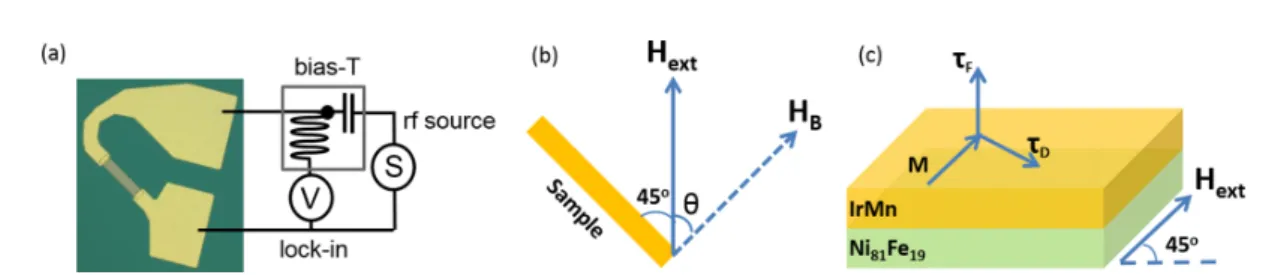
FIG. 1. (a) Schematic representation of the spin-torque ferromagnetic resonance experimental setup. (b) Relative orientations between exchange bias and external field during spin-torque ferromagnetic resonance measurement. (c) Illustrative picture of a Ni81Fe19/IrMn showing
the spin-transfer torques τFand τD, magnetization M, and external field Hext.
SiO2substrate using magnetron sputtering, photolithography,
and ion milling [28]. Ni81Fe19and IrMn were kept at 6 and
8 nm in thickness, respectively. Subsequently, contact pads [Ti (3 nm)/Au (150 nm)] were deposited on the samples for electri-cal measurements [see Fig.1(a)]. In order to establish exchange bias, the patterned antiferromagnet/ferromagnet samples were annealed at 250 °C in vacuum and subsequently cooled down to room temperature in the presence of 600-Oe magnetic field. Note that all the devices with different relative orientations were fabricated on the same chip and annealed simultaneously. Spin-torque ferromagnetic resonance measurements were performed for all the samples with various relative orienta-tions between exchange bias and external field [Fig.1(b)]. A schematic of the measurement setup is illustrated in Fig.1(a). An oscillating charge current was driven through rf probes in contact with the contact pads. This oscillating charge current generates a transverse spin current, which exerts a torque on the magnetization of Ni81Fe19. The rf current flowing
through the Ni81Fe19 layer mixes with the time-dependent
resistivity of the Ni81Fe19due to anisotropic magnetoresistance
in response to the oscillating magnetization, which results in a rectified dc voltage that was measured as a function of applied magnetic field. During the measurements, a 10-mW fixed microwave current was applied with frequencies varied from 8 to 15 GHz and the external magnetic field was kept constant at 45◦ with respect to the rf current direction [Fig. 1(c)].
Note that all the measurements have been performed at room temperature, which is below the blocking temperature of Ni81Fe19/IrMn [29].
Figure2(a)shows typical measured spin-torque ferromag-netic resonance signals for a Ni81Fe19/IrMn sample at
frequen-cies of 8, 10, 12, and 14 GHz and θ = 0◦. As the microwave
frequency increases, the resonance field shifts towards higher fields, which is in agreement with the Kittel model [30], and the magnitude of measured dc voltage (V ) decreases. Here, the measured dc voltages are sums of symmetric and antisymmetric Lorentzian components, which can be attributed to dampinglike and fieldlike torques, respectively. Figure2(b)
shows a spin-torque ferromagnetic resonance spectrum, which was measured at 8 GHz and decomposed into its symmetric (Vs) and antisymmetric (Va) Lorentzian voltage contributions.
In order to illustrate the angular dependence of exchange bias on spin-orbit torques, we examine the ratio of symmetric to antisymmetric voltage contributions, as well as associated effective spin Hall angles [31] for both negative and positive external fields. We extracted the symmetric and antisymmetric voltage contributions by fitting the spin-torque ferromagnetic resonance curves [20]: V= ! Vs "H2 "H2+ (Hext− Hres)2+ Va "H(Hext− Hres) "H2+ (Hext− Hres)2 " , (1) where "H is the resonance linewidth, Hextis the applied field,
and Hres is the resonance field for ferromagnetic resonance
at a given frequency. The effective spin Hall angles can be quantified via the ratio of symmetric and antisymmetric voltage
FIG. 2. (a) Measured spin-torque ferromagnetic resonance signals at 8, 10, 12, and 14 GHz with the angle θ = 0◦between the applied field
and the exchange bias direction. (b) Single spin-torque ferromagnetic resonance spectrum measured at 8 GHz. The red solid line represents the fit to the Lorentzian function. The green dashed and blue dash-dotted lines represent symmetric and antisymmetric voltage components, respectively.
FIG. 3. (a) Spin-torque ferromagnetic resonance spectra obtained at 12 GHz illustrate the resonance field shift due to exchange (for θ = 0◦).
Blue and red curves depict positive and negative field sweeps, respectively. (b) Magnetic hysteresis loop for Ni81Fe19(6) thin film (red circles)
and Ni81Fe19(6)/IrMn(8) bilayer (black squares). (c) Measured in-plane exchange bias field HB, which represents the relative orientation of
exchange bias anisotropy with respect to the measurement field Hext.
contributions [20]: !effSH= Vs Va eµ0MstAFtFM ¯h ! 1 +4πMs Hext "1/2 , (2)
where µ0 is the permeability in vacuum, tAF and tFM are
the thicknesses of the ferromagnetic and antiferromagnetic layers, respectively, and Ms is the saturation magnetization
of Ni81Fe19, which can be extracted by fitting the resonance
frequency as a function of Hresby the Kittel equation [30]:
fres=
γ
2π[(Hres+ HB)(Hres+ HB+ 4πMs)]1/2, (3)
where HBis the effective exchange bias field.
In exchange biased ferromagnetic/antiferromagnetic bilay-ers, the exchange anisotropy gives rise to a resonance shift and enhanced linewidth broadening compared to unbiased films [32]. Patterning samples in four different directions with respect to the unidirectional exchange bias anisotropy, i.e., θ = 0, 45, 90, and 135◦, enables us to control the shift
in resonance field during measurements [33,34]. Figure3(a)
shows the measured dc voltage as a function of field at 12 GHz for θ = 0. When the measurement field and exchange bias field are parallel (perpendicular) to each other, we measured the maximum (minimum) resonance field shift of 60 Oe. This exchange bias shift can also be seen in the magnetization versus
field curve for the Ni81Fe19/IrMn bilayer [see Fig.3(b)]. The
summary of electrically measured exchange bias fields for all angles (θ = 0, 45, 90, and 180◦) is shown in Fig.3(c).
We also measure effective damping ("a) due to the ex-change bias, which can be extracted from the frequency dependence of the linewidth broadening [35] ("H ) [Fig.4(a)]. Almost identical "a values were observed for all directions [see Fig.4(b)]. If we consider that at least part of the effective damping is related to spin pumping into the adjacent IrMn, then this suggests that the efficiency of spin current transmission at the interface is approximately identical for all directions, i.e., independent from the exchange bias direction. Furthermore, the additional effective damping for our Ni81Fe19/IrMn sample
is larger than the measured value in the previous study [10], where exchange coupling at the interface is eliminated by inserting a thin Cu layer. This can be attributed to magnetic losses in the antiferromagnetic spin lattice, which is also directly exchange coupled to the ferromagnetic magnetiza-tion in the Ni81Fe19 and therefore can provide additional
damping.
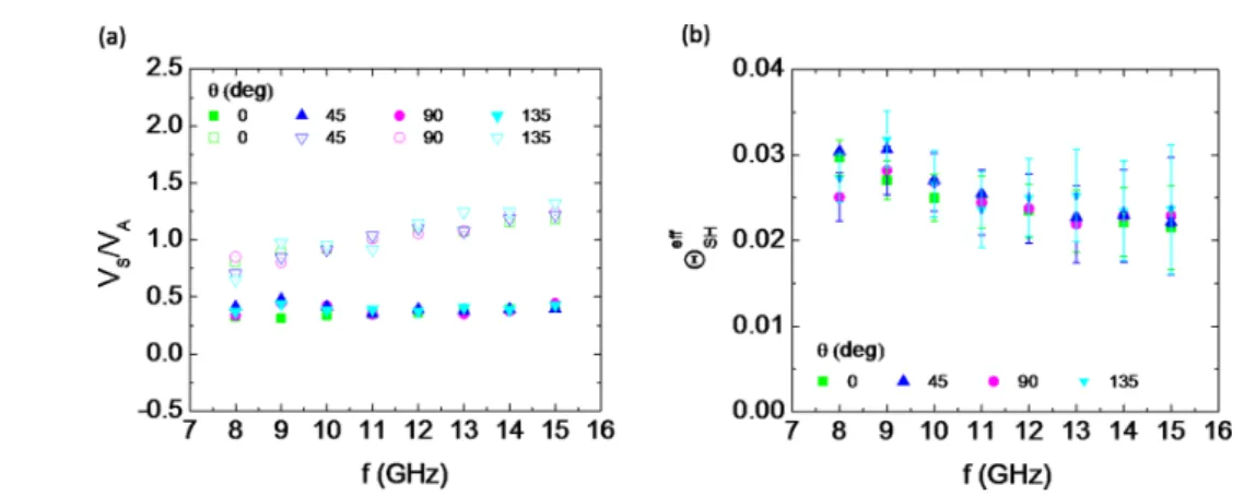
Figure5(a)shows the ratio of symmetric and antisymmetric voltages for frequencies ranging from 8 to 15 GHz. No angular dependence of Vs/Vawas observed, which is consistent with
the effective damping data. These findings suggest that both
FIG. 4. (a) Frequency dependence of the linewidth broadening "H , for varying θ (for positive field sweeping). (b) Effective damping "α as a function of θ for positive and negative fields.
HILAL SAGLAM et al. PHYSICAL REVIEW B 98, 094407 (2018)
FIG. 5. (a) Ratio of symmetric voltage to antisymmetric voltage for varying frequencies from 8 to 15 GHz. Open and closed circles represent negative and positive field sweeping, respectively. (b) Effective spin Hall angles !eff
SHas a function of frequency for different θ.
dampinglike (given by Vs) and Oersted-fieldlike torques (given
by Va) are independent of the local spin structure at the
Ni81Fe19/IrMn interface. However, we observed that Vs/Va
values for positive and negative fields differ slightly. A possible explanation for this difference could be a resonant heating of the samples. Together with the asymmetric structure of the sample layout [see Fig.1(a)], this may result in a lateral tem-perature difference. Ultimately, this difference may generate additional Seebeck voltage across the sample, which is due to the fact that the resonant heating should have a symmetric Lorentzian line shape.
Ignoring this offset, the averaged effective spin Hall angles for positive and negative fields for varying microwave exci-tation frequencies from 8 to 15 GHz are shown in Fig.5(b). The effective spin Hall angles for different relative orienta-tions between exchange anisotropy and external field show very small variation, and we estimate !eff
SH= (2.8 ± 0.3)%.
We observed slightly smaller spin Hall angles compared to previous measurements [10] in the presence of a Cu interlayer between IrMn and Ni81Fe19. Furthermore, measurements with
thicker IrMn (15 nm) show qualitatively the same behavior, i.e., we observe no dependence of spin Hall angles on relative orientations between exchange bias and current flow, and the effective damping is almost identical for all directions. Our observations are inconsistent with previous spin-orbit ferromagnetic measurement experiments on the NiFe/IrMn system, where a large enhancement of dampinglike torques
was measured arising from the antiferromagnetic order at the interface [18].
We conclude that there is no dependence of the effective spin Hall angles on the relative orientation of the in-plane exchange bias with respect to current flow and thus the polarization direction of the concomitant spin currents and accumulations. However, there are still strong spin-orbit torques even when the antiferromagnet is directly exchange coupled to the ferromag-net. We also observe a similar trend in ferromagnetic resonance data, where the angular dependence of effective damping is almost identical for all directions, which may suggest that the spin current transmission through the Ni81Fe19/IrMn interface
is not affected by the local magnetic structure.
The work at Argonne National Laboratory including exper-imental design, magneto-optic measurements, data analysis, and manuscript preparation was supported by the U.S. De-partment of Energy (DOE), Office of Science, Basic Energy Sciences, Materials Science and Engineering Division under Contract No. DE-AC02-06CH11357. Work at the Université de Loraine including sample preparation and transport measure-ments was supported by the French Projet d’Investissement d’Avenir project “Lorraine Université d’Excellence,” Project No. ANR-15-IDEX-04-LUE. Lithographic patterning was car-ried out at the Micro and Nanotechnology Platform of Lorraine. W.Z. acknowledges support from the DOE Visiting Faculty Program.
[1] A. Hoffmann and S. D. Bader,Phys. Rev. Appl. 4, 047001
(2015).
[2] M. B. Jungfleisch, W. Zhang, and A. Hoffmann,Phys. Lett. A. 382,865(2018).
[3] V. Baltz, A. Manchon, M. Tsoi, T. Moriyama, and Y. Tserkovnyak,Rev. Mod. Phys. 90,015005(2018).
[4] J. Zelezny, H. Gao, K. Vyborny, J. Zemen, J. Masek, A. Manchon, J. Wunderlich, J. Sinova, and T. Jungwirth,Phys. Rev. Lett. 113,157201(2014).
[5] B. G. Park, J. Wunderlich, X. Marti, V. Holy, Y. Kurosaki, M. Yamada, H. Yamamoto, A. Nishide, J. Hayakawa, H. Takahashi, A. B. Shick, and T. Jungwirth,Nat. Mater. 10,347(2011).
[6] X. Marti, B. G. Park, J. Wunderlich, H. Reichlova, Y. Kurosaki, M. Yamada, H. Yamamoto, A. Nishide, J. Hayakawa, H. Takahashi, and T. Jungwirth, Phys. Rev. Lett. 108, 017201
(2012).
[7] S. M. Rezende, R. L. Rodríguez-Suárez, and A. Azevedo,
Phys. Rev. B 93,014425(2016).
[8] S. M. Wu, W. Zhang, A. KC, P. Borisov, J. E. Pearson, J. S. Jiang, D. Lederman, A. Hoffmann, and A. Bhattacharya,
Phys. Rev. Lett. 116,097204(2016).
[9] W. Zhang, M. B. Jungfleisch, W. Jiang, J. E. Pearson, A. Hoffmann, F. Freimuth, and Y. Mokrousov,Phys. Rev. Lett. 113,
196602(2014). 094407-4
113,097202(2014).
[13] L. Frangou, S. Oyarzún, S. Auffret, L. Vila, S. Gambarelli, and V. Baltz,Phys. Rev. Lett. 116,077203(2016).
[14] P. Wadley, B. Howells, J. Železný, C. Andrews, V. Hills, R. P. Campion, V. Novák, K. Olejník, F. Maccherozzi, S. S. Dhesi, S. Y. Martin, T. Wagner, J. Wunderlich, F. Freimuth, Y. Mokrousov, J. Kuneš, J. S. Chauhan, M. J. Grzybowski, A. W. Rushforth, K. W. Edmonds, B. L. Gallagher, and T. Jungwirth,
Science 351,587(2016).
[15] M. I. D’yakonov and V. I. Perel, Sov. Phys. JETP Lett. 13, 467 (1971).
[16] J. E. Hirsch,Phys. Rev. Lett. 83,1834(1999). [17] S. Zhang,Phys. Rev. Lett. 85,393(2000).
[18] V. Tshitoyan, C. Ciccarelli, A. P. Mihai, M. Ali, A. C. Irvine, T. A. Moore, T. Jungwirth, and A. J. Ferguson,Phys. Rev. B 92,
214406(2015).
[19] A. Hoffmann,IEEE Trans. Magn. 49,5172(2013).
[20] L. Liu, T. Moriyama, D. C. Ralph, and R. A. Buhrman,
Phys. Rev. Lett. 106,036601(2011).
[21] W. Zhang, W. Han, S. Yang, Y. Sun, Y. Zhang, B. Yan, and S. S. P. Parkin,Sci. Adv. 2,e1600759(2016).
Schuller,Phys. Rev. Lett. 84,3466(2000).
[26] J. Nogués and I. K. Schuller,J. Magn. Magn. Mater. 192,203
(1999).
[27] A. H. MacDonald and M. Tsoi,Philos. Trans. R. Soc. A 369,
3098(2011).
[28] G. Malinowski, M. Hehn, S. Robert, O. Lenoble, A. Schuhl, and P. Panissod,Phys. Rev. B 68,184404(2003).
[29] V. Baltz, J. Sort, S. Landis, B. Rodmacq, and B. Dieny,
Phys. Rev. Lett. 94,117201(2005). [30] C. Kittel,Phys. Rev. 73,155(1948).
[31] J.-C. Rojas-Sánchez, N. Reyren, P. Laczkowski, W. Savero, J.-P. Attané, C. Deranlot, M. Jamet, J.-M. George, L. Vila, and H. Jaffrès,Phys. Rev. Lett. 112,106602(2014).
[32] M. Rubinstein, P. Lubitz, and S. Cheng,J. Magn. Magn. Mater. 195,299(1999).
[33] A. Hoffmann, M. Grimsditch, J. E. Pearson, J. Nogues, W. A. A. Macedo, and I. K. Schuller,Phys. Rev. B 67,220406(R)
(2003).
[34] S. H. Chung, A. Hoffmann, and M. Grimsditch,Phys. Rev. B 71,214430(2005).