HAL Id: ensl-00379154
https://hal-ens-lyon.archives-ouvertes.fr/ensl-00379154v2
Submitted on 28 Apr 2009
HAL is a multi-disciplinary open access
archive for the deposit and dissemination of
sci-entific research documents, whether they are
pub-lished or not. The documents may come from
teaching and research institutions in France or
abroad, or from public or private research centers.
L’archive ouverte pluridisciplinaire HAL, est
destinée au dépôt et à la diffusion de documents
scientifiques de niveau recherche, publiés ou non,
émanant des établissements d’enseignement et de
recherche français ou étrangers, des laboratoires
publics ou privés.
Generating high-performance custom floating-point
pipelines
Florent de Dinechin, Cristian Klein, Bogdan Pasca
To cite this version:
Florent de Dinechin, Cristian Klein, Bogdan Pasca. Generating high-performance custom
floating-point pipelines. Field Programmable Logic and Applications, Aug 2009, Prague, Czech Republic.
�ensl-00379154v2�
GENERATING HIGH-PERFORMANCE CUSTOM FLOATING-POINT PIPELINES
LIP RESEARCH REPORT 2009-16
Florent de Dinechin, Cristian Klein and Bogdan Pasca
LIP (CNRS/INRIA/ENS-Lyon/UCBL), Universit´e de Lyon
´
Ecole Normale Sup´erieure de Lyon
46 all´ee d’Italie, 69364 Lyon cedex
email: {Florent.de.Dinechin, Cristian.Klein, Bogdan.Pasca}@ens-lyon.fr
ABSTRACT
Custom operators, working at custom precisions, are a key ingredient to fully exploit the FPGA flexibility advantage for high-performance computing. Unfortunately, such op-erators are costly to design, and application designers tend to rely on less efficient off-the-shelf operators. To address this issue, an open-source architecture generator framework is introduced. Its salient features are an easy learning curve from VHDL, the ability to embedd arbitrary synthe-sisable VHDL code, portability to mainstream FPGA targets from Xilinx and Altera, automatic management of complex pipelines with support for frequency-directed pipeline, au-tomatic test-bench generation. This generator is presented around the simple example of a collision detector, which it significantly improves in accuracy, DSP count, logic usage, frequency and latency with respect to an implementation us-ing standard floatus-ing-point operators.
1. INTRODUCTION 1.1. Flexible operators for FPGAs
FPGA-based coprocessors are available from a variety of vendors and may be used for accelerating intensive compu-tations, including floating-point (FP) ones. On matrix multi-plication, their floating-point performance barely surpasses that of a contemporary processor [1], using tens of operators on the FPGA to compensate their much slower frequency. Besides, FPGAs are in competitions with GPUs here. There is much more acceleration potential in operations for which processors or GPU have no dedicated hardware, for instance double-precision elementary functions [2] or special func-tions used in the generation of floating-point random num-bers [3]. Besides, operators can also be specialized in FP-GAs. For example, a squarer requires less logic than a
mul-This work was partly supported by the XtremeData university pro-gramme, the ANR EVAFlo project and the Egide Brˆancus¸i programme 14914RL.
tiplier; A floating-point multiplication by the constant 2.0 boils down to adding one to the exponent (a 12-bit addi-tion for double-precision), and need not use a full-blown FP multiplier as it does in a processor. Indeed it is possible to build an optimized architecture for any multiplication by a constant [4]. Finally, and building upon the previous op-timizations, operators can be fused on an FPGA [5]. The running example illustrating this article is such a fused op-erator, a collision detection predicate, testing if the norm of a 3D vector is larger than some threshold.
The recipe for implementing such operators is to respect their floating-point interface, but perform most internal com-putations in fixed point for which FPGAs are highly opti-mized. This recipe is also used in block-floating floating-point approaches [6] and in recent experimental C-to-FPGA datapath synthesis tools [5].
There are many more opportunities for floating-point on FPGAs [7]. The goal of the FloPoCo project1 is
to study and develop such FPGA-specific Floating-Point Cores. FloPoCo is both a software framework and a gen-erator of arithmetic cores using this framework. It currently offers about 20 operators, from simple ones such as shifters or integer adders to very complex ones such as floating-point exp and log. Some of the original operators have been de-scribed elsewhere [8, 2, 4, 9], and this article presents the framework itself. FloPoCo is distributed under the LGPL, and interested readers are welcome to try it, use it and im-prove it.
1.2. The arithmetic context
Our definition of an arithmetic operator is much broader than the usual +, −, × and /. In this work, an arithmetic operator is the implementation of any useful mathematical function, be it ln(− ln(x)) [3] or √ x
x2+y2+z2.
Although very general, this mathematical definition has
many important consequences when designing an operator. To start with, being the implementation of a function, an op-erator usually involves no feedback loop or state machine2.
This restriction enables a simple framework for quickly de-veloping high-performance pipelined operators out of com-binatorial ones. This is a major contribution of this work and will be exposed in Section 3.2.
When an operator is defined as the implementation of a mathematical function, the error analysis and design-space exploration may be much more accurate than when it is the implementation of a C program [5]. Finally, the mathemat-ical function also defines a reference for testing, as will be detailed in Section 4.
1.3. From libraries to generators
Although early FP operators were proposed as VHDL or Verilog libraries, the current trend is to shift to generators of operators (see [10] and references therein). A generator is a program that inputs user specifications, performs any rele-vant architectural exploration and construction (sometimes down to pre-placement), and outputs the architecture in a synthesizable format. Most FPGA designers are familiar with the Xilinx core generator tool, which to our knowledge3
pioneered this approach, or its Altera MegaWizard counter-part. A generator may simply wrap a library – and for the simplest operators there is no need for more – but it can also be much more powerful.
Firstly, the size of a library including multipliers by all the possible constants would be infinite, but the generation of an architecture for such a multiplier may be automated as a program that inputs the constant [4]. The same holds for arbitrary function generators [8].
Secondly, generators allow for greater parameterization and flexibility. Whether the best operator is a slow and small one or a faster but larger one depends on the context. FPGAs also allow flexibility in precision: arithmetic cores should be parameterized by the bit-widths of their inputs and out-puts. We are also concerned about optimizing for different hardware targets, with different LUT structure, memory and DSP features, etc. The more flexible a generator, the more future-proof.
Lastly, generators may perform arbitrarily complex design-space exploration, automated error analysis, and op-timization [8, 2].
1.4. Design choices for FloPoCo
A generator could in principle be written in VHDL or Ver-ilog, but these languages are not ideally suited for that. In particular, complex programs turn out to be inefficient and
2The only current exception is an accumulator [9] which is indeed
de-signed with a minimal, well isolated feedback loop.
3We would welcome any feedback on early architecture generators
difficult to debug using the simulation/synthesis paradigm of hardware description languages. Still, an architecture gen-erator needs a back-end to actually implement the resulting circuit. The most elegant solution is to write a generator as an overlay on a software-based HDL such as SystemC, JBits, HandelC or JHDL (among many others). The advan-tages are a preexisting abstraction of a circuit, and simple integration with a one-step compilation process. The incon-venience is that most of these languages are still relatively confidential and restricted in the FPGAs they support. Even SystemC synthesizers are far from being commonplace yet. Basing our generator on a vendor generator would be an op-tion, but would mean restricting it to one FPGA family.
The proposed generator took a less elegant, but more universal route. The generator is written in a mainstream programming language (we chose C++, mostly for compati-bility with other previous work), and it outputs operators in a mainstream HDL (we chose standard synthesisable VHDL). We thus get a portable generator, and the generated oper-ators can be integrated into most projects, simulated using mainstream simulators, and synthesized for any FPGA us-ing the vendor back-end tools. Section 3.3 will discuss how they can nevertheless be optimized to a given FPGA target.
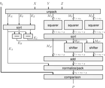
2. A SIMPLE MOTIVATING EXAMPLE This framework has been used to write and pipeline very large components, such as the floating-point logarithm de-scribed in [2]. We choose to discuss here a simpler, but still representative example: the implementation of a col-lision detection predicate, testing if the norm of a 3D vector is larger than some threshold. Let x, y, z and r2 be four floating-point inputs, and let us design an operator testing wether x2+ y2+ z2< r2.
A first option is to assemble three FP multipliers and two FP adders. The final comparison can be performed by an integer subtraction on the concatenation of the exponent and the mantissa – a well-known property of IEEE-754 FP formats is that positive FP numbers are ordered in the lexi-cographic order of their binary representation.
Let us now design a specific operator for this compu-tation. There are many optimization opportunities with re-spect to the previous solution.
• As already mentionned, the squarers should be sim-pler than multipliers. They will in particular use less DSP blocks.
• We only add positive numbers. In an off-the-shelf floating-point adder, roughly half the logic is dedi-cated to effective subtraction, and can be saved here. An optimizing synthesizer would probably perform this optimization4, but it will not, for instance, reduce
1 + wF 1 + wF 1 + wF 2 + wF+ g 2 + wF+ g 2 + wF+ g 2 + wF+ g 2 + wF+ g 4 + wF+ g wE+ wF+ g 2 + wF+ g EA EC EB MB 2 MC2 P R2 X Y Z MX EZ EY EX MY MZ MA2 shifter sort
sort squarer squarer squarer
shifter add
comparison normalize/pack unpack
Fig. 1. Overview of the custom floating-point collision op-erator.
the pipeline depth accordingly.
• The significands of x2, y2 and z2 are aligned
be-fore addition. This may be done in parallel, reduc-ing pipeline depth and register usage with respect to an implementation using two floating-point adders in sequence.
• A lot of logic is dedicated to rounding intermediate re-sults, and can be saved by considering the compound operator as an atomic one [5]. We obtain an operator that is not only simpler, but also more accurate. Actually, it is common for a fused operator to be more accurate than the combination of FP ones. Here, the idea is to evaluate x2+y2+z2with 1-ulp (unit in the last place) ac-curacy before the comparison, where a combination of stan-dard operators leads to a worst-case error larger than two ulps. More subtly, with an operator built by assembling two FP adders, there are some rare cases when the value of the predicate will change when one exchanges x and z. This is due to the two consecutive roundings. We will be able to design an operator which doesn’t have such asymmetries. It is even possible to design an exact predicate, that doesn’t perform any rounding before the comparison – it probably doesn’t make much sense unless x, y and z are computed exactly themselves.
The chosen architecture is depicted on Figure 1. For more details the interested reader is invited to have a look at
theCollisionoperator in the FloPoCo distribution. This
architecture computes the three squares, truncates them to wF + g bits, then aligns them to the largest one and adds
them. Worst-case error analysis shows that there are 5 trun-cation errors in this computation (the three products, and bits
Fig. 2. FloPoCo class hierarchy (very simplified overview)
discarded by the two shifters). The number of guard bits g is therefore set to g = dlog2(5)e = 3 so that the accumu-lated error is always smaller than the unit in the last place of r2. Comparison is performed as integer subtraction as previously, except that r2 is extended to wF+ g bits.
Table 1 shows quantitatively the savings brought by this approach. All the metrics are significantly improved (from 25 to 89 %) by operator specialization and fusion. The (8,23) FP version implemented using LogiCore illustrates that FloPoCo provides FP operators of comparable quality.
Another meaningful result is design time. Assembling FP operators took two hours, for a pipeline that is fully pa-rameterized by wE, wF and target frequency. Assembling
the Logicore version took even less time, but one doesn’t obtain a parameterized design. The optimized version took two days to write, including the testbench. It may seem a lot of design time, but most of the work concerns the sum-of-square operator, which will also be used for future coarser-grain operators such aspx2+ y2+ z2or √ x
x2+y2+z2. And again, this design is fully parameterized, pipelined, and au-tomatically optimized for a given frequency.
Let us now present in more details the framework used to obtain these results.
3. THE FRAMEWORK
In the following, we assume basic knowledge of object-oriented concepts with the C++ terminology5. Figure 2
pro-vides a very simplified overview of the FloPoCo class hier-archy.
3.1. Operators
The core class isOperator. From the circuit point of view,
anOperatorcorresponds to a VHDL entity, but again, with
restrictions and extensions specific to the arithmetic context. All the operators extend this class, includingCollision,
5For an introduction, see http://en.wikipedia.org/wiki/
Slow version Fast version Precision (wE, wF) area perf area perf
(8,23) LogiCore FP 1282 slices, 20 DSP 43 cycles @ 353 MHz (8,23) FP 940 slices, 12 DSP 20 cycles @ 210 MHz 1188 slices, 12 DSP 29 cycles @ 289 MHz (8,23) custom 456 slices, 9 DSP 10 cycles @ 319 MHz 453 slices, 9 DSP 11 cycles @ 368 MHz (9, 32) FP 1268 slices, 12 DSP 20 cycles @ 171 MHz 1874 slices, 12 DSP 37 cycles @ 302 MHz (9, 32) custom 629 slices, 9 DSP 10 cycles @ 368 MHz 640 slices, 9 DSP 13 cycles @ 368 MHz (11, 52) FP 2868 slices, 27 DSP 20 cycles @ 106 MHz 4480 slices, 27 DSP 46 cycles @ 276 MHz (11, 52) custom 1532 slices, 18 DSP 10 cycles @ 237 MHz 1845 slices, 18 DSP 16 cycles @ 362 MHz Table 1. Some post-synthesis results for the Collision operator (on Virtex-4 xc4vlx15-12-sf363 using ISE 10.1 or 9.1, whichever gave the best results). Note that the custom version is also the most accurate. The FloPoCo command-line used to obtain these results is flopoco -frequency= f Collision wEwF o where f is 200 for the slow version and 400 for
the fast version, and o is 0 for the FP version and 1 for the optimized version.
but also some of its sub-components (shifters, squarers and adders) seen on Figure 1.
The main method of ofOperatorisoutputVHDL(), which prints out the VHDL code of an operator. To imple-ment this virtual method for an operator, one may simply embed some existing VHDL code in the C++.
However, the standard way of using the framework is to rely on the default implementation ofoutputVHDL() pro-vided by theOperatorclass. This default method takes the VHDL code of the operator architecture from the vhdl stream, an attribute ofOperator. Thus, one designs the architecture by having the constructor outputting arbitrary VHDL code to vhdl. In addition, signals may be wrapped in methods fromOperator. A first method isdeclare(), that handles signal declaration. Consider the following code that computes the difference of two exponents of size wE,
in order to determine inXltYwhich is smaller.
vhdl << declare("DEXY", wE+1)
<< " <= (’0’ & EX) - (’0’ & EY);" << endl; vhdl << declare("XltY")
<< " <= DEXY("<< wE<<");" << endl;
Here thedeclare()method adds the signal to the sig-nalListof the operator (so thatoutputVHDL()will declare it in the VHDL), then simply returns its first argument. Thus, called with wE = 8, the code above simply puts in the vhdl
stream the string:
DEXY <= (’0’ & EX) - (’0’ & EY);
XltY <= DEXY(8);
So far we have mostly obfuscated the VHDL with C++ constructs. Let us see how this enables easy pipelining.
3.2. Automatic pipeline management
We now consider the end of thenormalise/packbox of Fig-ure 1, which reassembles the result from the exponent dat-apath and the fraction datdat-apath into a single bit vector. The
exponent datapath is in general shorter (computed in less cycles), so there is a need for synchronisation. The cycle difference depends on the pipeline depths of theshifterand
addcomponents, which in turn depends on operand sizes, target hardware, and target frequency. Building a working pipeline for a given set of parameters is conceptually sim-ple: simply insert registers to delay the result of the shortest datapath, so as to synchronise it with the result of the longest one. FloPoCo allows to express exactly that in a generic way. Consider the following code excerpt:
(...)
// at some cycle
vhdl << declare("finalExp", wE+1) << " <= " ... (...)
// at some other cycle
vhdl << declare("finalFraction", wF+g) << " <= " ... (...)
// enter next cycle nextCycle();
vhdl << declare("finalSoP", wE+wF+g) << " <= " << use("finalExp") << "(wE-1 downto 0)" << " & " << use("finalFraction") << "; ";
During the construction of the VHDL in the vhdl stream,
an Operatormaintains a currentCycle attribute, initially
equal to zero. The main function of nextCycle()is to increment currentCycle.
Every signal declared throughaddInputor declare
has a cycle attribute, which represents the cycle at which this signal is computed. It is 0 for the inputs. For signals declared throughdeclare(), it is set to currentCycle at the
timedeclare()is invoked.
Every signal also possesses an attribute lifeSpan which indicates how many cycles it will need to be delayed. This attribute is initialized to 0, then possibly increased byuse()
as we will see below. When the lifeSpan of a signalX is greater than zero,outputVHDL()will create lifeSpan new signals, namedX d1, X d2 and so on, and insert registers between them. In other words,X d2will hold the value ofX
Wrapping a signal in use() has the following effect. First, use("X")will compare currentCycle and the cycle declared forX, which we noteX.cycle.
• If they are equal, use("X")will simply return the string"X".
• If currentCycle <X.cycle,use("X")will emit an er-ror message reporting thatXis being used before the cycle at which it was defined.
• If currentCycle >X.cycle,use("X")will delay sig-nalXby n = currentCycle − X.cycle cycles. Tech-nically, if n = 5 for instance,use("X")just returns
"X d5". It also updatesX.lifeSpanto be at least equal to 5.
Operator defines several other functions to
manage currentCycle, such as setCycle(int n),
setCycleFromSignal(string s) which sets the
currentCycle to the cycle of the signal whose name is given as an argument (going back if needed), and
syncCycleFromSignal(string s) which may only
advance currentCycle. The latter allows to synchronise several signals by setting currentCycle to the max of their cycle.
It should be noted that this scheme still allows for arbi-trary synthesizable VHDL – only the signal names have to be wrapped byuse(),declare(), etc. Also, this scheme gracefully degrades to a combinatorial operator – in this
mode declare() always declares one single signal and
use()always returns its argument unmodified.
Code written under this scheme will automatically adapt to random insertions and suppressions of synchronization barriers. Typically, if one is unhappy with the performance, one may decide to break the critical path by inserting a syn-chronisation barrier in it. This may be as simple as inserting a singlenextCycle()in the code. FloPoCo takes care of the rest.
Finally, it is also possible to wrap in conditional state-ments some of thenextCycle()calls, so that the pipeline adapts to the frequency, the operator generic parameters, etc. For instance, theIntAdderor Shiftersclasses of FloPoCo produce operators whose pipeline depth depends on the target frequency. By using these pre-existing sub-components, ourCollisionoperator behaves the same, as Table 1 shows.
Space limitation prevents presenting in details how sub-components are managed in FloPoCo. In short, one has to create an object instance for the subcomponent, then there is ainPortMap()method that is conceptually simi-lar touse(), anoutPortMap()method conceptually simi-lar todeclare(), and aninstance()method that returns the VHDL of the instance, and performs the bookkeeping required foroutputVHDL() to declare the corresponding
component. We invite the interested reader to have a look at
Collision.cpp.
3.3. Targets
The Target class abstracts the features of actual FPGA
chips. Classes representing real FPGA chips extend this class (we currently have classes for two very different FP-GAs, XilinxVirtex4and AlteraStratixII). The idea is to declare abstract methods in Target, which are imple-mented in its subclasses, so that the same generator code fits all the targets. Of course, it is also possible to have a con-ditional statement that runs completely different code de-pending on the target – this will be the case for instance for theIntMultiplierclass that builds large multipliers, be-cause DSP capabilities are too variable from one target to the other. ATargetis given as argument to the constructor of any operator.
The methods provided by theTarget class can be se-mantically split into two categories:
• Architecture-related methods provide information about the architecture of the FPGA and are used in ar-chitectural exploration. For instance,lutInputs()
returns the number of inputs of the FPGA’s LUTs. • Delay-related methods provide approximative
in-formations about computation time. For example,
adderDelay(int n) returns the delay of an n-bit
addition. These methods are used for frequency-directed pipelining (here for IntAdder). Some of these methods have an architecture-related dual, for examplesuggestAdderSize(double delay)
that returns the size of an adder that will have the re-quired delay.
The difficulty here is to find the right abstraction level
forTarget. On one hand, we do not hope to provide an
exhaustive and detailed description of all the existing – and future – FPGAs. On the other hand, we do not need to: Ven-dor tools are very good at fitting a design to a given target, and we should rely on them. The complexity of exploiting the details of the target should be left to the back-end tools.
Targetis still expected to evolve a lot. Other methods will be added when needed, for instance to model the inter-nal memory resources. Also, area estimation methods will assist the design-space exploration of future operators. And of course, the question of target abstraction will remain an open one forever, as new FPGA features keep appearing and new operators present new problems.
4. TESTBENCH GENERATION
The undelying mathematical nature of an arithmetic opera-tor can be usefully exploited to make testbench generation
easy. For instance, the output from a floating-point opera-tor may be defined as a mathematical function of the inputs (addition or exponential) composed with one of the rounding functions defined in the well established IEEE-754 standard [11]. Defining expected outputs this way is not only simpler than mimicking the architecture, it also minimizes the pos-sibility of making the same mistake in both the operator and its test bench. In FloPoCo, one has to overload the Opera-tor virtual methodemulate(). Thanks to the bit-accurate MPFR library [12], this typically takes about ten lines.
Overloading emulate()is enough for FloPoCo to be able to create a generic test bench using random inputs. However, function analysis also allows for better, more operator-specific test-case generation. Let us just take two examples.
• A double-precision exponential returns +∞ for all inputs larger than 710 and returns 0 for all inputs smaller than −746. In other terms, the most inter-esting test domain for this function is when the input exponent is between −10 and 10, a fraction of the full double-precision exponent domain (−1024 to 1023). Generating random 64-bit integers and using them as floating-point inputs would mean testing mostly the overflow/underflow logic, which is a tiny part of the operator.
• In a floating-point adder, if the difference between the exponents of the two operands is large, the adder will simply return the biggest of the two, and again this is the most probable situation when taking two random operands. Here it is better to generate random cases where the two operands have close exponents. Such cases are managed by overloading the Oper-ator method buildRandomTestCases(). Finally,
buildStandardTestCases()allows to test corner cases
which random testing has little chance to find.
5. CONCLUSION
This article introduced an open-source software framework for generating high-quality, highly parameterized, pipelined and flexible operators for FPGAs. This framework evolved (and still evolves) in a deliberately bottom-up and practical way focussed on the needs of arithmetic cores. It is based on embedding VHDL code in a simple C++ framework. Thus it provides the full power of the VHDL language. It adds to it facilities for automatic pipeline construction and synchronization, target-based and frequency-based optimi-sation, and test bench generation.
In its current state, this generator is already an invaluable booster for the core focus of our research, which is to de-velop new arithmetic operators. In the future, a wider range
of design objectives may be added: optimizing for power, for a given pipeline depth, for memory, etc. In addition, we will refine and extend the FPGA model as new needs appear, for instance to model the internal memory resources.
We have also shown how the automatic pipeline frame-work can be used to build larger computation pipelines composed of many operators, which automatically adapt to changes in precision or target frequency. What is now needed is a more user-friendly interface.
6. REFERENCES
[1] D. Strenski, J. Simkins, R. Walke, and R. Wittig, “Revaluat-ing FPGAs for 64-bit float“Revaluat-ing-point calculations,” HPC wire, May 2008.
[2] J. Detrey, F. de Dinechin, and X. Pujol, “Return of the hard-ware floating-point elementary function,” in 18th Symposium on Computer Arithmetic. IEEE, 2007, pp. 161–168. [3] N. Woods and T. VanCourt, “FPGA acceleration of
quasi-Monte Carlo in finance,” in Field Programmable Logic and Applications, 2008, pp. 335–340.
[4] N. Brisebarre, F. de Dinechin, and J.-M. Muller, “Inte-ger and floating-point constant multipliers for FPGAs,” in Application-specific Systems, Architectures and Processors. IEEE, 2008, pp. 239–244.
[5] M. Langhammer, “Floating point datapath synthesis for fp-gas,” in Field Programmable Logic and Applications, 2008, pp. 355–360.
[6] R. Andraka, “Hybrid floating point technique yields 1.2 gi-gasample per second 32 to 2048 point floating point FFT in a single FPGA,” in High Performance Embedded Computing Workshop, 2006.
[7] F. de Dinechin, J. Detrey, I. Trestian, O. Cret¸, and R. Tudo-ran, “When FPGAs are better at floating-point than micro-processors,” ´Ecole Normale Sup´erieure de Lyon, Tech. Rep. ensl-00174627, 2007.
[8] J. Detrey and F. de Dinechin, “Table-based polynomials for fast hardware function evaluation,” in Application-specific Systems, Architectures and Processors. IEEE, 2005, pp. 328–333.
[9] F. de Dinechin, B. Pasca, O. Cret¸, and R. Tudoran, “An FPGA-specific approach to floating-point accumulation and sum-of-products,” in Field-Programmable Technologies. IEEE, 2008, pp. 33–40.
[10] D. Bakalis, K. Adaos, D. Lymperopoulos, M. Bellos, H. Ver-gos, G. Alexiou, and D. Nikolos, “A core generator for arith-metic cores and testing structures with a network interface,” Journal of Systems Architecture, vol. 52, no. 1, pp. 1 – 12, 2006.
[11] ANSI/IEEE, Standard 754-1985 for Binary Floating-Point Arithmetic (also IEC 60559), 1985.
[12] L. Fousse, G. Hanrot, V. Lef`evre, P. P´elissier, and P. Zimmer-mann, “MPFR: A multiple-precision binary floating-point li-brary with correct rounding,” ACM Transactions on Mathe-matical Software, vol. 33, no. 2, pp. 13:1–13:15, June 2007.