HAL Id: hal-02182783
https://hal.archives-ouvertes.fr/hal-02182783
Submitted on 21 Oct 2019
HAL is a multi-disciplinary open access
archive for the deposit and dissemination of
sci-entific research documents, whether they are
pub-lished or not. The documents may come from
teaching and research institutions in France or
abroad, or from public or private research centers.
L’archive ouverte pluridisciplinaire HAL, est
destinée au dépôt et à la diffusion de documents
scientifiques de niveau recherche, publiés ou non,
émanant des établissements d’enseignement et de
recherche français ou étrangers, des laboratoires
publics ou privés.
The influence of metallurgical state of substrate on the
efficiency of plasma electrolytic oxidation (PEO) process
on magnesium alloy
J. Martin, A.V. Nominé, J. Stef, A. Nomine, J. Zou, G. Henrion, T. Grosdidier
To cite this version:
J. Martin, A.V. Nominé, J. Stef, A. Nomine, J. Zou, et al.. The influence of metallurgical state
of substrate on the efficiency of plasma electrolytic oxidation (PEO) process on magnesium alloy.
Materials and Design, Elsevier, 2019, 178, pp.107859. �10.1016/j.matdes.2019.107859�. �hal-02182783�
The in
fluence of metallurgical state of substrate on the efficiency of
plasma electrolytic oxidation (PEO) process on magnesium alloy
J. Martin
a,b,⁎
, A.V. Nominé
a,b, J. Stef
a,b, A. Nominé
a, J.X. Zou
d, G. Henrion
b, T. Grosdidier
a,ca
Université de Lorraine, Laboratoire d'Excellence Design of Alloy Metals for low-mAss Structures ('LabEx DAMAS'), 57045 Metz, France
bUniversité de Lorraine, UMR CNRS 7198, Institut Jean Lamour– Département Chimie et Physique des Solides et des Surfaces, 2 allée André Guinier, 54000 Nancy, France c
Université de Lorraine, Laboratoire LEM 3, UMR CNRS 7239, 7 Rue Félix Savart, 57073 Metz, France
d
Shanghai Engineering Research Centre of Mg Materials and Applications, School of Materials Science and Engineering, Shanghai Jiao Tong University, Shanghai 200240, China
H I G H L I G H T S
• The metallurgical state of magnesium substrate affects the Plasma Electrolytic Oxidation process.
• Intermetallic precipitates promote ca-thodic discharges that are detrimental to the PEO coatings.
• Solid solution substrate generates denser, thicker, and harder PEO coat-ings.
• A phenomenological mechanism ex-plains cathodic discharges in the pres-ence of precipitates. G R A P H I C A L A B S T R A C T
a b s t r a c t
a r t i c l e i n f o
Article history: Received 15 January 2019Received in revised form 13 May 2019 Accepted 14 May 2019
Available online 17 May 2019
A Gd,Y rare-earth containing magnesium alloy (content in weight %, 10 Gd, 3 Y, 0.4 Zr and Mg as balance) is PEO processed for three different metallurgical states: (i) as-extruded, (ii) T4 solution (2 h at 500 °C) and (iii) T6 peak-aged precipitation (2 h at 500 °C followed by 14 h at 225 °C). The thickest coating combined with the lowest po-rosity is achieved for the softest solid solution T4 treated substrate resulting in the development of a harder oxide coating. The presence of Mg(GdY)-like precipitates for the precipitating T6 condition is correlated with the ap-pearance of cathodic micro-discharges that are known to damage the growing PEO oxide layer on magnesium. Particularly, results evidence that local segregated bands of precipitates are facing large discharge channels through the PEO coating suggesting the local ignition of strong cathodic micro-discharges. The proposed expla-nation consists in considering the relationship between the presence of precipitates and the isoelectric point IEP of the oxide surface with respect to the electrolyte pH. This study proves that the successful development of protective PEO coatings requires the right management of the process parameters (electrolyte chemistry, elec-trical conditions) together with an adequate attention to the substrate pre-treatment (mainly the metallurgical heat treatment).
© 2019 Published by Elsevier Ltd. This is an open access article under the CC BY-NC-ND license (http:// creativecommons.org/licenses/by-nc-nd/4.0/).
Keywords:
Mg-Gd-Y magnesium alloy Metallurgical state
Plasma electrolytic oxidation (PEO) Micro-arcs oxidation (MAO) Isoelectric point (IEP) Growth mechanism
⁎ Corresponding author at: Université de Lorraine, Laboratoire d'Excellence Design of Alloy Metals for low-mAss Structures ('LabEx DAMAS'), 57045 Metz, France. E-mail address:julien.martin@univ-lorraine.fr(J. Martin).
https://doi.org/10.1016/j.matdes.2019.107859
0264-1275/© 2019 Published by Elsevier Ltd. This is an open access article under the CC BY-NC-ND license (http://creativecommons.org/licenses/by-nc-nd/4.0/).
Contents lists available atScienceDirect
Materials and Design
1. Introduction
Magnesium alloys are lightweight materials with a density ~75% lower than that of steel and ~35% lower than that of aluminium al-loys. Thus, they have great potential in structural applications in-cluding aerospace and automotive to meet demands for lower fuel consumption and lower greenhouse gas emission. The existing com-mercial Mg alloys for automotive applications are mainly AZ91D (Mg–9Al–0.7Zn), AM50A (Mg–5Al–0.4Mn) and AM60B (Mg–6Al– 0.4Mn) because they present a good combination of mechanical properties, corrosion resistance and castability [1]. However, they lose strength and corrosion resistance at high temperature (above 120 °C) and become not suitable in structural applications as engine components for example. For this reason, many studies are dedicated to improve both mechanical properties and corrosion resistance of Mg alloys at high temperature, especially by improving the thermal stability of their microstructural constituents. Mechanical properties can be significantly improved by the addition of reinforcement parti-cles into the magnesium matrix such as nitrides (BN, AlN, TiN), car-bides (SiC, WC, B4C), oxides (ZrO2, Al2O3) or borides (TiB2, WB,
ZrB2) [2]. Addition of rare earth elements (such as Gd, Nd, Ce, Pr or
Er) combined with transition elements (such as Y or Zr) is also a vi-able solution to tackle this issue [3,4]. Superior high temperature strength and better creep resistance are achieved when Mg-Gd-Y based alloys experience a solution heat treatment (T4) followed by an age hardening treatment (T6); the precipitation sequence with time involving super-saturated solid solution (s.s.s.s.)→ metastable β “(DO19) precipitates→ metastable β’ (cbco) precipitates → stable
β (fcc) precipitates [5–8]. For the specific Mg-10Gd-3Y alloy consid-ered in the present study, it was established that the peak hardness is obtained with a peak age treatment of about 15 h at 250 °C providing the highest amount of nanometre metastableβ’ precipitates having a convex lens shape of about 100 nm in length and 10 nm in width [9–12]. It was also established that micrometric cuboidal Mg5(GdY)
and spheroidal Mg24Y5precipitates can be present but contribute
much less to hardening. As grain size can contribute significantly to hardening in Mg alloys [13], the mechanical properties were further improved by low temperature extrusion to refine grain size prior to the hardening heat treatment in the Mg-10Gd-3Y alloy [14].
One of the drawbacks of Mg alloys, and in particular for the Mg-Gd-Y based alloys, is the poor corrosion resistance due to the pres-ence of precipitates that promote a micro-galvanic corrosion of the Mg matrix [15,16]. To overcome such limitation, it is possible to elab-orate a protective coating on the Mg-10Gd-3Y magnesium alloy using the innovative Plasma Electrolytic Oxidation (PEO) process (also known as the Micro-Arc Oxidation (MAO) process). Indeed, PEO is a surface engineering process suitable for lightweight metals (Al, Mg, Ti) and their alloys to form a protective ceramic coatings [17–20]. As it uses diluted alkaline electrolytes, the PEO process com-plies with the present environmental and health regulations. There-fore, PEO is receiving a growing interest in various industrial domains (transport, energy, medicine) to replace conventional chro-mic or sulphuric acid anodizing processes. Based on an electrochem-ical conversion of the metal surface, the rapid growth of the oxide layer takes place at potentials above the dielectric breakdown volt-age of the insulating layer, thus leading to the establishment of a sparking regime and the development of numerous short-lived micro-discharges over the processed surface [21–23]. Thanks to the high temperature reached within the plasma during the sparking re-gime combined with the rapid cooling rate imposed by the electro-lyte, the resulting anodic coatings are dry crystalline ceramic layers with improved surface performances in terms of adhesion, hardness, wear protection, and corrosion resistance. These properties are known to depend on the different parameters of the PEO process, namely the electrical parameters [24–28] and the composition of the electrolyte [29–34]. In the specific case of magnesium alloys,
KOH-silicates (Na2SiO3), KOH-fluorides (KF) or KOH-aluminates
(NaAlO2) based solutions are generally used as electrolytic baths.
The coatings typically contain crystalline phases, such as MgO, Mg2SiO4, MgSiO3, MgAl2O4, Mg3(PO4)2and Al2O3. It was clearly
established that a thin inner coating exhibiting a higher degree of compactness, offers superior corrosion resistance than the outer po-rous sublayer [35]. Better performances are generally associated with coatings containing few pores or cracks and containing ele-ments coming from the electrolyte (Si, Al, F) [36–38].
If current studies mostly focus on optimizing the electrical parame-ters together with the electrolyte chemistry, the effect of the initial met-allurgical state of the substrates on the resultant PEO coatings is much less investigated. From a general point of view, and as widely reported for several metallic materials [39–42], it is well known that the process-ing conditions (forgprocess-ing, castprocess-ing, mouldprocess-ing, hot or cold rollprocess-ing…) and the subsequent heat treatment conditions (annealing, precipitation strengthening, tempering, normalizing, quenching…) generate distinc-tive microstructural arrays inside the bulk material (precipitate, segre-gation, structural defects such as vacancies, dislocations, twin and grain boundaries…) that provide distinctive electrochemical behaviour. Magnesium alloys also exhibit a heterogeneous electrochemical behav-iour due to the presence of intermetallic phases (also called second β-phases) in theα-Mg solid solution. These β-phases are formed by the reaction between Mg element and main alloying element during the forming process or during subsequent heat treatments. When a PEO treatment is then applied, few studies demonstrated that the presence of theseβ-phases cause inhomogeneous growth of the PEO oxide layers [43–52]. For the widely used AZ91 magnesium alloy, Wang et al. [43], Chen et al. [44] and Zhang et al. [45,46] showed a selective growth of PEO coatings starting preferentially onα-Mg matrix and continuing on the Mg17Al12and the Mg7Zn3β-phases. By processing binary
Mg\\Al and Mg\\Zn alloys, Khaselev et al. [47] and Gunduz et al. [31] demonstrated that addition of aluminium and zinc decreases the thickness of the PEO coatings and results in a coarse surface with bigger discharge channels. On the other hand, by adding yt-trium as transition metal in a binary Mg\\Zn alloy, Lee et al. [48] re-ported that PEO oxide coating tend to growfirstly on the top of the β-phase (Mg3Zn6Y1), and then extend toα-Mg, which differs from
ob-servations on AZ91 alloy. In addition, although alloying with rare-earth (RE) elements can increase the corrosion resistance of Mg al-loys (usually called RE corrosion inhibitors), studies regarding the development of PEO coatings on RE containing alloys remains very few and contradictory. Indeed, by PEO processing a WE43 Mg alloy, Tekin et al. [49] found that the presence of Mg14Nd2Y1β-phase
re-sults in thicker and more compact overall coating with enhanced corrosion properties than coating formed on AZ31B alloy. In contrast, for the same WE43 Mg alloy, Liu et al. [50] observed larger size pores onβ-phases than on the surrounding α-Mg matrix, especially in the first minutes after breakdown. To the best of our knowledge, only one paper deals with the growth of PEO coatings on Mg-Gd-Y mag-nesium alloys but it does not discuss on the effect of theβ-phases (Mg5(GdY) and Mg24Y5precipitates) [51].
Finally, if all previous studies agree on the fact that secondβ-phases induce inhomogeneous growth and defects in PEO coatings since their electrochemical behaviour inherently differs from theα-Mg matrix, reasons for this phenomenon are not supported unanimously. So far, there has been few discussion, if any at all, about the effect of the second β-phases on both the breakdown mechanism and on the micro-discharges behaviour that are known to significantly altered morphol-ogy and properties of the produced PEO oxide layer. In the present study, the influence of the microstructure, particularly the presence/ab-sence ofβ-phase modified by heat treatments (as-extruded, after solutionising, after precipitation peak-aging), on both the morphology of PEO coatings and on the mechanisms of the micro-discharges ignition has been systematically investigated using a Mg-Gd-Y rare-earth con-taining magnesium alloy.
2. Experimental procedure 2.1. Materials
The initial material was provided as a 20 mm extruded bar (extru-sion temperature at 600 °C for an extru(extru-sion ratio of 1:10) of a GW103K grade magnesium alloy (content in weight %, 10 Gd, 3 Y, 0.4 Zr and Mg as balance). Specimens were cut in 20 mm × 13 mm (diam-eter × length) cylinders exhibiting a treated surface of about 0.145 dm2.
Then, they were heat-treated to get three different initial metallurgical states (seeTable 1). Thefirst metallurgical state was the as-extruded material. For the second one, the as-extruded material was given the so-called T4 heat treatment consisting of a solutionising at 500 °C for 2 h in inert atmosphere before quenching. The third metallurgical state was the so-called“peak-aged” T6 heat treatment in which the pre-vious solution treatment was followed by a precipitation treatment at 225 °C for 14 h. It is also worth noting that for each initial metallurgical state, and in order to guarantee the highest reproducibility of the re-sults, three specimens were produced and processed under the same PEO processing conditions, and characterise following the same procedure.
2.2. PEO process conditions
The experimental set-up (Fig. 1) consisted of a 25 L electrolysis tank filled with an electrolytic solution containing potassium hydroxide ([KOH] = 2 g·L−1≅ 0.036 mol·L−1) and anhydrous sodium silicate
([Na2SiO3] = 6 g·L−1≅ 0.05 mol·L−1) diluted in deionized water. The
PEO processed sample was located between two titanium counter-electrode plates of size 200 mm × 200 mm × 1 mm. The gap between each counter-electrode and the processed sample was set at 55 mm. A
cooling device allowed the electrolyte temperature to be kept in the range [15–25 °C]. A power supply, working under current control mode, was used to supply the electrodes with a symmetrical pulsed bi-polar current. For all the PEO processed samples, the current frequency and duty cycle were set at 100 Hz and 50% respectively. The anodic (re-spectively cathodic) current amplitude was kept at 7.5 A (re(re-spectively −7.5 A) which corresponds to an anodic current density of about 52 A·dm−2(respectively−52 A·dm−2). The anodic (resp. cathodic)
cur-rent density was defined as the ratio of the amplitude of the anodic (resp. cathodic) current pulse to the treated surface area (~0.145 dm2). The durations of the PEO process were set at 25 s,
2 min, 6 min and 15 min (except for the peak-aged T6 sample that could not be PEO processed for 15 min).
2.3. PEO process monitoring
The applied current waveform was monitored using a 1 GHz band-width oscilloscope (Agilent 54832B) during the entire course of each PEO treatment. Simultaneously, the light emitted by the micro-discharges (MDs) was detected with a Hamamatsu R928 photomultiplier whose output signal was amplified by a 300 MHz band-width current amplifier (Standford Research Systems SR445). The photomultiplier signal and the current waveform were simultaneously collected every two minutes.
2.4. Material characterisation
The grown oxide layers were observed by scanning electron micros-copy (FEG-SEM Philips XL30S). Observations were carried out in the centre of theflat surface of the cylindrical samples. Top views and cross-section views of the oxide layers were examined in SE (secondary
Table 1
Conditions of elaboration of the different GW103K Mg alloy substrates investigated and their associated average grain size and average Vickers hardness.
Solution heat treatment Aging heat treatment Grain size (μm) Hardness (HV500g)
Temp.(°C) Duration (h) Temp.(°C) Duration (h)
As-extruded – – – – 15 ± 5 86 ± 3
As-extruded T4 500 2 – – 63 ± 12 67 ± 3
As-extruded T6 500 2 225 14 54 ± 9 114 ± 4
electrons) and BSE (back-scattered electrons imaging condition) modes, respectively. For the cross-sections observations, samples were cut, mounted in resin, polished with successive grades of SiC abrasive papers andfinely polished with a 1 μm diamond paste. Prior to the SEM observations, the polished cross-sections were chemically etched with a reacting agent solution based on glycol ethylene, acetic acid and nitric acid diluted in distilled water. This etching procedure allowed revealing the micrometre size of precipitates, e.g. the Mg5(GdY)
cuboi-dal and the Mg24Y5spheroidal precipitates. The phase composition of
the layers was investigated by X-ray diffraction measurements (XRD) using a Bruker D8 ADVANCE (Cu-Kα1radiationλ = 0.1542 nm at
40 kV and 30 mA) instrument operated in the Bragg-Brentano geometry with a step size of 0.005° and a scan range from 10 to 100°. Additional hardness measurements were performed following the Vickers hard-ness test method and using a Struers Duramin micro-indenter. Speci fi-cally, the upper surface hardness of the PEO oxide coatings was assessed by indenting the surface with increasing loads (25, 50, 100, 200, 300, 500 and 1000 g) and the recorded hardness values were re-lated to an equivalent penetration depth following a procedure depicted elsewhere [52,53]. In this way, from top surface hardness measurement, it was possible to estimate, by extrapolation, the hardness of the thin oxide layer formed at the top surface of the PEO treated sample. 3. Results
3.1. Mg substrates before PEO
The resulting effects of the heat treatments conducted on the as-extruded GW103K magnesium alloy were assessed by measuring the average grain size and the Vickers hardness (Fig. 2andTable 1). Vickers hardness measurements were performed with an indentation load of 500 g. A ratherfine grain size (~ 15 μm) characterised the as-extruded state (Fig. 2a) that generated a moderate hardness (~86 HV) in the ab-sence of a significant fine precipitation. Because of the unpinning of the grain boundaries, the solution treatment at 500 °C has necessarily introduced a grain growth (Figs. 2c and1e), which explains that the T4 and T6 samples were characterised by a fourfold increase of the
grain size (55–65 μm). This higher grain size for the T4 treatment has led to a decrease in hardness by slightly more than 20% (~86 HV for the as-extruded versus ~67 HV for the T4 treatment). In comparison, as expected from the subsequent precipitation of theβ’ phase, an in-crease by about 70% of the hardness was recorded for the T6 condition (~67 HV for T4 versus ~117 HV for T6). Additionally to the presence of theα-Mg substrate (JCPDS card No. 35-0821), the XRD patterns in
Fig. 3a confirm that the solution and the precipitation mechanisms were effective during the T4 and the T6 heat treatments, respectively. Indeed, no peak belonging to the precipitate is visible for the T4 solution treated condition while Mg24Y5(JCPDS card No. 16-0854) and Mg5
(GdY) (JCPDS card No. 21-6728) intermetallic precipitates were de-tected for the peak-aged T6 condition. As reported in the literature, the formation of these nanometre precipitates inside theα-Mg matrix are the main contributors to the hardening between the T4 and T6 con-ditions [10,12].
3.2. PEO coatings on Mg substrates
The X-ray diffraction (XRD) patterns of the PEO layers grown for 6 min on as-extruded, the T4 and T6 heat-treated samples are compared inFig. 3b. For each metallurgical state, it is worth mentioning that three XRD measurements were conducted on the three samples PEO-processed under the same processing conditions, and no significant dif-ference was found between the collected XRD spectra. For all the proc-essed samples, the XRD patterns show the presence of Mg peaks. They originate from the magnesium substrate lying under the oxide due to the X-ray penetration depth that exceeds the overall thickness of the PEO coatings. Indeed, and as it will be seen inSection 3.2, the oxide layers elaborated in the present study are thin (the dense inner sublayer is less than 10μm) and highly porous which allow the X-ray to reach the magnesium substrate. In addition, and whatever the investigated sam-ple, the XRD patterns also reveal the presence of two types of oxides. The coatings are essentially composed of both the MgO crystallized magnesium oxide (JCPDS card No. 4-0829) as well as the crystallized Mg2SiO4orthosilicate forsterite (JCPDS card No. 34-0189). No signi
fi-cant difference in the intensity of the MgO and Mg2SiO4-peaks is
Fig. 2. (a) SEM and (b) optical micrographs of the as-extruded substrate, (c) SEM and (d) optical micrographs of the solution T4 substrate and (e) SEM and (f) optical micrographs of the peak-aged T6 substrate. The optical micrographs (b), (d) and (f) show the Vickers indents performed on the top-surface of the different substrates with an indentation load of 500 g. Grain size distributions for the as-extruded, the solution T4 and the peak-aged T6 samples (SD = Standard Deviation).
observed between the substrates, suggesting thereby quite the same phase proportions in each sample. Literature reports that Mg2SiO4is
preferentially located through the outer sublayer of the oxide coating while MgO mainly forms the dense inner sublayer [54,55]. The presence of Mg2SiO4forsterite is known to improve the corrosion resistance of
PEO treated metals [56]. It is also worth noting inFig. 3b that the inten-sity of the Mg peaks is clearly higher for the T6 peak-aged substrate than for the as-extruded and the T4 solution samples. This suggests that the oxide coating is either thinner or less compact for the T6 treated substrate.
Fig. 4shows cross-section SEM micrographs recorded at the centre of theflat surface of the cylindrical sample of the PEO oxide layers grown for 2 and 6 min on the three different investigated magnesium substrates (as-extruded, T4 and T6). As expected, and whatever the samples, the overall thickness of the PEO coatings increases with time. Moreover, the coatings rapidly exhibit two distinct sub-layers that are characteristic of PEO layers grown on magnesium alloy. The inner sublayer, adjacent to the magnesium substrate, is recognizable from itsfine pores (down to 1 μm in diameter) homogeneously distributed throughout the layer. The outer sublayer consists of cracked plates and
Fig. 3. X-ray diffraction patterns of the investigated GW103K magnesium substrates (as-extruded, solution T4 and peak-aged T6 substrates) (a) before PEO (α-Mg JCPDS card No. 35–0821, Mg24Y5JCPDS card No. 16-0854, Mg5(GdY) JCPDS card No. 21-6728) and (b) after PEO processing for 6 min (MgO JCPDS card No. 4-0829, Mg2SiO4JCPDS card No. 34-0189).
larger open pores (up to 10μm in diameter). The coating grown on the T4 substrate becomes rapidly the thickest one. This is particularly obvi-ous after 6 min of process (Fig. 4d).Fig. 5depicts the evolutions of the thickness of the overall layer (Fig. 5a) and the inner dense sub-layer (Fig. 5b) with the processing time. For each metallurgical state, the thickness measurements plotted in Fig. 5 were determined as the aver-age value of 10 measures taken on cross-section at 5 different positions (every 100μm) and also taken on the three samples PEO processed under the same processing conditions. Error bars correspond to the standard deviation. No significant difference is noticeable between the different samples in the very early stages of the growth process. How-ever, after 2 min of processing, the thickness of the overall oxide layer becomes thicker for the T4 treated sample than for the two other types of substrates. After 6 min of processing, the thickness of the over-all layer and the dense inner sub-layer reached 27μm and 9 μm respec-tively for the T4 condition. Compararespec-tively, these values do not exceed 20μm and 3 μm for the as-extruded and T6 conditions, respectively. Ul-timately, after 15 min of processing, the overall thickness of the PEO coating on T4 solution treated substrate (53μm) was almost twice that of the as-extruded treated one (26μm).
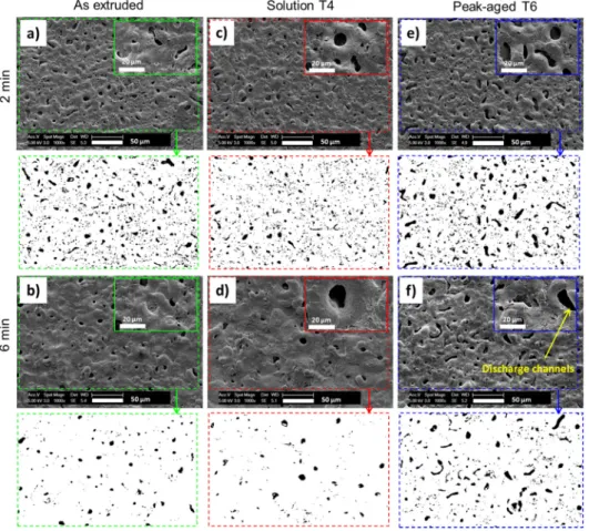
SEM micrographs inFig. 6compare the top-view aspects of the dif-ferent PEO coatings shown inFig. 4. All surfaces exhibit the typical mor-phology of the PEO coatings consisting in“pancake”-like structures with open pores of about 1–10 μm in diameter. Each of these holes, responsi-ble for the substantial amount of open porosity of the overall PEO coat-ing, is usually associated with a discharge channel that takes place during the PEO process [57,58].Fig. 6also evidences that, after 6 min, the solid solution T4 substrate results in larger size“pancakes” with larger open pores than the two substrates. Although the open pores
(i.e. discharge channels) exhibit quite the same size for all the sub-strates, they are far less numerous for the solution T4 substrate. Both the density of the discharge channels (defined as the number of dis-charge channels detected per surface unit) and the area fraction of the discharge channels were quantitatively estimated using SEM image analysis. A minimum of 10 different top-surface views (300μm × 300 μm) were considered for this estimation and the resulting error bars correspond to the standard deviation of the measurements.Fig. 7
shows the evolutions of the density of the discharge channels (Fig. 7a) and the associated area fraction (Fig. 7b) of the produced PEO coatings with the processing time. For all substrates, the density of discharge channels decreases as the PEO process goes on. This decrease is however faster for the solid solution T4 substrate than for the peak-aged T6 and the as-extruded substrates. After 6 min of processing, the density of dis-charge channels is less than 1 × 103mm−2for the T4 condition while it is
still about 3 × 103mm−2for the T6 condition (Fig. 7a). In addition, the
fraction area of the discharge channels for the T6 condition is always more than twice that for the T4 condition one. After 6 min of processing, this fraction area reaches about 3% and 8% for the substrates prepared under the T4 and T6 conditions, respectively (Fig. 7b).
Micro-hardness results carried out on the PEO oxide layers grown for 6 min are given inFig. 8. The evolutions of hardness with the load fol-low the same trend for the three different substrates. However interest-ing differences, with opposite trends, are revealed for the highest loads (for which the influence of the substrate becomes predominant) com-pared to the lowest applied load of 25 g (where the influence of the coating dominates). Consistently with the hardness values of the differ-ent substrates given inFig. 2and inTable 1, the hardness obtained at high loads (500 and 1000 g) confirm that the solution treated T4
Fig. 4. SEM micrographs of the cross-sections of the PEO oxide layers produced on the as-extruded substrate for (a) 2 min and (b) 6 min, on the solution (T4) substrate for (c) 2 min and (d) 6 min and on the peak-aged (T6) substrate for (e) 2 min and (f) 6 min.
substrate is softer than the as-extruded and T6 samples. Indeed, as men-tioned in section 3.1, these differences result from the heat treatments performed on the as-extruded magnesium substrate. On the one hand, in the absence of a significant fine precipitation, solutionising under T4 condition introduced a grain growth compared to the as-extruded condition resulting in a slight decrease in hardness (~86 HV for the as-extruded versus ~67 HV for the T4 treatment). On the other hand, for an equivalent grain size, peak aging under T6 condition generated pre-cipitation of intermetallic phases compared to the T4 condition leading to a high increase in hardness (~67 HV for T4 versus ~117 HV for T6). However, for the small penetration depth (in the range of ~ 1μm) ob-tained with the lowest indentation load of 25 g,Fig. 8reveals opposite PEO oxide layer hardness trends, which depend on the initial metallur-gical state of the substrate. Indeed, the hardness value evaluated from
the lowest indentation load of 25 g reaches about 641 HV (at 1.21μm penetration depth) for the softer solution treated T4 substrate; a value that is quite higher than the 572 HV (at 1.28μm penetration depth) and 541 HV (at 1.32μm penetration depth) obtained for the as-extruded and the peak-aged T6 conditions, respectively. Thus, these re-sults interestingly show that the softest solid solution T4 treated sub-strate generates, after PEO, the hardest coating.
3.3. Voltage-time response and light emission during PEO
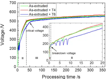
The voltage-time responses recorded during PEO process are given inFig. 9. For each initial metallurgical state, three voltage-time re-sponses were recorded, which showed a good reproducibility of the PEO processing. For all Mg substrates, the voltage variations with the
Fig. 6. SEM micrographs and the corresponding binary images (using ImageJ® software) of the top-surface of the PEO oxide layers produced on the as-extruded substrate for (a) 2 min and (b) 6 min, on the solution T4 substrate for (c) 2 min and (d) 6 min, and on the peak-aged T6 substrate for (e) 2 min and (f) 6 min.
Fig. 7. Time evolution of (a) the density (number per surface unit) of the discharge channels and (b) the fraction area of the discharge channels through the PEO coatings grown on the as-extruded, the solution T4 and the peak-aged T6 substrates.
processing time are usually described following three stages according to the increase rate of voltage. During thefirst 2 s (stage I inFig. 9), the voltage increases rapidly and linearly with time at a high rate (~200 V/s). During thisfirst stage, the partial dissolution of the substrate is accompanied by the formation of a thin passive insulatingfilm on the surface and intensive oxygen evolution. When the voltage reaches the dielectric breakdown threshold of the growing insulating film (~170 V), the PEO process enters into stage II. During this second stage, the voltage increase rate gets lower (~ 10 V/s) and numerous small-sized sparks spread over the entire processed surface. Within this sparking regime, the initial insulatingfilm is gradually transformed into the typical PEO coating as previously described in section 3.2. Inter-estingly, the voltage-time responses show somefluctuations (sudden drop and jump of the voltage) at the beginning of this second stage. Nu-merous and largefluctuations are observed for the peak-aged T6 sub-strate while they are quite inexistent for the solution T4 subsub-strate. Finally, after exceeding the critical voltage (~500 V), the PEO process en-ters into stage III that is featured by a lowest increase rate of voltage (~0.1 V/s). During this ultimate stage, the PEO coating continues grow-ing more or less rapidly dependgrow-ing on the Mg substrate. Indeed, it is noteworthy that during stages II and III, the solution T4 substrate always
exhibits a higher voltage value than the peak-aged T6 substrate. Since the voltage variations are usually related to the coating thickness and compactness, this suggests that thicker and compact coatings are ex-pected for the T4 substrate while slightly thinner and less compact coat-ing are achieved for the T6 substrate. This is in good agreement with the SEM observations previously presented in section 3.2 that evidence a thicker dense inner sublayer for the T4 substrate than for the T6 substrate.
Fig. 10compares chronograms of the light emission and the applied current at 2 min and 6 min of the PEO process for the different investi-gated substrates. After 2 min processing, the different chronograms de-pict the same kind of general features. The light emitted from the different samples is detected not only during the anodic alternation of the current, as usually encountered in PEO of aluminium [26], but also during the cathodic alternation (seeFig. 10a,c,e). Regardless of the na-ture of the processed substrate, the emission of the anodic light covers the whole anodic half-period while the cathodic light appears only in in-tense and successive bursts (of about less than 100μs in duration) at the beginning of the cathodic half-period (seeFig. 11). Light emission being directly associated to the presence of micro-discharges (MDs) over the processed surface, the chronograms inFig. 10suggest that MDs appear continuously and randomly under the anodic current while, compara-tively, they occur suddenly in short duration sequences at the beginning of the cathodic alternation. Interestingly, after 6 min, the recorded chro-nograms show substantial differences in the light emission behaviour depending on the initial metallurgical state of the PEO processed sub-strate. Indeed, after 6 min, no light is detected during the cathodic half-period for the solution treated T4 substrate. This is also rather true for the as-extruded condition (Fig. 10b,d). In contrast, the cathodic MDs are still present on the surface for the peak-aged T6 sample (Fig. 10f). Additionally, Fig. 10 also shows that the level of the light in-tensity emitted during the anodic half-period changes with the process-ing time, the light becomprocess-ing more intense at 6 min irrespective of the magnesium substrate. This indicates a stronger activity of the anodic MDs with the processing time as established by Martin et al. in the case of aluminium [23]. It is also worth noting that, after 6 min, the an-odic light emission is much more intense for the T4 condition (see
Fig. 10d) than for the as-extruded and the T6 ones (seeFig. 10b and
Fig. 10f, respectively).
From several chronograms like those given inFig. 10, an average value of the emission light intensity was determined over each of the anodic and the cathodic current alternations. For the different sub-strates investigated,Fig. 12a andFig. 12b compare the evolution of the average intensity of the anodic and cathodic emissions with the PEO processing time, respectively. Irrespective of the investigated substrate,
Fig. 12a clearly confirms that the anodic emission intensity increases faster, from the beginning of processing for the T4 condition and re-mains still largely higher during processing than for the other condi-tions.Fig. 12b also confirms that the intensity of the cathodic emission decreases faster with the processing time for the T4 condition than for the other ones. Ultimately, the extinction of the cathodic MDs occurs earlier for the T4 condition (after ~5 min) than for the as-extruded con-dition (after ~10 min). In other words, all these results reveal that the T4 solution treated magnesium promotes the occurrence of anodic MDs while inhibiting the occurrence of the cathodic ones. In contrast, a lower activity of anodic MDs and promotion of cathodic MDs are clearly visible for the T6 substrate containing a high density of precipitates. 4. Discussion
The overall results reported in section 3 clearly evidence two types of distinctive behaviour. Indeed, the substrate that contain precipitates (T6 conditions) results in a thin and porous PEO coating. On the other hand, the substrates in which the precipitates are dissolved (T4 condi-tion and in a lesser extend the as-extruded condicondi-tion) often exhibit op-posite trends in terms of micro-discharges (MDs) and mechanisms of
Fig. 8. Variation of the micro-hardness with depth measured with increasing indentation loads (25, 50, 100, 200, 300, 500 and 1000 g) on the top surface of the PEO coatings produced on the as-extruded, the solution T4 and the peak-aged T6 substrates.
Fig. 9. Voltage-time responses of PEO process conducted for (6 min) on the as- extruded substrate, on the solution (T4) substrate and on the peak-aged (T6) substrate.
coating formation, leading to fastest kinetics, thicker, more compact and harder PEO oxide layers. Thus, the discussion hereafter mainly aims at explaining the differences obtained for the T4 and T6 treated substrates. Thefirst section of this discussion will give a probable interpretation of the differences in the mechanism of coating formation depending on the nature of the substrate, whereas the second section will explain the consequences on the coating properties.
4.1. Effect of the substrate metallurgical state on the formation of PEO coatings
The formation mechanisms of the oxide layers produced by the PEO process can be discussed by considering the results on the behaviour of the MDs - that are known to strongly influence the growing oxide coat-ings - and by taking into account the appropriate literature works re-lated to the PEO of lightweight alloys, and more specifically magnesium and aluminium alloys.
First of all, the unusual appearance of cathodic MDs has already been observed and investigated under specific conditions by Nominé et al. and Rakoch et al. who PEO processed an EV31 magnesium alloy in fluo-ride containing electrolyte [59,60]. As for the present observations,
these authors highlighted the collective intermittent behaviour of the cathodic MDs that switch on and off once the cathodic current starts. Al-though the processing conditions used in the present study are quite different from those applied in Nominé's work [59], this specific inter-mittent behaviour of the cathodic MDs is also observed (seeFig. 11). More recently, using an alkaline-silicate electrolyte, which is closer in terms of chemistry than the electrolyte used in our experimental condi-tions, Nominé et al. detected not only the presence of these cathodic MDs but they also established their detrimental effect on the PEO layers building [61]. Indeed, the occurrence of cathodic MDs leads to a local spalling and to the formation of defects (mainly open porosities) through the coating while anodic MDs generate the formation of a more compact protective oxide coating. The present analysis confirms these pioneer results and demonstrates, in addition, that the occurrence and intensity of these anodic and cathodic MDs depend on the exact na-ture of the alloy substrate. In particular, the difference in behaviour is obviously clear between the substrate presenting a solid solution (T4) and those containing precipitates (in particular T6). In the case of the solution-treated substrate (T4), the main alloying elements Gd and Y are dissolved in the Mg matrix and are more likely to form– in contact with the alkaline electrolyte– fine oxide-like phases such as Gd2O3and
Y2O3at the metal surface in addition to the MgO oxide. Tekin et al. also
suggested the formation of RE-based oxide phases (typ. Nd2O3, Gd2O3)
through PEO coating on EV21 and WE43 Mg alloys, even if none of these phases were detected from XRD measurements [49]. Neverthe-less, although Gd2O3and Y2O3were also not detected from the present
XRD results (seeFig. 3), certainly due to their lower volume fraction as compared with MgO and Mg2SiO4, they are thermodynamically and
electrochemically expected to form [62–67]. Indeed, Gd and Y exhibit a high reactivity with oxygen due to their 3 oxidation state. They have larger negative Gibbs free energy of formation than other oxides (at 25 °C and 1 bar, ΔG°f,Gd203 = −1732 kJ/mol, ΔG°f,Y203 =
−1816 kJ/mol whereas ΔG°f,MgO = −569 kJ/mol) [62,63]. For example, it is also for these reasons that Gd is added in the chemical composition of specific stainless steels during casting at about 1500 °C since it forms preferentially gadolinium oxide (and also gadolinium sulfide) instead of undesirable non-metallic inclusions such as manganese sulphide (MnS) and chromium oxide (Cr2O3) [63]. In addition, from an electrochemical
point of view, Pourbaix E-pH diagrams of Gd and Y show that the oxida-tion of gadolinium and yttrium by water is possible at all pH values. This means that Gd and Y elements in solid solution through theα-Mg ma-trix and in contact with aqueous media spontaneously formed Gd2O3
and Y2O3oxides [64,65]. Several years ago, Gruss et al. experimentally
evidenced the formation of a rare-earth based oxide coatings [66,67]
Fig. 10. Chronograms of the of the light emission (coloured lines) and the corresponding current signal (black lines) recorded over one current pulse period for the as-extruded substrate (green lines) at (a) 2 min and (b) 6 min, for solution T4 substrate (red lines) at (c) 2 min and (d) 6 min, and for the peak-aged T6 substrate (blue lines) at (e) 2 min and (f) 6 min. (For interpretation of the references to colour in thisfigure legend, the reader is referred to the web version of this article.)
Fig. 11. Time evolution of the light emission (blue line) with the corresponding current signal (black line) recorded when the current polarity switches from positive to negative values for the peak-aged T6 substrate at 2 min of process. (For interpretation of the references to colour in thisfigure legend, the reader is referred to the web version of this article.)
by anodizing rare-earth metals (Sm, Gd, Dy, Ho, Er, Yb) and transition metal (Y) under sparking regime in silicate solutions using conditions very close to those of the present work. Conversely, in the case of the peak-aged substrate (T6), Gd and Y are retained and stabilized within the Mg24Y5and Mg5(GdY) intermetallic precipitates and are therefore
not available to form different oxides at the metal substrate surface. The effect of such differences in substrate nature and the combined
effects of the electrode voltage and the isoelectric point (IEP) on the be-haviour during the PEO process are conceptualized by the descriptive sketch inFig. 13.
Without any electrical biasing of the substrate, the sign of the surface charge is determined by the pH of the electrolyte with respect to the iso-electric point (IEP) of the solid oxides formed at the topmost surface. The IEP, also called the point of zero charge, represents the pH at
Fig. 12. Time variation of the average intensity of (a) the light emitted over one anodic half-period and (b) the light emitted over one cathodic half-period for the as-extruded substrate (green lines), for the solution T4 (red lines) and for the peak-aged T6 substrate (blue lines).
Fig. 13. Schematic model of possible combined effects of the PEO electrode biasing and the isoelectric point (IEP) on the surface charge through the electrical double layer (EDL) of the solution T4 (without Mg(GdY)-like precipitates) and the peak-aged T6 substrates (with Mg(GdY)-like precipitates). (For interpretation of the references to colour in thisfigure legend, the reader is referred to the web version of this article.)
which the surface charge equals zero [68–72]. From a general point of view, oxide coatings immersed in aqueous media get hydrated at their topmost surface and amphoteric groups form at their surface. These groups can catch or release a proton depending on the difference be-tween the IEP of the considered oxide and the pH of the solution (fur-ther details can be found in Ref. [70,71]). If the pH of the electrolyte is higher (respectively lower) than the IEP of the oxide, then the surface charges negatively (respectively positively). If the pH is exactly equal to the IEP of the oxide, the overall resulting surface charge remains equal to zero.
The IEP value strongly depends on the nature of the oxides present on the topmost surface of the substrate. Determined by classical electro-kinetic method, the IEP of MgO is about 12.3 (i.e. close to the pH of the electrolyte used in this study, pH = 12.6) while for Gd2O3
and Y2O3, the IEP is about 10.9 and 8.7, respectively [68,69].
Conse-quently, without any bias applied to the substrate, the nature of the sur-face charges is different for the solution T4 compared to the peak-aged T6 substrates. Indeed, in contact with air or with the basic electrolyte used, the dissolved Gd and Y elements in the T4 substrate are available to locally formfine Gd2O3and Y2O3oxides in addition to MgO.
Con-versely in the T6 substrate, Gd and Y are not available to form such ox-ides since they are retained within the stable Mg24Y5and Mg5(GdY)
intermetallic precipitates. Therefore, a mixture of MgO, Gd2O3and
Y2O3oxides is expected on the T4 substrate topmost surface (Fig. 13a)
while only MgO oxides can form on the T6 substrate (Fig. 13b). The resulting average IEP of the solution-treated T4 substrate remains prob-ably lower than that of the peak-aged T6 substrate. The pH of the elec-trolyte used in this study being of 12.6, negative charges are thus expected to form at the surface of the solution T4 substrate (Fig. 13c). In contrast, the surface charge should be close to zero for the peak-aged T6 substrate (Fig. 13d). Consequently, due to electrostatic counter-effects, the counter-ions from the electrolyte are localized in the vicinity of the oxide/electrolyte interface, through the electrical dou-ble layer (EDL). The counter-cations must face the negative charged sur-face of the solution T4 substrate leading to a thick EDL (Fig. 13c). On the contrary, very few counter-cations and counter-anions are specifically localized close to neutral charged surface of the peak-aged T6 substrate resulting in a very thin or quite inexistent EDL (Fig. 13d). These two dif-ferent initial situations will generate distinctive behaviour for the PEO process when the metallic substrate is further either positively or nega-tively biased. Indeed, the presence of a thick EDL can locally shield the external applied electricfield that is necessary for anodic and/or ca-thodic breakdown (e.g. breakdown could be delayed, less intense or never occur). In contrast, with a thin EDL that does not sufficiently shield the external applied electric field, breakdown occurs more favourably.
When the substrate is positively biased (i.e. during the anodic half-period of the current), negative ions move towards the oxide surface tending to accumulate at the oxide / electrolyte interface. In the case of the solution T4 substrate, negative ions replace the counter-cations that face the negatively charged surface but some of them are also re-pelled due to electrostatic forces (Fig. 13e). This effect of charge ex-change tends to mitigate the accumulation of excessive negative charges through the EDL. It results in a decrease in the EDL thickness that may become, at some locations over the surface, insufficient to shield the externally applied electricfield and ignition of anodic MDs can occur (Fig. 13e). However, because the accumulation of negative charges remains limited at the surface of the solution T4 substrate, it would be reasonable to expect MDs to follow a smooth behaviour (small size and short life-time) which is known to have a beneficial ef-fect on the growing oxide coating. This is in good agreement with exper-imental results on the growing oxide coating since they evidenced that the PEO coating on the T4 solution-treated substrate is thicker, more compact and covers more homogeneously the metal than that of the T6 peak-aged treated one (seeFigs. 4 and 5). For the latter, the peak-aged T6 substrate that carried a neutral charge at its surface without
bias, negative charges move easily through the very thin or quite inex-istent EDL and rapidly reach the oxide surface. Therefore, and oppositely to the solution T4 substrate, the accumulation of negative charge at the oxide surface is high and results in a strong reinforcement of the poten-tial difference on both sides of the oxide layer. Thus, the value of the local electricfield rapidly reaches and exceeds the breakdown field of the oxide layer. This promotes the appearance of intense anodic MDs (large size and long-life MDs) that are also known, like the cathodic MDs, to have a detrimental effect on the morphology of the growing oxide coating (e.g. high porosity) [23,26] (seeFigs. 4 and 5).
When the metal is negatively biased (i.e. during the cathodic half-period of the bipolar current), it is the turn of the positive ions from the electrolyte to be directed towards the oxide surface tending to accu-mulate at the oxide/electrolyte interface. In the case of the solution T4 substrate, these moving positive ions are repelled from the thick EDL due to electrostatic forces, especially by the counter-cations that face the negatively charged surface of the oxide layer (Fig. 13g). Thus, the EDL remains thick and the local electricfield through this EDL shields the external applied electricfield, preventing thereby the cathodic breakdown and the ignition of detrimental cathodic MDs. In contrast, in the case of the peak-aged T6 substrate, because the oxide surface carries a neutral charge without bias, positive ions move easily through the very thin or quite inexistent EDL and rapidly accumulate at the oxide layer surface. Consequently, this surface becomes rapidly charged with an excess of positive charges. The potential difference on both sides of the oxide layer gets high, reinforcing the external applied elec-tricfield, and promotes the appearance of the cathodic MDs that are known to have detrimental effects on the PEO oxide coatings (Fig. 13h). This is evidenced experimentally by the presence of numer-ous and large open pores through the PEO oxide coatings elaborated on the peak-aged T6 substrate (seeFig. 7).
Finally, the influence of the presence of precipitates on the mecha-nisms of the oxide layer formation has also been undoubtedly evi-denced in samples where segregated and unsegregated precipitates bands can be observed within the same substrate (illustrated in
Fig. 14). Indeed,Fig. 14shows the SEM cross-section of the PEO oxide layer produced on the peak-aged T6 substrate with a higher magni fica-tion than SEM micrographs presented inFig. 4. It shows a specific area, that was sometimes observed for some substrate, where the presence of local segregated bands of micrometre size precipitates (i.e. the Mg5
(GdY) cuboidal and the Mg24Y5spheroidal precipitates) aligned along
the extrusion direction, has generated strong heterogeneities in the local coating aspect.Fig. 14clearly evidences that the local segregated bands of precipitates are facing large open pores, the size of these open pores being very close to the width of the segregated bands. In
Fig. 14. SEM micrographs of the cross-sections of the PEO oxide layer produced on the peak-aged T6 substrate for 2 min.
contrast, bands depleted in precipitates are facing a thicker and a more compact coating. This heterogeneity in the PEO coating morphology can be discussed based on the same schematic model provided inFig. 13. As discussed above, this local heterogeneity of treatment can be explained by taking into account the possible combined effects of both the elec-trode biasing, the electrolyte pH and the resulting IEP of the oxide sur-face (with or without the presence of precipitates) on the PEO oxide layer morphology. In precipitate-free areas, the alloying elements Y and Gd are still available to formfine Y2O3and Gd2O3-like oxides
resulting in an average IEP lower than the electrolyte pH. As a conse-quence, the oxide surface exhibits a thick EDL that shields partly the ex-ternal applied electricfield and promotes the ignition of beneficial smoother anodic MDs while preventing the occurrence of detrimental cathodic MDs (seeFig. 13a,c,e,g). Thus, locally on the precipitate-free areas, the resulting PEO coating is thick and more compact (Fig. 14). Op-positely, locally in areas rich in precipitates, alloying elements Y and Gd are no longer available to form fine Y2O3 and Gd2O3-like oxides
resulting in an IEP close to the electrolyte pH. Under this condition, the EDL thickness at the oxide / electrolyte interface remains very thin or inexistent and does not sufficiently shield the external applied elec-tricfield, which promotes the ignition of detrimental strong anodic and cathodic MDs (seeFig. 13b,d,f,h). Thus, locally on the areas rich in precipitates, large open pores are visible that can be associated to the presence of strong MDs (seeFig. 14).
4.2. Effect of the substrate metallurgical state on the PEO coating properties As revealed by XRD, all coatings were composed of both the MgO crystallized magnesium oxide and the crystallized Mg2SiO4orthosilicate
forsterite. It is well established that Mg2SiO4is preferentially located
through the outer sublayer of the oxide coating while MgO mainly forms the dense inner sublayer [54,55]. However, significant variation in the coating thickness and hardness were obtained depending on the exact metallurgical state of the substrate (Fig. 5). After 2 min pro-cessing, the thickness of the overall oxide layer was already thicker for the solution-treated T4 sample than for the two other types of sub-strates. Ultimately, after 15 min processing, the overall thickness of the PEO coating on T4 solution-treated substrate (53μm) was almost twice that of the as-extruded treated one (26μm). The solid solution T4 substrate is also characterised by a lower open porosity level than the other substrates (Fig. 6andFig. 7). This can be understood by con-sidering that a solution-treated substrate promotes the occurrence of smooth anodic MDs (small size and short lifetime) that are known to have a positive effect of the coating built-up process while preventing the ignition of cathodic MDs. In contrast, for the peak-aged T6 substrate, the presence of precipitates promotes the appearance of both strong an-odic MDs (large size and long-life) and cathan-odic MDs that are known to have detrimental effects on the PEO oxide coatings. As these cathodic discharges are known to generate porosities [61], the porosity is higher for the precipitate containing T6 substrate than for the solution T4 substrate.
Another interesting observation of this work is that, while the solution-treated T4 substrate is the softest one, the hardness of the PEO oxide layer build on this T4 substrate (641 HV) is about 100 HV higher than the one built on the hardened T6 substrate (541 HV). There are several possible reasons for this. In addition to the presence of less numerous porosities for the solid solution-treated T4 substrate, the presence of a thicker dense inner sublayer (~8μm in thickness) for this substrate compared to the one obtained for the precipitate T6 sub-strate (~3μm in thickness) also likely plays a role. In addition, it should be clarified in a future study if the presence of a solid solution containing Gd and Y elements to build up the coating can either generate harder -solution strengthened– oxides or promote the presence of fine amounts of Gd2O3and/or Y2O3oxides (that could not be detected by XRD).
Finally, the present work also brings some new insight into the pro-cessing of Mg alloy parts. To get hard - precipitate strengthened - Mg
alloys covered by a hard and thick PEO layer, it seems important to per-form the PEO process on a solution-treated T4 alloy and apply the pre-cipitation hardening T6 treatment afterwards.
5. Conclusions
The effect of the metallurgical state of a magnesium substrate– mainly the absence and the presence of intermetallic precipitates– on the efficiency of the PEO process was investigated. To this end, the PEO process has been applied on a Gd, Y rare-earth containing magne-sium alloy GW103K for three metallurgical states: as-extruded, solutionising under T4 condition and peak-aged under T6 condition (fullβ’ precipitation). PEO was carried out in an alkaline silicate electro-lyte by applying a symmetrical pulsed bipolar current.
• The presence of precipitates in the peak-aged T6 substrate promotes the ignition of detrimental cathodic micro-discharges during the ca-thodic alternation of the pulsed bipolar current. In contrast, the ab-sence of precipitates in the solid solution T4 substrate inhibits their appearance while promoting the development of the beneficial an-odic micro-discharges. As a result, the PEO oxide coating produced on the solid solution T4 treated substrate was thicker, more compact and 100 HV harder than the one grown on the peak-aged T6 substrate. • Considering the relationship between the electrolyte pH, the isoelec-tric point (IEP) of the formed oxides and the initial metallurgical state of the magnesium substrate, a mechanism is proposed to explain the experimental results. For the solid solution T4 substrate, alloying elements (mainly Gd and Y) are available to locally formfine oxides (Gd2O3IEP = 10.9 and Y2O3IEP = 8.7 in addition to MgO oxide IEP
= 12.3) that shift the resulting average IEP to a value lower than that of the electrolyte pH (12.6). This allows building a thick electrical double layer at the oxide/electrolyte interface that prevents the igni-tion of detrimental cathodic micro-discharges. In contrast, for the peak-aged T6 substrate, the alloying elements that remain stabilized into intermetallic precipitates lead to a thin electrical double layer that is not sufficient to prevent from the formation of the detrimental cathodic micro-discharges.
• The successful development of protective PEO coatings requires the right management of the PEO process parameters (mainly the careful control of the electrolyte properties (e.g. pH) and the applied electri-cal conditions together with a particular attention to the prior sub-strate metallurgical heat treatment.
Acknowledgments
This work was supported by the French Government through the program“Investissements d'avenir” operated by the French National Research Agency (ANR) and referenced to as ANR-11-LABX-0008-01 (‘LabEx DAMAS’).
This work was also partly supported by the National Natural Science Foundation of China (51471109) and“111” project from China's Minis-try of Education (B16032).
The authors would like to acknowledge contributions of the following:
– C. Gendarme and the competence cluster on electron microscopy (CC 3M) at Institut Jean Lamour for providing advices in SEM obser-vations and EDX analyses.
– P. Boulet and the competence cluster on X-ray diffraction (CC-Xγ) at Institut Jean Lamour for providing advices in XRD measurements and analyses.
Data availability
The data that support thefindings of this study are available from the corresponding author, J. Martin, upon reasonable request.
Contribution of each author
J. Martin and T. Grosdidier have conceptualized the goal of this re-search work.
J.X. Zou has provided the samples.
G. Henrion, J. Martin and A. Nominé have conceived the experimen-tal rigs.
A.V. Nominé, J. Stef and J. Martin conducted most of the experiments. J. Stef and J. Martin performed the in-situ optical process diagnostics. A.V. Nominé and J. Martin performed all SEM analyses.
All the authors analysed the results and reviewed the manuscript. J. Martin and T. Grosdidier have prepared the manuscript. J. Martin and T.Grosdidier supervised the whole work. Additional information
The authors declare no competingfinancial interests. References
[1] B.L. Mordike, Creep-resistant magnesium alloys, Mater. Sci. Eng. A 324 (2002) 103–112.
[2] M. Navaneetha Krishna, S. Suresh, S.C. Vettivel, Characterization, formability, various stresses and failure analysis on workability of sintered Mg-5%B4C composite under triaxial stress state condition, J. Alloys Compd. 747 (2018) 324–339.
[3] J.F. Nie, Effects of precipitate shape and orientation on dispersion strengthening in magnesium alloys, Scr. Mater. 48 (2003) 1009–1015.
[4] I.P. Moreno, T.K. Nandy, J.W. Jones, J.E. Allison, T.M. Pollock, Microstructural stability and creep of rare-earth containing magnesium alloys, Scr. Mater. 48 (2003) 1029–1034.
[5] I.A. Anyanwu, S. Kamado, Y. Kojima, Aging characteristics and high temperature ten-sile properties of Mg-Gd-Y-Zr alloys, Mater. Trans. 42 (2001) 1206–1211.
[6] I.A. Anyanwu, S. Kamado, Y. Kojima, Creep properties of Mg-Gd-y-Zr alloys, Mater. Trans. 42 (2001) 1212–1218.
[7] S.M. He, X.Q. Zeng, L.M. Peng, X. Gao, J.J. Nie, W.J. Ding, Precipitation in a Mg-10Gd-3Y-0.4Zr (wt.%) alloy during isothermal ageing at 250 °C, J. Alloy. Compd. 421 (2006) 309–313.
[8] S.M. He, X.Q. Zeng, L.M. Peng, X. Gao, J.J. Nie, W.J. Ding, Microstructure and strength-ening mechanism of high strength Mg-10Gd-2Y-0.5Zr alloy, J. Alloy. Compd. 427 (2007) 316–323.
[9] V. Janik, D.D. Yin, Q.D. Wang, S.M. He, C.J. Chen, Z. Chen, C.J. Boehlert, The elevated-temperature mechanical behavior of peak-aged Mg-10Gd-3Y-0.4Zr alloy, Mater. Sci. Eng. A 528 (2011) 3105–3112.
[10] H.R.J. Nodooshan, W. Liu, G. Wu, Y. Rao, C. Zhou, S. He, W. Ding, R. Mahmudi, Effect of Gd content on microstructure and mechanical properties of Mg-Gd-Y-Zr alloys under peak-aged condition, Mater. Sci. Eng. A 615 (2014) 79–86.
[11]H.R.J. Nodooshan, W. Liu, G. Wu, R. Alizadh, R. Mahmudi, W. Ding, Microstructure characterization and high-temperature shear strength of the Mg-10Gd-3Y-1.2Zn-0.5Zr alloy in the as-cast and aged conditions, J. Alloy Compd. 619 (2015) 826–833.
[12] H.R.J. Nodooshan, G. Wu, W. Liu, G. Wei, Y. Li, S. Zhang, Effect of Gd content on high temperature mechanical properties of Mg-Gd-Y-Zr alloy, Mater. Sci. Eng. A 651 (2016) 840–847.
[13] M. Mondet, E. Barraud, S. Lemonnier, J. Guyon, N. Allain, T. Grosdidier, Microstruc-ture and mechanical properties of AZ91 magnesium alloy developed by spark plasma sintering, Acta Mater. 119 (2016) 55–67.
[14]X. Li, C. Liu, T. Al-Samman, Microstructure and mechanical properties of Mg-2Gd-3Y-0.6Zr alloy upon conventional and hydrostatic extrusion, Mater. Lett. 65 (2011) 1726–1729.
[15] J. Chang, X. Guo, S. He, P. Fu, L. Peng, W. Ding, Investigation of the corrosion for Mg-xGd-3Y-0.4Zr (x = 6, 8, 10, 12 wt%) alloys in a peak-aged condition, Corros. Sci. 50 (2008) 166–177.
[16] S. Liang, D. Guan, X. Tan, The relation between heat treatment and corrosion behav-iour of Mg-Gd-Y-Zr alloy, Mater. Des. 32 (2011) 1194–1199.
[17] A.L. Yerokhin, X. Nie, A. Leyland, A. Matthews, S.J. Dowey, Plasma electrolysis for sur-face engineering, Surf. Coat. Technol. 122 (1999) 73–93.
[18] Gh. Barati Darband, M. Aliofkhazraei, P. Hamghalam, N. Valizade, Plasma electrolytic oxidation of magnesium and its alloys: mechanism, properties and applications, J. Magnesium Alloy. 5 (2017) 74–132.
[19] M. Toorani, M. Aliofkhazraei, Review of electrochemical properties of hybrid coating systems on Mg with plasma electrolytic oxidation process as pretreatment, Surf. In-terface 14 (2019) 262–295.
[20]J. Dou, Y. Chen, H. Yu, C. Chen, Research status, of magnesium alloys by micro-arc oxidation: a review, Surf. Eng. 33 (2017) 731–738.
[21]F. Jaspard-Mécuson, T. Czerwiec, G. Henrion, T. Belmonte, L. Dujardin, A. Viola, J. Beauvir, Tailored aluminium oxide layers by bipolar current adjustment in the plasma electrolytic oxidation (PEO) process, Surf. Coat. Technol. 201 (2007) 8677–8682.
[22]E. Matykina, A. Berkani, P. Skeldon, G.E. Thompson, Real-time imaging of coating growth during plasma electrolytic oxidation of titanium, Electrochim. Acta 53 (2007) 1987–1994.
[23] J. Martin, A. Melhem, I. Shchedrina, T. Duchanoy, A. Nominé, G. Henrion, T. Czerwiec, T. Belmonte, Effects of electrical parameters on plasma electrolytic oxidation of alu-minium, Surf. Coat. Technol. 221 (2013) 70–76.
[24] P. Bala Srinivasan, J. Liang, R.G. Balajeee, C. Blawert, M. Störmer, W. Dietzel, Effect of pulse frequency on the microstructure, phase composition and corrosion perfor-mance of a phosphate-based plasma electrolytic oxidation coated AM50 magnesium alloy, Appl. Surf. Sci. 256 (2010) 3928–3935.
[25] V. Dehnavi, B.L. Luan, D.W. Shoesmith, X.Y. Liu, S. Rohani, Effect of duty cycle and ap-plied current frequency on plasma electrolytic oxidation (PEO) coating growth be-haviour, Surf. Coat. Technol. 226 (2013) 100–107.
[26] J. Martin, A. Nominé, F. Brochard, J.-L. Briançon, C. Noël, T. Belmonte, T. Czerwiec, G. Henrion, Delay in micro-discharges appearance during PEO of Al: evidence of a mechanism of charge accumulation at the electrolyte/oxide interface, Appl. Surf. Sci. 410 (2017) 29–41.
[27] J.J. Zhuang, R.G. Song, N. Xiang, Y. Xiong, Q. Hu, Effect of current density on micro-structure and properties of PEO ceramic coatings on magnesium alloy, Surf. Eng. 33 (2017) 744–752.
[28] F. Muhaffel, H. Cimenoglu, Development of corrosion and wear resistant micro-arc oxidation coating on a magnesium alloy, Surf. Coat. Technol. 357 (2019) 822–832.
[29] R. Arrabal, E. Matykina, F. Viejo, P. Skeldon, G.E. Thompson, Corrosion resistance of WE43 and AZ91D magnesium alloys with phosophate PEO coatings, Corros. Sci. 50 (2008) 1744–1752.
[30] S. Stojadinović, R. Vasilić, J. Radić-Perić, M. Périć, Characterization of plasma electro-lytic oxidation of magnesium alloy AZ31 in alkaline solution containingfluoride, Surf. Coat. Technol. 273 (2015) 1–11.
[31] K.O. Gunduz, Z.C. Oter, M. Tarakci, Y. Gencer, Plasma electrolytic oxidation of binary Mg-Al and Mg-Zn alloys, Surf. Coat. Technol. 323 (2017) 72–81.
[32] L. Wang, L. Chen, Z. Yan, H. Wang, J. Peng, Effect of potassiumfluoride on structure and corrosion resistance of plasma electrolytic oxidationfilms formed on AZ31 magnesium alloy, J. Alloy. Compd. 480 (2009) 469–474.
[33] R. Arrabal, A. Pardo, M.C. Merino, M. Mohedano, P. Casajús, E. Matykina, P. Skeldon, [34] G.E. Thompson, Corrosion behaviour of a magnesium matrix composite with a
sili-cate plasma electrolytic oxidation coating, Corros. Sci. 52 (2010) 3738–3749.
[35] F. Simchen, M. Sieber, T. Lampke, Electrolyte influence on ignition of plasma electro-lytic oxidation processes on light metals, Surf. Coat. Technol. 315 (2017) 205–213.
[36] D. Chen, R. Wang, Z. Huang, Y. Wu, Y. Zhang, G. Wu, D. Li, C. Guo, G. Jiang, S. Yu, D. Shen, P. Nash, Evolution processes of the corrosion behavior and structural charac-teristics of plasma electrolytic oxidation coatings on AZ31 magnesium alloy, Appl. Surf. Sci. 434 (2018) 326–335.
[37] X. Tu, C. Miao, Y. Zhang, Y. Xu, J. Li, Plasma electrolytic oxidation of magnesium alloy AZ31B in electrolyte containing Al2O3sol as additives, Materials 11 (2018) 1618–1629.
[38] D. Jiang, H. Zhou, S. Wan, G.Y. Cai, Z.H. Dong, Fabrication of superhydrophobic coat-ing on magnesium alloy with improved corrosion resistance by combincoat-ing micro-arc oxidation and cyclic assembly, Surf. Coat. Technol. 339 (2018) 155–166.
[39] B.S. Lou, Y.Y. Lin, C.M. Tseng, Y.C. Lu, J.G. Duh, J.W. Lee, Plasma electrolytic oxidation coatings on AZ31 magnesium alloys with Si3N4 nanoparticles additives, Surf. Coat. Technol. 332 (2017) 358–367.
[40] W.R. Osório, N. Cheung, J.E. Spinelli, P.R. Goulart, A. Garcia, The effects of a eutectic modifier on microstructure and surface corrosion behavior of Al-Si hypoeutectic al-loys, J. Solid State Electr. 11 (2007) 1421–1427.
[41] S. Gudic, L. Vrsalovic, M. Kliskic, I. Jerkovic, A. Rodonic, M. Zekic, Corrosion inhibition of AA 5052 Aluminium alloy in NaCl solution by different types of honey, Inter. J. Electrochem. Sci. 11 (2016) 998–1011.
[42] Y. Song, E.H. Han, K. Dong, D. Shan, C.D. Yim, B.S. You, Microstructure and protection characteristics of the naturally formed oxidefilms on Mg-xZn alloys, Corros. Sci. 72 (2013) 133–143.
[43] D.M. Rosa, J.E. Spinelli, W.R. Osório, A. Garcia, Effects of cell size and macrosegregation on the corrosion behavior of a dilute Pb-Sb alloy, J. Power Sources 162 (2006) 696–705.
[44] Y.Q. Wang, X.J. Wang, T. Zhang, K. Wu, F.H. Wang, Role ofβ phase during microarc oxidation of Mg alloy AZ91D and corrosion resistance of the oxidation coating, J. Mater. Sci. Technol. 29 (2013) 1129–1133.
[45] Y. Chen, Y. Yang, W. Zhang, T. Zhang, F. Wang, Influence of second phase on corro-sion performance and formation mechanism of PEO coating on AZ91 Mg alloy, J. Al-loys Compd. 718 (2017) 92–103.
[46] R.F. Zhang, S.F. Zhang, Formation of micro-arc oxidation coatings on AZ91HP mag-nesium alloys, Corros. Sci. 51 (2009) 2820–2825.
[47] S.F. Zhang, R.F. Zhang, W.K. Li, M.S. Li, G.L. Yang, Effects of tannic acid properties of anodic coatings obtained by micro arc oxidation on AZ91 magnesium alloy, Surf. Coat. Technol. 207 (2012) 170–176.
[48] O. Khaselev, D. Weiss, J. Yahalom, Structure and composition of anodicfilms formed on binary Mg-Al alloys in KOH-aluminate solutions under continuous sparking, Corros. Sci. 43 (2001) 1295–1307.
[49] K.M. Lee, Y.G. Ko, D.H. Shin, Effect of icosahedral phase on growth behaviour of thin oxidefilm on MgZn12Y1.7 alloy via micro arc oxidation, Thin Solid Films 531 (2013) 261–265.
[50] K.C. Tekin, U. Malayoglu, S. Shrestha, Electrochemical behavior of plasma electrolytic oxide coatings on rare earth element containing Mg alloys, Surf. Coat. Technol. 236 (2013) 540–549.
[51]C. Liu, T. Xu, Q. Shao, S. Huang, B. Jiang, J. Liang, H. Li, Effects of beta phase on the growth behavior of plasma electrolytic oxidation coating formed on magnesium al-loys, J. Alloys Compd. 784 (2019) 414–421.
[52]P. Wang, J. Li, Y. Guo, Z. Yang, Growth process and corrosion resistance of ceramic coatings of micro-arc oxidation on Mg-Gd-Y magnesium alloys, J. Rare Earth. 28 (2010) 798–802.
[53] S.K. Kang, J.Y. Kim, C.P. Park, H.U. Kim, D. Kwon, Conventional Vickers and true in-strumented indentation hardness determined by inin-strumented indentation tests, J. Mater. Res. 25 (2010) 337–343.
[54] Y. Samih, G. Marcos, N. Stein, N. Allain, E. Fleury, C. Dong, T. Grosdidier, Microstruc-ture modifications and associated hardness and corrosion improvements in the AISI 420 martensitic stainless steel treated by high current pulsed electron beam (HCPEB), Surf. Coat. Technol. 259 (2014) 737–745.
[55]S.V. Gnedenkov, O.A. Khrisanfova, A.G. Zavidnaya, S.L. Sinebryukhov, V.S. Egorkin, M.V. Nistratova, A. Yerokhin, A. Matthews, PEO coatings obtained on an Mg-Mn type alloy under unipolar and bipolar modes in silicate-containing electrolytes, Surf. Coat. Technol. 204 (2010) 2316–2322.
[56] P. Bala-Srinivasan, J. Liang, C. Blawert, M. Störmer, W. Dietzel, Effect of current den-sity on the microstructure and corrosion behaviour of plasma electrolytic oxidation treated AM 50 magnesium alloy, Appl. Surf. Sci. 255 (2009) 4212–4218.
[57] D. Veys-Renaux, E. Rocca, J. Martin, G. Henrion, Initial stages of AZ91 Mg alloy micro-arc anodizing: growth mechanisms and effect on the corrosion resistance, Electrochim. Acta 124 (2014) 36–45.
[58]J.A. Curran, T.W. Clyne, Thermo-physical properties of plasma electrolytic oxide coatings on aluminium, Surf. Coat. Technol. 199 (2005) 168–176.
[59] J.A. Curran, T.W. Clyne, Porosity in plasma electrolytic oxide coatings, Acta Mater. 54 (2006) 1985–1993.
[60] A. Nomine, J. Martin, C. Noël, G. Henrion, T. Belmonte, I.V. Bardion, V.L. Kovalev, A.G. Rakoch, The evidence of cathodic micro-discharges during plasma electrolytic oxi-dation process, Appl. Phys. Lett. 104 (2014), 081603.
[61] A.G. Rakoch, A.A. Gladkova, Z. Linn, D.M. Strekalina, The evidence of cathodic discharges during plasma electrolytic oxidation of light metallic alloys and micro-discharge intensity depending on pH of the electrolyte, Surf. Coat. Technol. 269 (2015) 138–144.
[62] A. Nominé, J. Martin, G. Henrion, T. Belmonte, Effect of cathodic micro-discharges on oxide growth during plasma electrolytic oxidation (PEO), Surf. Coat. Technol. 269 (2015) 131–137.
[63] R.A. Robie, B.S. Hemingway, J.R. Fisher, Thermodynamic properties of minerals and related substa,ces at 298.15° K and 1 bar (105 pascals) pressure and at higher tem-peratures, U.S. Geol. Surv. Bull. 1452 (1979).
[64] J.H. Ahn, H.D. Jung, J.H. Im, K.H. Jung, B.M. Moon, Influence of the addition of gado-linium on the microstructure and mechanical properties of duplex stainless steel, Mater. Sci. Eng. A 658 (2016) 255–262.
[65] A. Jukic, M. Metikos-Hukovic, The hydrogen evolution reaction on pure and polypyrrole-coated GdNi4Al electrodes, Electrochim. Acta 48 (2003) 3929–3937.
[66]M. Pourbaix, Atlas of Electrochemical Equilibria in Aqueous Solutions, Pergamon Press, Oxford, 1966.
[67] L. Gruss, T. Mackus, The anodic oxidation of several rare earth metals in sodium alu-minate solution, J. Electrochem. Soc. Electrochem. Sci. Technol. 120 (1973) 337–340.
[68] L. Gruss, T. Mackus, The anodization of several rare earth metals in sodium silicate solutions, J. Electrochem. Soc. Electrochem. Sci. Technol. 121 (1974) 1402–1405.
[69] G. Parks, The isoelectric points of solid oxides, solid hydroxides, and aqueous hydroxo complex systems, Chem. Rev. 65 (1965) 177–198.
[70] M. Kosmulski, pH-dependent surface charging and points of zero charge. IV. Update and new approach, J. Colloid Interf. Sci. 337 (2009) 439–448.
[71] P. Lukes, M. Clupek, V. Babicky, P. Sunka, The role of surface chemistry at ceramic/ electrolyte interfaces in the generation of pulsed corona discharges in water using ceramic-coated rod electrodes, Plasma Process. Polym. 6 (2009) 719–728.
[72] A. Nominé, J. Martin, C. Noël, G. Henrion, T. Belmonte, I.V. Bardin, P. Lukès, Surface charge at the oxide/electrolyte interface: toward optimization of electrolyte compo-sition for treatment of aluminium and magnesium by plasma electrolytic oxidation, Langmuir 32 (2016) 1405–1409.