Ductile Fracture and Structural Integrity of
Pipelines & Risers
by
Kirki N. Kofiani
Submitted to the Department of Mechanical Engineering
in partial fulfillment of the requirements for the degree of
ARCHIv_/r?'
Doctor of Philosophy in Mechanical Engineering
VHOLOCGYat the
APR 16 2313]
MASSACHUSETTS INSTITUTE OF TECHNOLOGY
February 2013
RARIES
©
Massachusetts Institute of Technology 2013. All rights reserved.
Author .
. ... ... . ... .. ... ...Department of Mechanical Engineering
January 1, 2013
Certified by
... ,..-..- . .1; '= Y ... ... ... . ...Tomasz Wierzbicki
Professor, Applied Mechanics, Committee Chairman
(~~(fffesiSjJpervisor
Certified by ...
Paul D. Sclavounos
Professor, Mechanical Engineering & Naval Architecture, Committee
Member
~({
/
/---)
Thesis Supervisor
C ertified by ...
,....
I.. ... ...
Henry S. Marcus
Professor, Mechanical Engineering & Marine Systems, Committee
/
I
Member
on fhejp.upervisor
A ccepted by ...
...
David E. Hardt
Chairman, Department Committee on Graduate Thesis
Ductile Fracture and Structural Integrity of Pipelines &
Risers
by
Kirki N. Kofiani
Submitted to the Department of Mechanical Engineering on January 1, 2013, in partial fulfillment of the
requirements for the degree of
Doctor of Philosophy in Mechanical Engineering
Abstract
The Oil and Gas (O&G) industry has recently turned its interest towards deep and ultra-deep offshore installations in order to address the global increase of energy de-mand. Pipelines and risers are key components for the production and transportation of oil and gas both in the offshore and onshore environment. The structural integrity and fracture control of pipes, which are major components for the exploration, pro-duction and transportation of fossil fuels have been the subject of extensive analysis in the past decade using classical fracture mechanics approaches, especially for the offshore case. The main driving force for this line of research was the fact that both the cost and the technical challenges increase disproportionally with water depth. In the deep and ultra-deep water environment the technical challenges include higher permanent and operational loads, extreme environmental conditions and the presence of corrosive agents. All the above mentioned parameters demand the use of modern fracture mechanics approaches. At the same time, the inaccessibility to structures lo-cated at depths of two to three kilometers, results in extreme repair costs. Due to the magnitude of environmental and financial consequences in the event of failure, the industry has established extremely conservative safety requirements resulting from outdated approaches for those types of structures. Furthermore, the O&G indus-try is reluctant to adopt novel fracture models, unlike other industries, such as the automotive and aerospace. Pipelines and risers need to be evaluated both from a structural and a financial perspective. The current thesis is proposing a new physics-inspired technology and computational capability for the prediction of fracture and structural failure of pipelines and risers operating in extreme conditions, such as deep and ultra-deep water environments subjected to extreme conditions and accidental loads. The computational tool employed in the current study is derived from a vari-ational principle, combined with a cumulative measure of damage that is developed to control the fracture initiation. The calibration process of this methodology is achieved through a hybrid numerical experimental procedure. The material selection for this study was chosen naturally from the O&G and pipeline community. Tra-ditionally, the O&G and pipeline industries have been using not only conventional
fracture methods, but also conventional low-grades of steels for pipelines and risers, such as X60 and X70. However, deep and ultra-deep applications and the demand for increase of daily flow production pose new challenges in terms of harsh environmental conditions, increase of external diameter and higher operational loads. The industry is well aware of the fact that Advance High Strength Steels (AHSS), such as X100 and
X120, can address those issues, but is not yet ready to introduce them, due to
incom-plete understanding of their material properties and structural behavior in the plastic and near failure range. Therefore, the current thesis offers a comprehensive study of two representative grades from both categories (X70 and X100), comparing their me-chanical properties and completing a preliminary analysis quantifying the financial difference between the two for pipeline construction. Pipeline and riser installations are extremely capital intensive. They need to be evaluated both from a structural and a financial perspective, so that operating companies can quantify the integrity of their investments. The proposed thesis will develop a method using representations of oil prices and material costs along with a fracture mechanics model to improve the decision process of the material, the design, and the operating conditions of pipeline installations. This technique will not only attempt to account for the mechanical properties and structural integrity of the tubular component of interest but also to quantify the financial benefit of AHSS in the Oil and Gas community.
Thesis Supervisor: Tomasz Wierzbicki
Title: Professor, Applied Mechanics, Committee Chairman Thesis Supervisor: Paul D. Sclavounos
Title: Professor, Mechanical Engineering & Naval Architecture, Committee Member Thesis Supervisor: Henry S. Marcus
Acknowledgments
First of and foremost, I would like to thank my advisors Professor Tomasz Wierzbicki,
Professor Henri Marcus and Professor Paul Sclavounos for their guidance, encourage-ment and discussions on both research and non-research related matters. Especially,
I would like to thank Professor Wierzbicki who taught me the importance of
real-world applications, the significance of collaborations both within our lab and in the wide-academic community. This thesis would not have been possible without the support of Dr. Young-Woong Lee, who believed in this project early on and sup-ported this work through the MIT/Shell project. Acknowledgements are also due to Dr. Bo Cerup Simonsen for his contribution to the project and for offering me the first real world perspective on my work and Dr. Aida Nonn that has been a valuable colleague, advisor and friend. Also, I want to deeply thank the VFRL and ICL fam-ilies for their immense contribution in my transformation from a Hydro researcher to an Experimental and Computational Fracture Mechanics researcher. Especially, I would like to thank Wenting Xiao (Dr.), Sankha Banerjee (Dr.), Grgur Tokic, Tea
Zakula, Bryce Campbell, Meng Liu (Dr), Elham Sahraei (Dr.), Allison Beese (Dr.),
Matthiew Dunand, Stephane Marcadet, Kai Wang, Keun Hwan Pack and Xiaowei Zhang for the support, discussions and long explanations of initially foreign concepts and also Themis Resvanis for the jump-start of this project with the ROV picture of the Deepwater Horizon leak location. I owe additional thanks to Ms. Barbara Smith for her amazing help in all types of problems and matters during my PhD years and for her (and dear Benjamin's) encouragement in times of extreme stress. I would also like to thank my immediate and extended family/friends for their love and support on this work. Specifically, thanks are due to my cousins Konstantina and Theodora and Eleni for teaching me humility and forgiveness, Anastasia Kefiridou and Giorgos Papadakos for offering to me their unconditional love and support, my closest friends Eirini Liotou, Ivi Tsantili and Konstantina Georgaki for their time and encourage-ment, my thesis group Dr. Hsi, Gabie, Timea and Razan. Also, Chun for inspiring and guiding me towards becoming a Fracture Mechanics researcher, my mother and
father for teaching me perseverance and self-worth, my grandmother who taught me human kindness and my grandfather who taught me honor. This worked would have been impossible with out you all.
Contents
A bbreviations . . . .. . . . .
1 Introduction
1.1 Setting the Background for the Research . . . . . 1.2 Pipelines and Risers . . . . 1.3 Structural Integrity of Pipelines and Risers . . . . 1.4 Major Pipeline and Riser Problems . . . . 1.4.1 Aging of Oil & Gas Infrastructure . . . . . 1.4.2 Trend towards API AHSS Grades of Steel 1.5 Thesis Outline . . . .
2 Oil & Gas Pipelines and Risers
2.1 Manufacturing Process of Pipelines and Risers 2.1.1 Seamless pipes . . . . 2.1.2 Welded pipes . . . . 2.2 Material Selection for Pipelines and Risers . . . . 2.3 Installation Methods for Offshore Pipelines . . . . 2.4 Loading of Pipelines and Risers . . . .
3 Structural Integrity against Ductile Fracture of Oil & and Risers
3.1 Structural Integrity against Ductile Fracture . . . .
3.2 Classical Standards and Guidelines on Fracture . . . . 3.2.1 Toughness testing . . . . Gas Pipelines 70 . . . . 70 . . . . 74 . . . . 74 32 36 . . . . 36 . . . . 42 . . . . 45 . . . . 48 . . . . 50 . . . . 50 . . . . 5 2 56 . . . . 57 . . . . 5 7 . . . . 6 1 . . . . 65 . . . . 6 7 . . . . 67
3.2.2 Small-scale testing . . . .
3.2.3 Large-scale testing . . . . 3.2.4 Classification Societies . . . .
3.3 Joint Industrial Projects on Structural Integrity and Fracture Control 3.4 Research Projects on Structural Integrity and Fracture Control . . . .
3.5 Modern Approaches to Ductile Fracture . . . . 3.6 Objectives and Contribution . . . .
4 Mechanical Properties of API Grades X70 and X100 4.1 Theoretical Part . . . .
4.1.1 Plasticity modeling . . . .
4.1.2 Fracture Criterion . . . . 4.2 Experimental Part . . . . 4.2.1 Preparation of specimens . . . . 4.2.2 Description of experimental apparatus and digital in lation . . . .
4.2.3 Metallurgical and chemical analysis . . . .
4.2.4 Plasticity . . . .
4.2.5 Fracture . . . ..
4.3 Numerical Part . . . . 4.3.1 Comparison of experimental and numerical results . 4.3.2 Calibration process . . . . 4.3.3 Sensitivity analysis . . . . 94 . . . . 94 . . . . 96 . . . . 98 . . . . 102 . . . . 102 age corre-. corre-. corre-. corre-. corre-. corre-. 105 . . . . 110 . . . . 113 . . . . 124 . . . . 133 . . . . 135 . . . . 137 . . . . 146
5 Validation of Novel Approach of
Structural Integrity on Pipelines and Risers
5.1 Fracture resistance prediction of SENT specimens . . . .
5.1.1 Introduction . . . .
5.1.2 Crack Driving Force and R-curves . . . .
5.1.3 Problem Description and Numerical Model . . . . 5.1.4 Resistance Curves and Fracture Surface Evolution . . . .
75 77 78 80 83 87 90 154 154 155 156 159 163
5.1.5 SENT for the Prediction of Pipe Crack Resistance . . 5.1.6 Conclusions . . . . 5.2 Prediction of Bursting Pressure of Pipelines . . . . 5.2.1 Yield Pressure assessment of Large-Scale Pipelines . . 5.2.2 Numerical Model and Problem Description . . . . 5.2.3 Effect of Anisotropy on the onset of fracture location 5.2.4 Effect of thickness on the bursting pressure . . . .
165 168 169 169 174 176 177 5.2.5 Conclusion . . . . 182
5.3 Emergency Shearing for Oil Leak Prevention . . . . 183
5.3.1 Problem Description and Numerical Model . . . . 187
5.3.2 Shearing Surface Representation and Shearing Force Prediction 189 5.3.3 History of Stress Triaxiality . . . . 192
5.3.4 Conclusions . . . . 193
5.4 Deepwater Horizon Platform Sinking Reconstruction . . . . 195
5.4.1 Problem Description and Numerical Model . . . . 195
5.4.2 Leak location Prediction . . . . 198
5.4.3 History of Stress Triaxiality . . . . 200
5.4.4 Conclusions . . . . 202
6 Financial Analysis Pipelines and Risers
6.1 Current Approaches for Asset Valuation and Financial P ipelines . . . .
Analysis of
6.2 Financial Evaluation of Pipelines & Risers with Structural Integrity
Input... ...
6.2.1 Effect of Material Price . . . .
6.2.2 Effect of Discount Rate . . . .
6.3 Evaluating the API Trend towards Advanced High Strength Steels . . 6.3.1 Oil & Gas Infrastructure Evaluation Process . . . . 6.4 Conclusions . . . . 204 207 211 216 219 223 225 227
7 Conclusions and Recommendations 230
7.1 Summary of results ... ... 230
7.2 Contributions . . . . 231
7.2.1 MIT fracture technology for API grades . . . . 232
7.2.2 Introduction of round notched fracture specimens . . . . 233
7.2.3 SENT versus MIT fracture technology for crack resistance pre-diction . . . . 234
7.2.4 Prediction of bursting pressure of pressurized pipelines . . . . 234
7.2.5 Prediction of failure in risers subjected to extreme accidental loading . . . . 235
7.2.6 Technical Analysis combined with Finance . . . . 235
7.3 MIT Fracture Technology for Pipes . . . . 236
7.4 Recommendations on Pipelines & Risers . . . . 237
List of Figures
1-1 Deepwater Horizon accident negative effect on market value of compa-nies associated with the oil spill [84]. . . . . 39
1-2 Oil demand predictions for different market projection scenarios rang-ing from conservative to optimistic [28]. . . . . 39 1-3 Exploration and production trend towards deep and ultra deepwater
territories [68]. . . . . 40 1-4 Percentage breakdown of main failure causes the US pipeline
infras-tructure [52]. . . . . 41
1-5 Comparison of transportation cost between major logistics methods for petroleum . . . . 43
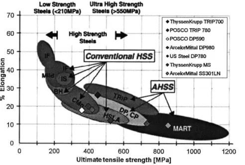
1-6 Trend towards AHSS observed in the automotive industry. . . . . 51 1-7 Trend towards AHSS observed for API pipeline grades of steel. ... 52
2-1 Seamless pipe manufacturing process as a function of outside diameter
and thickness [64]. . . . . 58
2-2 Schematic representation of the pilger mill manufacturing process [64]. 59 2-3 Schematic representation of the plug mill manufacturing process [64]. 60
2-4 Schematic representation of the continuous mandrel mill manufactur-ing process [64]. . . . . 60 2-5 Schematic representation of the continuous push bench manufacturing
process [64]. . . . . 61 2-6 Schematic representation of the spiral weld mill manufacturing process
2-7 Schematic representation of the ERW manufacturing process [64]. . 63
2-8 Schematic representation of the UOE manufacturing process [64]. . 64
2-9 ICL characterized materials inserted in the automotive trend banana p lot. . . . . 65
2-10 Combination of the automotive and pipeline trend towards advanced high strength grades of steel. . . . . 66
3-1 The three typical fracture modes i) Opening, ii) Sliding and iii) Tearing. 72
3-2 Typical graphical representation of Charpy V notched test. . . . . 75 3-3 SENT specimen sketch with pin loading applied at the ends of the
specim ens. . . . . 76
3-4 Full-scale multi-Axial Load Testing Machine [Courtesy of CSM]. . . . 78 3-5 Bulging pipe subjected to internal pressure taken from [40] . . . . 90
4-1 Two different types of fracture mechanisms controlled respectively by the shear stress and normal stress and their combination. . . . . 99
4-2 X70 (left) and X100 (right) pipe segment as received with cuboid cutouts. 103
4-3 Graphical representation of steps 2 and 3 for the extraction of speci-mens with respect to the longitudinal direction of the pipe. . . . . 103
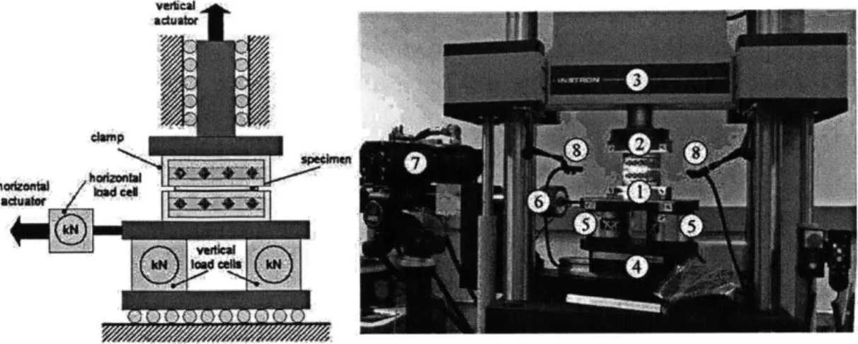
4-4 Main components of ICL, Instron 8080 customized dual actuator test-ing equipment. . . . . 106
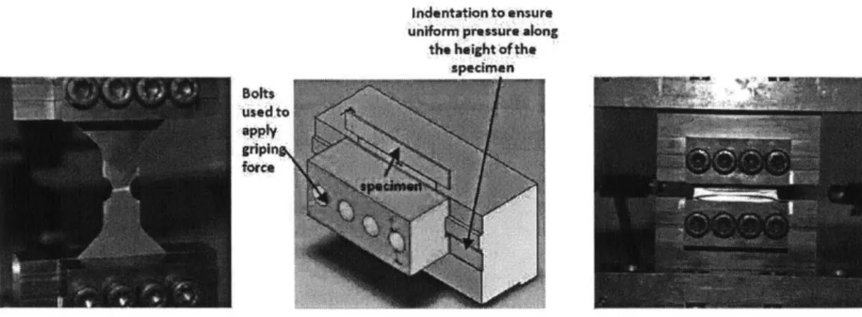
4-5 Instron 8080 customized pressure grips used for tensile test of a notched X100 specimen (left), schematic of the grip design (middle) and shear test of a butterfly X70 specimen (right). . . . . 107
4-6 Schematic representation of dual actuator Instron 8080 with customized pressure grips (left), ICL biaxial testing facility (right). . . . . 107
4-7 MTS uniaxial tensile wedge grips, b) MTS circular grips and die used for punch testing. . . . . 108
4-8 2D DIC monitoring the displacement field of flat specimen (left) and
4-9 Example of speckle pattern on a dogbone specimen and indication of virtual vertical and horizontal extensometers. . . . . 110
4-10 Surface microstructure analysis of API X70 by Salzgitter Mannesmann Forschung. . . . . 111
4-11 Microstructure of X100 from LOM (left) and SEM (right) analyses. . 113
4-12 Force versus displacement of dogbone specimen experimental data for
A PI X 70 steel . . . . 118
4-13 Force versus displacement of dogbone specimen experimental data for
API X 100 steel. . . . . 119
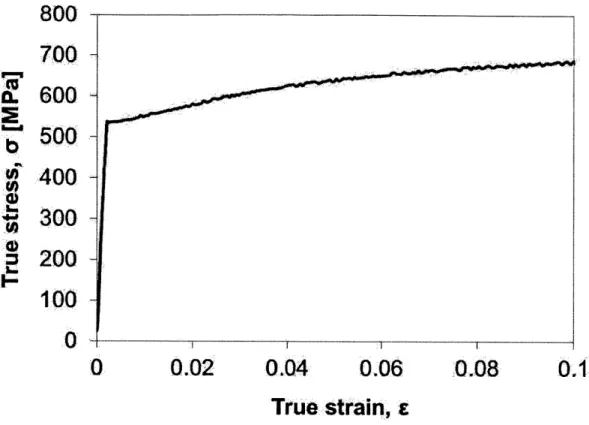
4-14 Calculated true stress versus strain curve of dogbone specimen for API
X70 grade of steel. . . . . 120
4-15 Calculated true stress versus strain curve of dogbone specimen for API
X100 grade of steel. . . . . 121
4-16 Hardening rule fitting for the longitudinal dogbone tensile specimen
made by API X70. . . . . 122
4-17 Hardening rule fitting for the longitudinal dogbone tensile specimen
made by API X100. . . . . 123
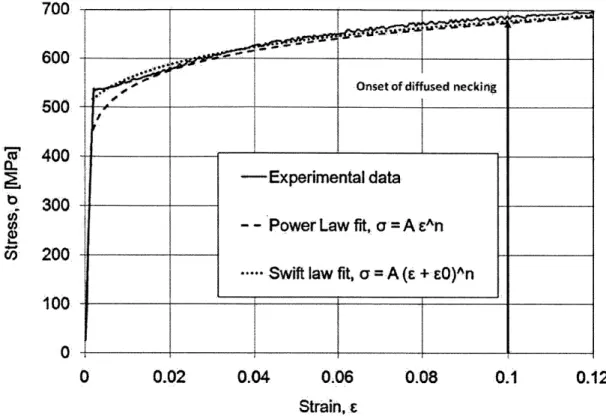
4-18 Material behavior after initiation of diffused necking for X70. . . . . . 124
4-19 Material behavior after initiation of diffused necking for X100. .... 125
4-20 Load vs. displacement curve from punch simulations for X70. .... 126
4-21 Load vs. displacement curve from punch simulations for X100. . . . . 126
4-22 Force versus displacement for three principal directions of X70 (left)
and X 100 (right). . . . . 127
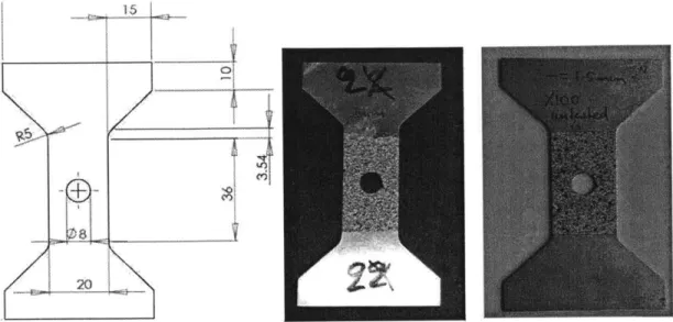
4-23 Blueprints of flat specimens with central hole and dyed specimens used
for API X70 and X100. . . . . 128
4-24 Instron 8080 customized pressure grips used for tensile test of a notched specimen (left), schematic of the grip design demonstrated in the case of a butterfly specimen . . . . . 128
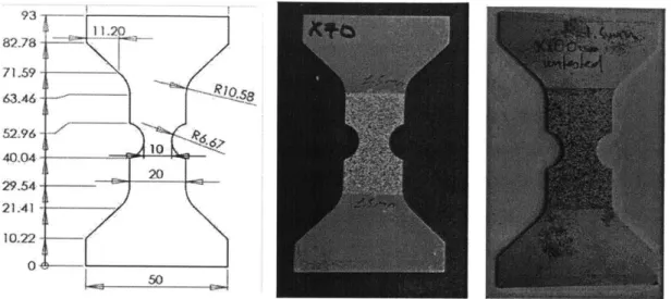
4-25 Blueprints of flat specimens with notch R = 6.67mm and dyed
4-26 Blueprints of flat specimens with notch R = 6.67mm and dyed
speci-mens used for API X70 and X100. . . . . 130
4-27 Blueprints of disks for the punch experiments and dyed specimens used
for API X70 and X100. . . . . 130
4-28 MTS uniaxial tensile wedge grips (left), MTS circular grips and die used for punch testing (right). . . . . 131
4-29 Schematic graph of the notched round bar specimens... . . . . 132
4-30 Flat tensile specimens with central hole finite element model. Mesh of model (left), boundary condition and loading (right). . . . . 135
4-31 Frames of the simulation of experimental procedure of flat tensile spec-imens with central hole. . . . . 136
4-32 Notched R6.67 tensile specimen finite element model. Modeling 1/8th of specimen (left), boundary condition and loading (right) . . . . 137
4-33 Frames of the simulation of experimental procedure of flat tensile
spec-imens with notch R6.67. . . . 137
4-34 Notched Circular disk specimens finite element model. Geometrical configuration (up-left), frames of the simulation of experimental pro-cedure (rest). . . . . 138
4-35 Butterfly specimens finite element model. Modeling of the gauge area
(left), mesh of model (right). . . . 138
4-36 Butterfly specimens finite element model. FEM results for tensile (left column) and shear (right column) butterfly specimens. . . . . 138
4-37 Comparison of experimental and numerical results for the central hole
specimen made of API X70. . . . . 139
4-38 Comparison of experimental and numerical results for the central hole
specimen made of API X100. . . . . 140
4-39 Comparison of experimental and numerical results for the central hole
specimen made of API X70. . . . . 141
4-40 Comparison of experimental and numerical results for the central hole
4-41 Comparison of experimental and numerical results for the punch spec-imen simulating bi-axial stress of state made of API X70. . . . . 142 4-42 Comparison of experimental and numerical results for the round notched
specimen, R=0.2, 0.5 and 1.0 simulating axi-symmetric conditions
made of API X70. . . . . 143
4-43 Comparison of experimental and numerical results for the round notched specimen, R=0.2, 0.5 and 1.0 simulating axi-symmetric conditions
made of API X100. . . . . 144
4-44 Experimental and numerical tested specimens for API X70. . . . . 144 4-45 Experimental and numerical tested specimens for API X100. . . . . . 145 4-46 History of stress triaxiality as a function of equivalent strain at the
location of failure initiation for X70 from numerical simulations of flat tests (strain shown in percentages). . . . . 145 4-47 History of stress triaxiality as a function of equivalent strain at the
location of failure initiation for X100 from numerical simulations of flat tests (strain shown in percentages). . . . . 146 4-48 Geometry of additional round X70 and X100 specimens. . . . . 147 4-49 History of stress triaxiality as a function of equivalent strain at the
lo-cation of failure initiation for X70 from numerical simulations of round tests (strain shown in percentages). . . . . 148 4-50 History of stress triaxiality as a function of equivalent strain at the
location of failure initiation for X100 from numerical simulations of round tests (strain shown in percentages). . . . . 149
4-51 3D Fracture locus for X70 . . . . 150 4-52 3D Fracture locus for X100 . . . . 150
4-53 Difference in mesh-size dependence on plastic equivalent strain to
frac-ture, q and 0 between API X70 and TRIP780. . . . . 151
4-54 Five hypothetical materials with different values for the hardening ex-ponent . . . . . 152
4-55 Dependence of hardening exponent on thickness to fracture for API
X70 and two additional material variations, n = 0.01 and n = 0.2. . . 152 5-1 SENT specimen sketch with pin loading applied at the ends of the
specim ens. . . . . 160 5-2 Time evolution of cracked surface normalized with respect to the Amax
for time step 9 (left), ts = 19 (middle) and ts = 23 (right). . . . . 161
5-3 Sketch demonstration of Ama, and Aave for the time step ts = 23. . . 162
5-4 Comparison of FE results with experimental data predicting the initial crack growth rate. . . . . 164
5-5 Initial crack growth of SENT specimens of API X100. . . . 165
5-6 Predicted crack propagation of SENT specimen until final separation
of A PI X 100. . . . 166
5-7 Comparison between numerically predicted initial crack growth and
experimental data for API X100. . . . 167
5-8 Schematic representation the main geometric features of a pressurized pipe with open ends. . . . . 172 5-9 Schematic representation the main geometric features of a pressurized
pipe with closed ends. . . . . 173 5-10 FEM models for the three different thickness cases, t = 0.6" (left),
t = 0.4" (middle) and t = 0.25" (right). . . . . 175
5-11 FEM bottom-up mesh and indication of element deletion for the
initi-ation of damage localiziniti-ation, simulating pre-existing defect. . . . . 176 5-12 Localization of damage initiation of yield in the defect region
demon-strated in the FEM simulation in terms of von Mises stress for Case
1... ... 177
5-13 Localization of damage and crack initiation in the defect region
demon-strated in the FEM simulation in terms of von Mises stress for Case
5-14 Localization of damage initiation of yield in the defect region demon-strated in the FEM simulation in terms of the damage factor for Case
2... ... 179
5-15 Effect of material and thickness on the bursting pressure of a pipe. . . 180 5-16 Difference in the safety factor evaluation between consideration of
thin-and thick-walled pipes for X70 thin-and X100. . . . . 181
5-17 Difference between analytic yield pressure for thick pipes with closed
ends and FEM predicted bursting pressure for three cases of API X70
(C ases 1, 3, 5). . . . . 182
5-18 Difference between analytic yield pressure for thick pipes with closed
ends and FEM predicted bursting pressure for three cases of API X100
(Cases 2, 4, 6). . . . . 183
5-19 Difference between analytic yield pressure for thick pipes with closed
ends and FEM predicted bursting pressure for six cases transitioning
from of API X70 to X100. . . . . 184
5-20 Power law fitting of the isotropic strain hardening behavior for TRIP690
and the concept of the energy equivalent flow stress [9]. . . . . 185 5-21 3-D fracture locus in the space of the equivalent strain to fracture,
stress triaxiality and Lode angle parameter for TRIP 690. . . . . 186 5-22 Initial configuration of the system of concentric pipes and shear ram
blades and the solid element discretization of the system. . . . . 188 5-23 Three stages of the crushing/cutting process shown with removed
cut-ting blades. Touching between the deformed outer pipe and un-deformed inner pipe is the starting point of stage two (orange area). Both pipes are then crushed together until complete flattening occurs. . . . . 189
5-24 At the last stage of the crushing proceed both tube cross sections are completely flattened by wedge type of cutting blades. . . . . 190 5-25 Onset of the cutting process with both pipes being completely locally
5-26 The distribution of equivalent plastic strain along the width of the
cross section (taken from [82]). . . . . 191 5-27 Analytical solution of the crushing/cutting process of the pipe
super-posed on the numerical solution. . . . . 193 5-28 History of shearing force and three stages of the cutting process. . . . 193 5-29 Triaxiality vs. equivalent strain to fracture for Point C (outer riser
pipe) and D (inner drill pipe). . . . . 194
5-30 Geometrical configuration of the bending numerical simulation model. 197 5-31 Finite element model mesh of the riser/ drill system with fine mesh
size prescribed in Area 1 and coarse used in Area 2. . . . . 198 5-32 Progression of bending of the system of riser/drill and localization of
dam age. . . . . 199
5-33 History of symmetry plane cross-section up until the onset of fracture. 199
5-34 On the left: Picture taken from the riser leak location of the Deepwater Horizon platform by underwater ROV. On the right: Comparison of failure location predicted by the Finite Element simulation with the damaged Deep Horizon installation. . . . . 200
5-35 Location of failure positions, Point A and B situated on the symmetry
plane of the bend pipe. . . . . 201
5-36 Tension dominated history of triaxiality at Point A, as a function of
equivalent strain. . . . . 202
6-1 Weight reduction trend between pipelines made from different API grades taken from [10]. . . . . 211
6-2 FEM models for the three different thickness cases, t = 0.6" (left),
t = 0.4" (middle) and t = 0.25" (right). . . . . 213
6-3 Evaluating the thickness reduction between X70 and X100 taking into account the full material characterization of both API grades. . . . . 214 6-4 Difference in the safety factor evaluation between consideration of
6-5 Difference between analytic yield pressure for thick pipes with closed ends and FEM predicted bursting pressure for six cases transitioning
from of API X70 to X100. . . . . 216 6-6 CAPEX breakdown for pipelines. . . . . 217
6-7 Effect of price ratio between X70 and X100 to the material cost. . 219 6-8 Effect of price ratio between X70 and X100 to the material cost. . 221
6-9 Expected revenue cash flows of a pipeline. . . . . 222
6-10 Historic data of oil price market between 1946 and 2012. . . . . 223 6-11 Trend towards AHSS observed in the automotive industry. . . . . 224
6-12 Common trend towards AHSS observed in the O&G and automotive
List of Tables
1.1 Comparison of Energy Intensiveness between different means of oil and gas transportation. . . . . 44 4.1 Number and thickness per type of specimen for X70 API grade . . . . 104 4.2 Number and thickness per type of specimen for X100 API grade . . . 104
4.3 Chemical analysis of X70 . . . . 111 4.4 Chemical analysis of X100 . . . . 112
4.5 Pre-necking plasticity parameters calibrated for X70 and X100 grades. 119 4.6 Lankford coefficients and yield stress ratios for X70 and X100. . . . . 124 4.7 Fracture constant for X70 and X100. . . . . 151 5.1 Finite Element Model Simulation Cases . . . . 174
5.2 Fracture parameters for TRIP 690. . . . . 186 5.3 Geometry of the riser-drill pipe system. . . . . 187 6.1 US onshore gas pipeline estimates for 2007, taken from [53] . . . . 205 6.2 US offshore gas pipeline estimates for 2007, taken from [53] . . . . 205 6.3 Finite Element Model Simulation Cases . . . . 213
6.4 Results from sensitivity analysis of material price to the cost change between X70 and X100 pipelines of the same safety. . . . . 218 6.5 The effect of the discount rate in the Cost NPV . . . . 220
Abbreviations
ABS American Bureau of Shipping
AHSS Advanced High strength Steel A1203 Aluminium Oxides
API American Petroleum Institute
BG British Gas
BP British Petroleum BV Bureau Veritas
CAPEX Capital Expenditures
CaS Calcium Sulphide
CBA Cost Benefit Analysis CCS China Classification Society CDF Crack Driving Force
ClassNK Nippon Kaiji Kyokai
COD Crack Opening Displacement
CRES Center for Reliable Energy Systems
CSM Centro Sviluppo Materiali CT Compact Tension
CTOA Crack Tip Opening Angle
CTOD Crack Tip Opening Displacement CVN Charpy V Notch Tests
DIC Digital Image Correlation
DnV Det Norkse Veritas
DWTT Drop Weight Tear Tests
EAW Electric Arc Welding
ECSC European Coal and Steel Community EMSA European Maritime Safety Agency
EPRG European Pipeline Research Group ERW Electric Resistance Welding
FAD failure assessment diagram FE Finite Element
FEM Finite Element Modeling
GL Germanischer Lloyd GMA Gas Metal Arc
GoMOS Gulf of Mexico Oil Spill
GTN Gurson-Tvergaard-Needleman model
HAZ Heat Affected Zone
High Pressure/ High Temperature HP/HT
HSAW Helical Submerged Arc Welded
IACS International Association of Classification Societies ICL Impact and Crashworthiness Lab
ISOPE International Society of Ocean (Offshore) and Polar Engineering JIP Joint Industrial Project
KR Korean Register of Shipping LOM Light Optical Microscopy LR Lloyd's Register
LSAW Longitudinal Submerged Arc Welded MC Mohr-Coulomb
MMC Modified Mohr-Coulomb NK Nippon Kaiji Kyokai (ClassNK)
NPV Present Value
O&G Oil and Gas
OD Outside Diameter
OMAE International Conference on Ocean, Offshore and Arctic Engineering OPEC Organization of the Petroleum Exporting Countries
R&D Research and Development R-curve Resistance curve
RINA Registro Italiano Navale ROV Remotely Operated Vehicles
ROW Right of Way
RS Russian Maritime Register of Shipping
SAW Submerged Arc Welded
SBD Strain-Based Design
SEM Scanning Electron Microscope
SENB Single Edge Notched under Bending SENT Single Edge Notched under Tension SOLAS Safety Of Life at Sea
TiN Titanium Nitride
Chapter 1
Introduction
This chapter starts with setting the background of the current thesis, highlighting the transition from fracture technology for the automotive industry towards fracture for the oil and gas industry. More importantly, the focus of this study will be the transition from investigation of plasticity and fracture behavior of metal sheets to thick-walled pipes. The next step will be stating the hypothesis of the applicability of the Modified Mohr-Coulomb (MMC) model for the structural evaluation of pipelines and risers. The significance of this research area will be presented including the motivation and contribution to both academic and real world problems. The correct and reliable safety assessment of pipes and risers for complex loading scenarios lies in the extension of a powerful fracture technology to a new set of problems. Finally, the financial implications of comparing high and low strength API grades for both existing and future newbuildings infrastructure for cost assessment is presented for two specific pipeline cases. Finally, the outline of the thesis is presented, including
the proof of the hypothesis and the benefits stemming from it.
1.1
Setting the Background for the Research
Pose question that the thesis will answer!
Over the past 10 years the Impact and Crashworthiness Lab (ICL) at MIT has developed a complete fracture predictive technology for steel sheets under the
spon-sorship of the worldwide steel and automotive industries. This technology has now reached a stage of full maturity that allows for the reliable and high accuracy predic-tion of any sheet metal forming and crashworthiness applicapredic-tion. This technology has been developed and evaluated as an important predictive tool for both the automo-tive and steel industries. The applicability of this technology remains to be evaluated, however, for cases of thick-walled structures, where the stress state conditions signifi-cantly vary through the thickness and also throughout the loading process. This new set of problems remains to be studied, so that the MIT fracture predictive technol-ogy can be applied to new fields of engineering with stress states that significantly depart from the plane stress state region. Also, this modern approach is required to be compared to the standard fracture mechanics methodologies currently used for the assessment of thick tubular components. The main objective of the current thesis originally aimed to test the hypothesis of applying the MIT technology to general cases of fracture prediction and strain based design of pipelines and risers. However, due to inherent differences in the setting of the problem in the case of heavy-walled tubular components, primary research focused on extending the applicability of the MIT fracture technology to cover a much larger range of stress states [58]. The most important difference between sheets and thick tubes lies in the fact that in plasticity and fracture characterization of steel sheets, the stress state is close to plane stress, which simplifies the underlying equations, both for the description of the plasticity and fracture behavior of the material. At the same time, in the case of heavy-walled pipes, the material properties and stress state during operation and failure depends largely on the wall thickness and loading setting. Another important difference is the fact that in the current study, the material is characterized as an end product, rendering the manufacturing process an important factor that affects immensely the plasticity, anisotropy and fracture behavior of the final metal structure of interest.
Different industries focus on different engineering and design parameters. In previ-ous research, ICL was interested in understanding how the originally produced sheet would sustain the manufacturing process loading during sheet metal-forming and also the dynamic loading during accidental impact. In the current line of work, the main
interest is to understand how the manufacturing process affects the safety and life expectancy of the final product. In the Oil and Gas (O&G) industry, pipelines and risers have a special value in the industry's supply chain. The safe extraction, produc-tion and transportaproduc-tion of oil and gas greatly depends on these critical components, affecting managerial decisions and also the oil and gas market itself. There are ex-amples of safety breaches of pipelines and risers that led to disturbance of oil and gas flow that subsequently affected also the financial market. For example, the recent Gulf of Mexico, Deepwater Horizon accident, led to a significant decrease of O&G companies' market value. It was estimated by Bloomberg in 2010 in that companies that were associated with the Gulf of Mexico Oil Spill (GoMOS) lost $(US)95bn (see
Fig. 1-1). The effect of failure of pipelines and risers is significant and additional work is required to fully understand how material properties and loading may lead to a structural collapse and the subsequent event of leak. The result of the intense in-depth research conducted in 2011 by National Commission report on the BP Deep-water Horizon Oil Spill and Offshore Drilling, resulted in the following statement: "Deepwater energy exploration and production, particularly at the frontiers of expe-rience, involve risks for which neither industry nor government has been adequately prepared, but for which they can and must be prepared in the future."
Therefore, understanding and reliably reconstructing extreme case scenarios and de-signing the correct procedures for minimizing the environmental effect due to catas-trophic events has not only a pragmatic environmental but also financial and economic effect. The current study explores in depth the technical part and touches upon the financial implications of responsible and safe engineering, so that technological ad-vances may lead to large-scale adoption of oil and gas as a safe energy source even when explored and produced in highly dangerous locations.
Oil
Spill's Da age Co es in Many
Forms.-c
spm lhave lostabout $90 billion in comibined market value since the disaster.
do' w in RUS Fguesn
ftroughMa24.
Figure 1-1: Deepwater Horizon accident negative effect on market value of companies associated with the oil spill [84].
95 -94 93 -92 -91 . 90 - FACTS (+700 kbd vs. 2007) 89 ~ 88 -IEA (+300kbd) 87 -84 80 2007 2008 2009. 95 Precrisis / 92 Modeae * 88 Severe 86 Verysevere :2 2010 2011 2012
*Cndeo at the wet head; renginseinc luededindemand
Source:lEA 0#MarketRepor, December 2008;Bemstein, Odober 2008; FACTS, Odob 2008;
-isy
Globa InsUhe Gobal Eneny Dmad Model2009Figure 1-2: Oil demand predictions for different market projection scenarios ranging from conservative to optimistic [28].
.e
I I
Figure 1-3: Exploration and production trend towards deep and ultra deepwater territories [68].
All the above are combined with a unique set of events that lead to an increased
de-mand for energy resources (see Fig. 1-2), similar as the rise of new markets like China and India. The oil and gas industry is riding the wave of surging demand in which the risers and key pipelines are reshaping the global economy in terms of exploration and transportation of oil and gas. The structural integrity of those components is therefore an important parameter that is required to be thoroughly investigated with the state of the art technical tools such as the MIT fracture predictive technology. That results in a massive expansion of oil and gas demand forcing O&G companies to move into more hostile environment-located reservoirs (ultra deep water and arctic) to match the existing supply [36] as it is shown in Fig. 1-3.
It is also important to mention that it is predicted by the US Energy Information Administration's World Energy Outlook that fossil fuels will remain the primary sources of energy, meeting more than 90% of the increase in future energy demand that is assessed to rise by about 1.6% per year, from 75 millions of barrels of oil per day (mb/d) in 2000, to 120 mb/d in 2030. As far as the natural gas consumption demand is concerned, it is expected to double between now and 2030. In this highly lucrative
business, safety poses a barrier and a competitive advantage to oil companies. Data from previous years show that companies like Exxon Mobil (the world-leading oil company that announced in January 2006 profits of $US36 billion) and Shell Oil (that announced a record profit for a British company of $US23 billion, in February 2006) are more open to new technologies that will provide the competitive edge and thus the necessary licenses to explore even more demanding fields. The growth in energy demand was and will continue in the future to be supported by extensive expansion of the pipeline infrastructure. Over approximately the last 50 years, the pipeline network has grown by a factor of 10 and is expected to be up by 7% per year over the next 15 years. This means over 8000 km/yr of pipeline being built in the USA alone, at a cost of $(US)8 billion/yr. The structural integrity of pipelines becomes very important especially taking into account that the main causes of pipeline failure in the USA is accidental loading (external force) leading to environmental catastrophes and casualties, as shown in Fig. 1-4.
Operquip. ConstrMat. Error Defect 10%- 9% Failure at pipelweld 12% Liquid Gas
Figure 1-4: Percentage breakdown of main failure causes the US pipeline infrastruc-ture [52].
Pipes are designed to withstand multiple operating, installation, environmental and accidental loads. An important and traditional design parameter is the internal
pressure that is related to the circumferential (hoop) stress, uh"o defined in Eq. (1.1).
Ohoop ~ pD ~ ayield
(1.1)
where p is the internal pressure, t is the thickness of the pipe, a is the design safety factor and oyield is the yield strength of the base material.
However, the above-mentioned formula leads to over-engineered pipes taking into account only the plasticity information of the base material. As the demands of safe pipes increase and the loading conditions become more extreme, new models are needed that take into account the detailed mechanical characteristic of the pipe material. Other industries, like the automotive, were forced to move faster towards modern approaches for economic reasons that required the decrease of the vehicle weight that is easily translated into gasoline consumption per mile traversed. In the case of the O&G industry, the improvement of the understanding and modeling of the material behavior is driven by the increasing requirements for safer and more economic design in extreme environments, like the arctic and ultra-deep underwater locations. This industry is notorious for its reluctance towards new methods and its support to over-engineering as the best alternative to a complex and modern approach. Although change is not welcomed by O&G community, however, it is required especially after the GoMOS effect in the offshore drilling legislation and in the market value of related oil companies. There is one of the driving forces towards achieving not only the structural integrity but also the economic design and reduction of over-engineering. Also, as new grades of steel continue to emerge, it is important to have a reliable fracture predictive tool that allows for a comparison and assists the designing process both from a technical and economical point of view.
1.2
Pipelines and Risers
The current thesis is primarily concerned with the investigation of the structural integrity of pipelines and risers. In the offshore exploration, production and
trans-portation of oil and gas, pipes play a very significant role. Pipes are used in offshore and onshore installation both vertically, connecting the production facility with the reservoir and also horizontally, connecting remote wells to the location of processing or to the transportation hub. Pipelines are the most effective means of transportation for oil and gas. They offer a vast array of reasons favoring them against others means like transportation by tankers, trucks, rail etc. The main advantages of pipeline use for transportation of oil and gas are both economic and social. More specifically, pipelines offer a large throughput over extended hostile territories with low main-tenance costs at a fraction of the cost of transportation compared to other means previously mentioned. They also offer the second best value proposition for trans-portation of oil and gas, as it shown in Fig. 1-5.
Tanker
Pipeline
Barge
Rail
Truck
0
10
20
30
40
50
Cents
/ Barrel-mile
60
70
80
Figure 1-5: Comparison of transportation cost between major logistics methods for petroleum.
Table 1.1: Comparison of Energy Intensiveness between different means of oil and gas transportation. Airplane 37,000 Truck 2300 Railroad 680 Waterway/Barge 540 Oil Pipeline 450
Pipelines have also very low energy intensity, that is defined as the energy con-sumed in transporting a unit weight of cargo over unit distance (such as Btu per tonne mile), see Table. 1.1. It is finally important to mention that the safe opera-tion of pipelines is environmental friendly. However, when their safety is breached, the pollution affects greatly the surrounding environment. Risers on the other hand connect the reservoir that is located in the bottom of the ocean floor to the platform without contaminating the surrounding environment. According the location of the well, the depth, the ocean wave profile in the specific location and the well charac-teristics, risers are designed appropriately to connect the production site to hub for further transport or immediate processing. The length of risers are not usually so
extensive as in the case of pipelines.
The manufacturing process for pipelines and risers is the same. Pipelines and risers can be referred to as tubes or tubular components. There are mainly two types of tubes used extensively in the transportation of oil and gas, classified based on the method of pipe manufacturing.
" Seamless pipes
- Pilger mill process
- Plug mill process
- Push mill process
- Continuous mandrel mill process
- Hot pressure welding
- Electric resistance welding
- Electric arc welding
The seamless pipe manufacturing process starts with the heating of the solid billets using the Mannesmann process. Depending on the final diameter and thickness, one of the four following processes one of the following process is used i) continuous casting of round billets, the pug mill, the mandrell mill and the pilger mill. As far as the welded pipes are concerned, there are many categorizations based on the i) forming process, ii) the welding process, iii) the nomenclature, iv) the type of weld and v) the size range.
The manufacturing process plays a critical role in the mechanical characteris-tics of the end-product. Therefore, in the long run the industry should undertake a comprehensive project of transferring the data and the numerical analysis from the manufacturing phase to the final operating conditions of the pipe installation. The situation facing the O&G industry is somewhat similar to the one studied by and on behalf of the steel and the automotive industries. Computational models were de-veloped to monitor the evolution of the stress and strain tensors during the forming process of components from sheets. The end data of the above-mentioned simula-tions was the input in the finite element analysis for the prediction of the crashing process. The history of deformation caused during the manufacturing phase of tubes is not included directly in the analysis, but rather indirectly through analyzing the mechanical properties of the pipe material after it has underwent the manufacturing process.
1.3
Structural Integrity of Pipelines and Risers
Offshore pipelines and risers installed in the ultra-deep water depth nowadays are exposed to high external pressure and temperatures. The large plastic deformations may arise during pipe installation (reeling, S-lay, J-lay), under operational conditions
such as free-spans due to uneven seabed topography and wave motion causing sway movement or due to temperature variations leading to local failure due to extreme localized strains. This work focuses on the base material analysis as the first main step illustrating the efficacy and importance of this modern fracture approach for pipe structural integrity assessment. In the recent years, the strain-based approach has been introduced mainly for pipelines. This approach is more appropriate for dealing with global large plastic deformations when compared to the traditional stress-based approaches. Assuming that the pre-service defects resulting from manufacturing, in-stallation (e.g. girth weld defects) and operational process cannot be avoided, these approaches have been extended to allow for flaw assessment. The procedure used by the industry for the assessment of flawed structures is based on the Failure Assessment Diagram (FAD) representing the limit curve of toughness and strength controlled fail-ure. It is implemented in standards and recommended practice such as [31] , [19],
[47] and [29]. In case of strain-based flaw assessment, the strain capacity equations (e.g. [33] and UGent equations [38] and [42] and ExxonMobil procedures [59] have been developed to quantify design and allowable strains in dependence of different geometry (pipe diameter, wall thickness, flaw size, etc.) and material parameters (ultimate tensile strength UTS, Y/T ratio, ultimate elongation UEL, weld strength mismatch, toughness, etc.). If the material shows ductile tearing in the stable way prior to final fracture, the fracture toughness is considered in terms of failure Resis-tance curve (R-curve) instead of single threshold values (Jmat or CTODmat). The resistance curves depend on both the material properties and on the crack tip con-straint for the given geometry and loading situation. As shown in [23] they can be normalized by the constraint parameter T-stress. For the derivation of failure crite-rion, the onset of the unstable crack growth is identified using traditional tangency criterion which requires comparison of Crack Driving Force (CDF) and R-curves. Since the experimental determination of the R-curves for full-scale tests can be very time- and cost-intensive, especially in the view of parametric studies for different pipe geometry, numerous computational fracture models have been developed within the finite element framework aiming to characterize ductile fracture propagation of steel
materials for small and full-scale tests. There are two groups of models, fracture me-chanics and damage meme-chanics based models. A typical example of the former is the mapping approach which interpolates ductile tearing between results of several sim-ulations with fixed but different crack sizes [50]. There are several major limitations of the fracture toughness approach. First, it requires the presence of initial cracks and it will not work to predict initiation of fracture in crack-free bodies. Secondly, it only provides information of initial crack growth, thus fails to predict post-failure behavior of a given component all the way to a complete separation. Thirdly, no constraint effect is considered explicitly, but has to be included via constraint nor-malized R-curve. Fourthly, no direction of the crack propagation including crack path deviation can be predicted without a user-defined criterion. Finally and most importantly, the approach is restricted to the stress states at the crack tip generating merely Mode I fracture. By contrast, damage mechanics theory is able to describe crack initiation and propagation by allowing the damage evolution to take into ac-count both the influence of local stress and strain variables. Hence, ductile crack propagation can be fully represented within a single simulation. One of these models is Gurson-Tvergaard-Needleman (GTN) model [48], [78]; and [79] and its subsequent modifications. The GTN model and its extensions have removed all above mentioned limitation of the fracture mechanics based models but introduced several new issues. The micromechanics-based GTN model describes the failure mechanism as a sequence of void nucleation, growth and coalescence. Recent modifications of GTN, e.g. to ac-count for shear-stress dominated fracture [56]; [14]; [16] lead to an increase of the additional phenomenological parameters and therefore lost its original appeal. The number of free parameters of the shear modified GTN model has increased to 13 from the original 7 in the GTN model. This creates difficulties in the calibration procedure which should be an integral part of all fracture modeling. Several dispos-able parameters in the GTN model are responsible for the coupling of fracture with plasticity. Recently [41] showed that this large set of parameters is not necessary for achieving a good correlation in the plastic and fracture range for low triaxiality levels. Another finding was that the GTN model and its derivative cannot predict fracture
in the combined regime of shear and compression loading. The next step in the de-velopment of fracture technology is the Modified Mohr-Coulomb model that is the methodology proposed in this thesis. This is a phenomenological but physics-inspired model. It requires the calibration of three free parameters and it is applicable to the whole spectrum of stress states from tension and tension/shear to pure shear, all the way to shear and compression. It has been proven for metal sheet applications and it is proposed for the prediction of failure for pipeline and riser applications. The two parameters are defining the classical Mohr-Coulomb fracture model and the third parameter is responsible for the local shape of the yield condition, introduced by [26]. It was successfully applied for the prediction of ductile fracture initiation and
prop-agation in advanced high-strength sheet and low-strength aluminum materials [24]. This extended model describes the equivalent strain to fracture depending on stress triaxiality and Lode angle that is the normalized third invariant of deviatoric stress tensor. To derive the three-dimensional fracture locus, it is necessary to calibrate only three model parameters by at least the same number of experiments. The suitability of the MMC model to characterize ductile fracture has been demonstrated in many publications, primary for the ranges of low stress triaxiality (,q < 2/3) see (e.g. [24],
[41]). On the other hand, there is little information about the accuracy of the model prediction for the high triaxiality range, i > 1.0, which is very important for analysis
of cracked structures. Recent results on the case on API X100 were given in [62] val-idated by compact specimen experimental and numerical results. The present thesis is explaining in detail the extension of the applicability of the MMC model to the range of high stress triaxiality. This is the area so far dominated almost exclusively
by the fracture toughness method and the GTN approach.
1.4
Major Pipeline and Riser Problems
It is important to note that the O&G community is facing a number of important challenges that command for modern fracture prediction methods for the safe design and operation of pipes. Independent of the specifics of the application, pressing
is-sues call for a new method to address existing and future development scenarios and challenges. Ranging from Deep to Ultra Deep Water, pipeline installations down to three kilometers or more are required to address the expansion of subsea system de-velopment. The material properties along with external hydrostatic pressure which becomes the main design parameter, the geometric imperfections and the complex loading conditions exerted by neighboring structural components significantly affect the structural integrity of the pipe. That combined with hostile environmental and operational loading conditions create a dangerous mix. Risers in the same environ-ment face the same challenges as pipelines, with the addition of severe cyclic loading due to platform sway movements consequent to wave, wind, currents and tidal load-ing and also due to vortex sheddload-ing induced vibrations directly actload-ing on the riser line due to currents. In this study we will focus on monotonic loading and consider that cyclic loading and additional loading component can be studied independently. High Pressure combined with High Temperature (HP/HT) for cases of exposed pipes into the sea bottom or buried are additional application that need to be investigated. Thermal expansion and lateral bending deformation randomly located or at specific locations along the pipeline route and vertical weight and lateral movement of the superstructure connecting the well to the free-surface are more examples of complex problems that need to be addressed by the community. Finally, abrupt dislocation of parts of the pipe, such as in gauging cases in the arctic environment and ground movement due to seismic excitation leading to large local strains, demand a new methodology that focuses on strain based design. All the above mentioned issues are combined with the continually aging infrastructure for exploration, production and transportation of fossil fuels and the continued evolution and development of new grades of steel toward Advanced High Strength Steel (AHSS) grades. In the following sections more information of how these two aspects create the appropri-ate environment for research focusing in the structural integrity assessment of thick tubular components will be presented.
1.4.1
Aging of Oil & Gas Infrastructure
One of the most important problems facing the O&G industry, is the fact that the pipeline and marine riser infrastructure is reaching and exceeding their assumed de-sign life span. Over 50% of the USA oil and gas pipeline system (1M km) is over 40 years and 20% of Russians oil and gas system is nearing the end of its design life ac-cording to the Mineral Management Service database. The correct assessment of the structural integrity and the remaining life of this infrastructure is important in order to tactically replace older, or more damaged components first and cause the minimum amount of interruptions of flow due to failure events. After the world's pipe infras-tructure reaches their life expectancy, the oil and gas community will have to face the challenge of replacement. As environmentally related legislation becomes more stringent, it is important to develop tools that reliably assess any additional opera-tional life of an existing asset and that they are fit for purpose. Therefore, a proactive integrity management of onshore and offshore pipe assets and a re-evaluation of their fitness-for-purpose is essential, making sure that at the end of their predicted oper-ational life there exist proactive measures to pick up the demand for transportation for the next 50 years. In about 15 years, more that half of the existing infrastructure will be at the end of its design life Therefore, care for our aging assets is a major engineering challenge and structural integrity assessments will be a key tool in the near future.
1.4.2
Trend towards API AHSS Grades of Steel
Among many engineering problems involving ductile fracture, the heavy-wall seamless pipelines, risers and drilling pipes present a class of their own. Deep and ultra-deep offshore exploration and productions pose many challenges to the O&G industry.
Of particular interest are the choice of the right material and the determination of
structural integrity under normal and accidental loading. A grim reminder of the potential hazards is the recent accident of the BP Deepwater Horizon drill platform. There has been a debate within the O&G industry on the right choice of material
![Figure 1-1: Deepwater Horizon accident negative effect on market value of companies associated with the oil spill [84].](https://thumb-eu.123doks.com/thumbv2/123doknet/14753753.581438/39.918.199.695.128.406/figure-deepwater-horizon-accident-negative-effect-companies-associated.webp)
![Figure 1-3: Exploration and production trend towards deep and ultra deepwater territories [68].](https://thumb-eu.123doks.com/thumbv2/123doknet/14753753.581438/40.918.202.693.134.465/figure-exploration-production-trend-towards-ultra-deepwater-territories.webp)
![Figure 2-5: Schematic representation of the continuous push bench manufacturing process [64].](https://thumb-eu.123doks.com/thumbv2/123doknet/14753753.581438/61.918.144.738.127.552/figure-schematic-representation-continuous-push-bench-manufacturing-process.webp)