Publisher’s version / Version de l'éditeur:
Vous avez des questions? Nous pouvons vous aider. Pour communiquer directement avec un auteur, consultez la
première page de la revue dans laquelle son article a été publié afin de trouver ses coordonnées. Si vous n’arrivez pas à les repérer, communiquez avec nous à [email protected].
Questions? Contact the NRC Publications Archive team at
[email protected]. If you wish to email the authors directly, please see the first page of the publication for their contact information.
https://publications-cnrc.canada.ca/fra/droits
L’accès à ce site Web et l’utilisation de son contenu sont assujettis aux conditions présentées dans le site LISEZ CES CONDITIONS ATTENTIVEMENT AVANT D’UTILISER CE SITE WEB.
Building Research Note, 1984-08
READ THESE TERMS AND CONDITIONS CAREFULLY BEFORE USING THIS WEBSITE.
https://nrc-publications.canada.ca/eng/copyright
NRC Publications Archive Record / Notice des Archives des publications du CNRC : https://nrc-publications.canada.ca/eng/view/object/?id=28258818-acba-47a7-a40c-69ab43384f16 https://publications-cnrc.canada.ca/fra/voir/objet/?id=28258818-acba-47a7-a40c-69ab43384f16
NRC Publications Archive
Archives des publications du CNRC
This publication could be one of several versions: author’s original, accepted manuscript or the publisher’s version. / La version de cette publication peut être l’une des suivantes : la version prépublication de l’auteur, la version acceptée du manuscrit ou la version de l’éditeur.
For the publisher’s version, please access the DOI link below./ Pour consulter la version de l’éditeur, utilisez le lien DOI ci-dessous.
https://doi.org/10.4224/40000498
Access and use of this website and the material on it are subject to the Terms and Conditions set forth at
Fire tests on insulated sheet steel walls Bardell, K. H.
BUILDING
RESEA
NOTE
FlFtE TESTS ON INSULATED SHEET STEEL WALLS
by
K.B. Bardell
FIRE TESTS ON I N S U T E D SHEET STEEL WALLS
bY K.H. Bardell
The National Building Code of h a d a (NBCC) requires that insulated
sheet steel w a l l s commnly used on the exterior of cormaercial and industrial
buildings have a fire resistance rating of h or more, In certain
aftuatims t h i s requlremnt may be waived f o r exterior walls located 1.2 m or further froin adjacent structures @BcC 3.2,3,9) (1). For such walls, the temperatures,
s,
on the unexpoeed face during a s p e c i f i e d time under f i r e test cmdi'tiona governs the required s p a t i a l separation.A
aeriea of ten emalle9cale f i r e t e s t s of insulated sheet-steel walls had previously been conducted (2) t o study t h e m 1 perfotmaace. The p r e a a treport describes the results of two full-8cale f i r e resistance tests
designed t o verify small-scale t e s t results and detsrmfne f i r e resistance
values and spatial separation requiremmts for insulated sheet-steel walls.
The results of a cavlty wall test are a l s o reported,
DESCRIPTION OF SPECIMENS
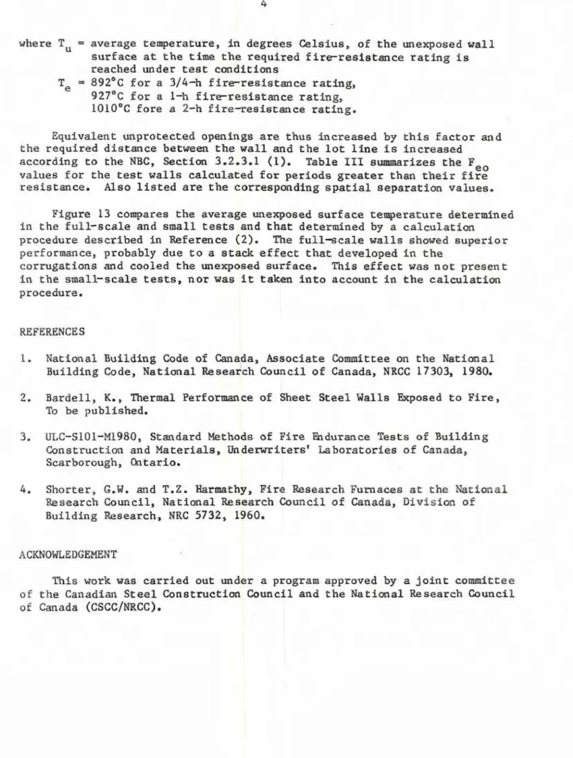
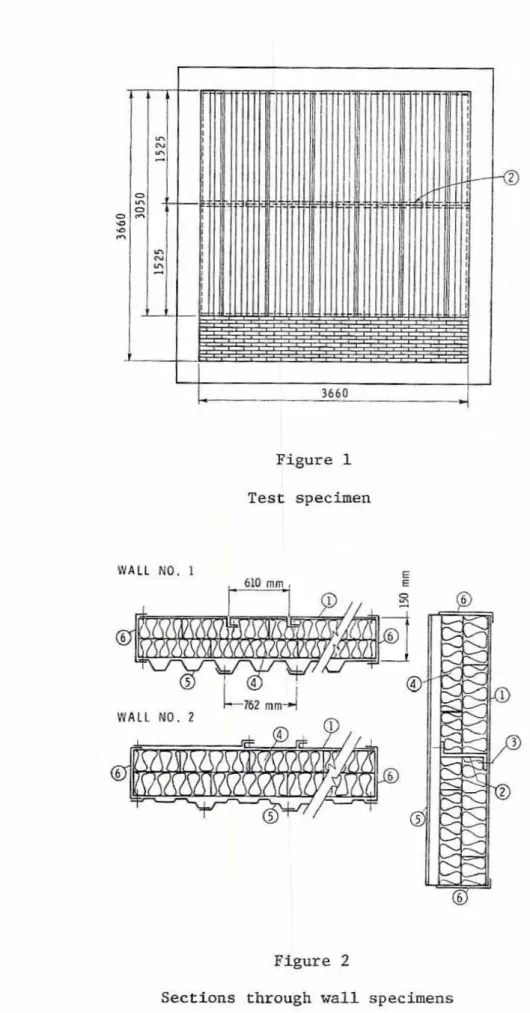
Details of the test specimens are shown in Figures I and 2 , i t e m
numbers below correspmding t o the part nmbers.
1, Steel liner sheet; 0.46
nrm
thick, 610 ~ l r m wide pauels; l i p - t y p e caulked vertical seam; #12 eheet m e t a l screws through the l i p at 300 mm u.c.;Test No. 1
-
lips h s i d e wall, T e s t No. 2-
lips outside wall.2. Sheet metal z-bars; 150 mm wide; screwed t o l l n e r at 300 m 0 . c ~ ; Test
No. 1
-
1.22 mm t h i c k , f i v e bars of 606 m m lengths and two bars of '303 mm length. There is a space of 4 arm between the bars (see Figure 1 item 2). T e s t No. 2-
1.91 mm t h i c k , m e cmtfnuous bar of 3630 mmlength.
3. Ceramic paper; 3.2 maa thick, glued to both e-bar flanges; Test
No. 1
-
1 layer, T e s t No. 2-
2 layers.4. Rock wool insulation; 128 kg m3 density; t w o layers of 75- t h i c k batts; 610 by 1220 mm square; vertical joints staggered.
5 . Exterior steel sheet; 0.46 ntm thfck, 762 mm wide painted panels; lap-
type vertical-j oint sheet metal screwed at 410 mm O.C. through the lap;
screwed t o z-bar a t 410 dmt 0.c.; Test No. 1
-
"V-beam" profile, %st6 . Sheet a t e e l channels; 1.52 ma thick, 150 mm wide; ecrewed t o l i n e r and exterior sheet st 310 mm a-c. top and battoa and 410 mm o.c, on sides;
ramset t o cmcrete restraining frame a t 410 mm o.c,
(The following items were not part of the t e s t specimen.)
7.
Reinforced concrete ~ e s t ~ a i o i n g frame,8. Red clay brtcks md mortar uaed as a filler between the frame (item
No. 7) and the t e a t specimen.
Wall caostructiwn was carried out by co-rcial sheet: steel erectors,
Figures 3 and 4 s h w the walls before t e s t .
TEST PILOCEDUllE
The specimens were subjected to fire test in accordance with UZC S101-
M1980 (3), following the prescribed t h e f u r n a c e temperature curve f a r s
period of 2 h. The furnace teraperature was masured by nine symmetrically distributed thermocouples enclosed in incanel tubee. The h o t junctim of each was placed 150 mm from the exposed surface of the specimen. Both
individual temperature at the nine p o i n t s in the furnace and the average of the nlne temperatures were recorded. The fuel input i n t o the furnace was automatically cmtrolled. A detailed description of the f i r e t e s t
f a c i l i t i e s of the National Besearch CMmcil is available (4).
The temperature of the ttnexposed surface of the specimens W a s measured
by nine f i x e d thermocouples and a roviPg one (Figure 5 ) . Numbers 3, 5, 6
and 8 plus the roving thermocouple =re placed in the valleys a£ the
corrugatims; the others were placed on the ridges. A l l w e r e covered w i t h
12- thick asbestos pads measuring 50 mm by 50 mm. The pads were smaller
than standard in order that they would fit in the corrugations.
In
Test No. 1 t h e roving thermocouple was fixed in a valley at z-bar l e v e l nearthermocouple 1 a t 1 h and remabed there f o r the duration af the test. h
Test No. 2 i t was in place from the begtming of the test, The lateral
deflectim of the specimen w a s measured at the wall centrepoint w l t h an LVDT (Ifnearly varying d l splacenmt trlmsducer).
OBSERVATIONS
Test No. 1
For the first 20 d n , smoke issued from the top of the corrugations on
the unexposed side, accompanied by flaming at t h e f h e a r seams on the
exposed side, indicating combustion of the organic l i n e r lip caulking. Steam continued t o issue from the top of t h e corrugations for the d u r a t i m of the test. The liner sheet underwent s f ~ i f i c a n t : defo-tim during the f i r s t 40 min, Including buckling and s e a m opening between screws (~igure 6 ) . A t I* h, 75- diam hot spots, Andicated by p a i n t charring on the unexposed face, appeared at a corrugation r i d g e near the t o p centreline and near the
z-bar screws. Ftom Figure 6 it is evident chat there was little or no
deterioraticm of the insulation near the unexposed surf ace nor of the
exterior sheet. The centreline of the wall deflected inward throughout t h e t e s t .
Test No, 2
Wall No. 2 behaved the same as wall No. 1 with the folloufng
exceptioas: the continuous z-bar bent in an s-shape at 1 h 10 min; a hot
spot developed at thermcwple Ho. 2, caused by opening of the l i n e r seam a t
t h i s locatia; the centreline of the w a l l deflected outward as t h e t e s t
began and returned toward the furnace near the end of the t e s t . Figure 7 shaws the w a l l after test.
The average furnace temperature, average-exposed surface temperature,
and temperatures of the nine fixed t h e m c o u p l e a and one rovtng one are given in Tables I and I1 and shown la Figures 8 a a d 9 f o r both testa. Deflections of the centrelhe are p l o t t e d in Figures 10 and 11.
Test No. 1
The f i r e resistance of the wall was 1 h, 40 min; failure was due to the fact that the termperature (measured by the roving thermocouple) on the
unexposed surface exceeded t h e allowable limit, 26
+
163 = 18g°C, accordingto ULC-S101 (3). The t e s t was terminated after 2 h. Test No. 2
The f i r e resistqnce af the wall was 1 h and 30 min; failure was due t o the fact that the temperature (measured by the roving thermocouple) on the
unexposed surf ace exceeded the- d l w a b l e limit. The test was terminated
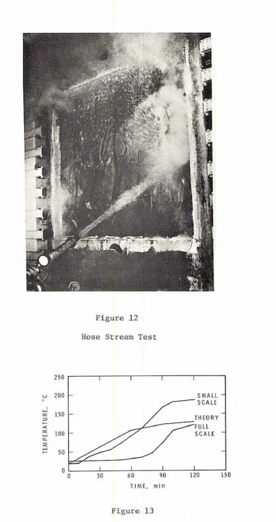
after 2 h. Immediately f a l h w i a g the t e s t s t h e furnace was opened and the
specimens were subjected t o a 180-8 Rose stream test l a which the water pressure was 205 kPa (Figure 12). The specimens s hawed n o further
deterioration as a reault of the hose stream test,
The N a t f u n a l M l l d i n g M e , s e c t i m 3 - 2 - 3 3 ( I ) , dictates the s p a t i a l
separatfam requiremts far walls that do not pass the insulation
requiremedlts of t h e fire resistance test but remain intact f o r a given fire
r e s i s e a ~ c e period. h equivalent opening factor,
so,
i s calculated for t h e w a l l at: the given period according to:(T,
+
273)'where TU = average temperature, in degrees Celslus, of the unexposed wall surface at the t i m e the required fireresistmce rating is
reached under t e s t c a d i t i o n s T
, = 8 9 2 ' ~ for a 314-h f ireresistmace rating, 927°C for a 1-h fireresiatrmce rattng,
10IO°C fare a 2-h Eire-resistance rating.
Equivalent unprotected openfngs are thus hcreased by this factor arld the required d i s t a n c e betwea the wall and the lot l i n e is increased
according t o the WBC, Sactim 3.2.3.1 (1). Table 111 stlgsriszes t h e
,
,
F
values for the test walls calculated for periods greater than their fire
resistmce. Also 11 sted are the correspmding s p a t i d aeperrarian values.
Figure 13 compares the average unexposed surface teperature determined
in the full-ecale and small t e s t s and that d e t e r d n e d by a calculatim
procedure described in Reference (2). The full-cala walls showed superibr
performance, probably due to s stack effect that developed i n the
corrugatfone and c o o l e d the unexposed surface. This effect was not present
in the smalFscale tests, nor wae I t taken into account i n the calculatim procedure.
1, National Building Code of h a p a , Associate Committee on the &tima1
Building Code, National Research Council of Canada, N W C 17303, 1980.
2. lardell, K., Thermal Performance of Sheet Steel Walls EKposed t o Fire,
To be published.
3. ULC-Sl01-Ml980, Standard Hethads of Flre adarance &sts of Building
Construction and Materials, Ih derwriters' La borataries of Canada,
Scarborough, Chtario.
4. Shorter, G.W. and T.Z. Hamthy, Fire &search Furnaces at the Maticma1 Research Council, Natimal Besearch Council of Canada, Divisim of
Building Research, NRC 5732, 1960.
This work was carried out tmder a program approved by a joint co&ttee
of the Canadian Steel Consttuctim Council and the Natioad Research CauuciT
TABLE I
TEST NO. 1, TEMPERATURES 'C
Temp. of Unexposed
Time Furnace Surface of
( m i d Qmperature Specilnen Thermocouple Readings
Prescr. Av. Av
.
1 2 3 4 5 6 7 8 9 8ov.*
FailureT m E
I
ITEST NO. 2, TEMFBEBTIJRgS O C
Temp. of
Tln exposed Time Furnace Surface of
(dn) Temperature Specimen
. . -- . --
TABLE 111
SUMWRY OF TEST IlgSULTS
Average
Fire Unexposed
wall Itsiaemce ~emp:, 'C Time ,,F S p a t i a l Separation
2 h 0.0089 1.2 m f a r w a l l less than 500 sq m
2 1 h, 30 win 234 2 h 0.024 1 . 2 m f o r w a l l l e s s than 250 sq m
Figure 1
T e s t specimen
WALL NO. 1
610rnm,
Figure 2
I 1 I - 1 FURNACE TEMPERATURE7
-
-
UWPOSED SURFACE - MAXIMUM 'FEMPERATURE AVERAGE TEMPEATLIRE Figure 8Average tqeratures, Test No. 1
TIME, min
Figure 9
TIME, min
Figure 10
Deflection of centreline, Test No. I
TIME. m i n
Figure 11
Figure 12 Hose Stream Test
Figure 1 3