HAL Id: hal-02450978
https://hal.archives-ouvertes.fr/hal-02450978
Submitted on 23 Jan 2020
HAL is a multi-disciplinary open access
archive for the deposit and dissemination of
sci-entific research documents, whether they are
pub-lished or not. The documents may come from
teaching and research institutions in France or
abroad, or from public or private research centers.
L’archive ouverte pluridisciplinaire HAL, est
destinée au dépôt et à la diffusion de documents
scientifiques de niveau recherche, publiés ou non,
émanant des établissements d’enseignement et de
recherche français ou étrangers, des laboratoires
publics ou privés.
Formal Verification of Plastic User Interfaces Exploiting
Domain Ontologies
Abdelkrim Chebieb, Yamine Aït-Ameur
To cite this version:
Abdelkrim Chebieb, Yamine Aït-Ameur. Formal Verification of Plastic User Interfaces Exploiting
Domain Ontologies. 9th International Symposium on Theoretical Aspects of Software Engineering
(TASE 2015), Sep 2015, Nanjing, China. pp.76-86. �hal-02450978�
Official URL
DOI :
https://doi.org/10.1109/TASE.2015.25
Any correspondence concerning this service should be sent
to the repository administrator:
[email protected]
This is an author’s version published in:
http://oatao.univ-toulouse.fr/24900
Open Archive Toulouse Archive Ouverte
OATAO is an open access repository that collects the work of Toulouse
researchers and makes it freely available over the web where possible
To cite this version: Chebieb, Abdelkrim and Ait Ameur, Yamine
Formal Verification of Plastic User Interfaces Exploiting Domain
Ontologies.
(2015) In: 9th International Symposium on Theoretical
Aspects of Software Engineering (TASE 2015), 12 September 2015 - 14
September 2015 (Nanjing, China).
Formal verification of plastic user interfaces
exploiting domain ontologies
Abdelkrim Chebieb
ESI-LCSI BP 68M, 16270, Oued-Smar, Algiers, Algeria k [email protected]Yamine Ait-Ameur
INPT-ENSEEIHT-IRIT 2, rue Charles Camichel, B.P. 7122,31071, Toulouse Cedex 7, France [email protected]
Abstract—This paper presents a formal model to check the interaction plasticity on a user interface (UI). An interaction is seen as an implementation (achievement) of a user task by means of interaction devices and modes of a given platform. The interaction plasticity is the ability of UI to support several interactions to perform the same task. In this work, two task models, containing different sets of interactions, are observed to check if they describe interactions that perform the same task. Each task model is represented by a labelled state-transitions system (lts). Due to the use of different interaction modes and devices, the obtained lts have different set of labels. Weak bi-simulation relationship is revisited to handle these transition systems by defining a relation on labels. This relation is borrowed from an ontology of interaction modes and devices. Model checking techniques are set up to automatically establish such a bi-simulation. A case study is used to illustrate how the approach works.
I. INTRODUCTION
When a user interface (UI) is designed to run on several target platforms1 and to support different interaction modes
and/or devices, it can be considered as satisfying the plasticity property (qualified to be a plastic UI). Indeed, a plastic UI shall be able to switch, statically (at design time) or dynamically (at run time), from a given platform to another. The target platform may support (exactly, less or more) interaction capa-bilities than the original one. Plasticity is an important concern particularly for critical systems (the interaction continuity must be guaranteed when changes occur on the platform).
Two relevant characteristics relate to plasticity: adaptivity and adaptability. Adaptivity concerns a UI capable to adapt itself to a target platform, while adaptability characterizes a UI that allows a user to adapt it to a target platform. Adaptation of the UI impacts not only its software part, but also the involved devices and interaction modes, available for this platform.
A user interface handles a set of possible user tasks, realized by a given user, when interacting with the system, through this user interface by means of the available interaction devices. A task model is commonly defined to describe the interaction realizing these tasks. It highlights both the tasks to be achieved (abstract part of the task model) and how these tasks are effectively realized (concrete part of the model).
The design of a multi-platform interfaces entails building a task model for each platform. The abstract part of this task 1The word platform is used to characterize the system on which the
described UI is available. It gathers the software part, the hardware devices and the offered interaction capabilities of this system.
model remains identical for each platform while the concrete level is adapted to each specific platform according to its interaction modes and/or devices. The main drawback of this approach is the need to perform task model verification and validation for each platform. In other words, check if the different task models still describe the same task. Adaptation of task model, due to the variations on the hardware side of the UI (lose and/or gain of interaction devices in the platform), is identified as a ”main axis” of the ”design space for UI adaptation” in [1].
This paper presents a novel approach supporting the formal verification of the plasticity property of a user interface. This approach sets up a formal technique to check if two task models describe the same system interaction. More precisely, task models are formalized as labelled state-transitions systems (lts). Then, the equivalence of two task models is checked by establishing a bi-simulation relationship between their corre-sponding lts. The novelty of the approach lies in the capability to handle the comparison of lts with different labels (labels from interactions, issued from different equivalent devices, for example) thanks to the definition of a relational bi-simulation relationship. This relation exploits the relations between labels, borrowed from an ontology of interaction devices and modes. These relations make it possible to rewrite the lts to get new lts, defined on a common set of labels on which it becomes possible to check classical bi-simulation.
This paper is structured as follows. The next section presents a synthetic state of the art of the HCI plasticity, related to our work. We give a vision of the plasticity as a knowledge domain to justify the use of ontologies. Then our formal model to handle plasticity, based on the comparison of task models, modeled as labelled transition systems and the bi-simulation relationship is presented. Finally a case study, illustrating how the proposed approach works is sketched.
II. STATE OF THE ART
A. Design of Plastic UI
Studying plasticity of user interfaces has drawn the atten-tion of researchers. [2] records that several plastic UI design approaches focused on the software parts of a user interface, at the expense of interaction and dialogue parts. Below, we briefly review significant works achieved to handle plasticity.
The earliest approaches to address user interface adapta-tion, like ACE [3], FRUITS [4] and Multi-modal Widgets [5],
proposed to implement adaptation capabilities directly at soft-ware level. The leading idea consists in embedding the various characteristics of interaction modalities and devices present on different platforms inside a set of interface components, used to implement the UI.
Adaptation at runtime was addressed by techniques, han-dled by ToolGlasses [6] and FACADE [7]. Their objective is to support adaptation of the UI at runtime without any modification of its internal code. Adaptation characteristics were integrated as a feature of the operating system so that the user can, for example, move a part of the UI, of a given application, from a window to an other when this application runs. These approaches propose adaptive UI but not adaptable ones (users adapt UI at runtime).
Handling plasticity characteristics, at early stages of the UI development process, was advocated with the emergence of the reference framework of the CAMELEON project [8]. The leading idea is to design a UI once and apply successive suitable transformations to fit the characteristics (interactions techniques, modalities, environment...etc) of various target platforms. Several techniques and toolboxes resulted from this approach. The most significant ones are USIXML [9], COMET [10], WAHID [11] and MultiModel Widgets[12]. USIXML is an XML-based framework, where a UI is specified once and multiple implementations, for various target platforms, may be produced from this description. In the COMET environment [10], a UI is specified at a logical level and multiple rendering technologies can be used to implement it, using a variety of widgets, thanks to a rich toolbox of UI component running in a wide range of platforms. Similar solutions are also provided by WAHID [11] and MultiModel Widgets[12].
The rendering adaptation was also studied. In AMF [13], patterns of interaction techniques are defined in a multi-agent setting. Each pattern is used to adapt the UI input/output according to the interaction mode it describes. Similarly, the UI Module Adaptation approach of [14] allows a user to adapt the GUI to the context of use (platform, environment, user profile) by rearranging the application’s user interface. Here, the user is allowed hide and/or to show elements of the interface, which match user interaction preferences and requirements.
More recently, taking into account the context of use, has been addressed, particularly the user profile and environment. In [15] a UI is adapted, according to user profiles, stored in an ontology. User profiles are also in the center of nomadic adapt-able UI design [16][17], exploited in MAGALLEN [18] to synthesize UI prototypes. In the ubiquitous widgets approach [19], user interactions are captured and transmitted by spe-cial components, called IBC (Interactor Business Component) which are used to implement adaptive UI widgets.
This review of existing work shows that there is a need to focus on the interaction between the user and the interface in the plastic UI development process. Moreover, the verifica-tion of the plasticity property of UI should be formally and explicitly addressed in the same development process. B. Making domain knowledge explicit to handle plasticity
According to [2], the rapid evolution of IT technologies increased the ubiquity of user interfaces (outside its classi-cal platforms). The diversity of technologies and platforms, equipped with various interaction devices and modalities, is an
important factor in the design space of plastic user interfaces [20].
Various approaches in the literature propose to handle this diversity: model-driven approaches, operating system (run-time) approaches and toolboxes approaches[21]. A review of the proposed approaches highlights the need to identify different technologies (interaction devices, rendering technolo-gies, implementation techniques and languages etc.) which equips computing platforms of the market. The most known are interaction patterns used with AMF [22], directory of UI development technologies in COMET environment [10] and user profile-based UI transformation algorithm MAGALLEN [18]. In AMF different interaction techniques are specified as patterns and used in adaptation strategies. The COMET environment proposes to maintain a directory of known ren-dering technologies. This directory is explored by a COMET (plastic component) to determine which rendering technology is suitable to a given target platform. MAGALLEN proposes to apply a genetic algorithm to implement a user profile-based transformation mechanisms. In these approaches, the design of the UI is seen as an exploration of the design space to find a suitable UI to fit the suited user profile.
Cataloguing devices, interaction modes, platforms, etc. and the relations that hold among them, helps the designer to develop plastic interfaces. The first attempt to model this knowledge is USIXML [9]. A definition of the concepts, manipulated by different models of a UI design process, is provided and modelled thanks to an ontological meta-model. This meta-model drives the generation of a user interface with various rendering target platforms. However, the ontology is terminological one, based on words and terms instead of being a conceptual ontology. We also quote the work of [15], where the same kind of ontology was used to adapt the user interface of an information system, according to the user profile in transportation domain.
Our claim is that user interface adaptation cannot be achieved without the use of a repository, storing all the knowledge about existing interaction techniques, devices and technologies. We believe that conceptual ontologies [23] are well adapted to support such descriptions.
C. An ontology for plasticity: our view
In our approach, we advocate the use of conceptual domain ontologies, which rely on the description of concepts charac-teristics and on ontological reasoning (subsumption compu-tation), in order to determine whether a given concept or an expression of concepts may replace (equivalence, subsumption or entailment) by another concept or expression on concepts. Therefore, our ontology model includes user-tasks expressions and interaction devices (See figure 3). Instances of the concepts (See figure 9) of our ontology are a formalization of task models, describing interaction techniques similar to those modeled by the patterns of AMF [22], or by ICON [24], or in the taxonomy of interaction devices of [25]. The ontology we propose plays a role of a dictionary of interaction techniques [26] [27], representing the various ways to perform various user tasks by various interaction devices. In other words, task models, stored by the instances of our ontology, describe patterns of interactions techniques, used to perform almost known user tasks, in a similar manner with those sketched in [28] (select, copy, text input ...etc).
Finally, note that the definition of an ontology beside of the UI design models provides with a loosely coupled approach, authorizing the evolution of the ontology independently of the models and vice versa.
III. OUR APPROACH
Our goal is to verify that two task models, describing two different interactions, are two implementations of the same task with different interaction devices. In this approach, task models are represented by labelled state transition systems (lts) and are compared, using the bi-simulation relationship. If these lts are bi-similar then the task models they represent describe the same user task. Because physical actions of these task models are not the same, due for e.g. to the use of different devices, labels in the corresponding lts may not be the same. At this level, ontology reasoning is triggered to check whether the actions corresponding to these labels have the same semantics. If so, they are rewritten so as the lts share the same set of labels and offer the possibility of a bi-simulation checking. When possible, lts labels are rewritten, thanks to the relations available in the formalizing part of the HCI knowledge domain, related to the user interaction devices and techniques.
Our approach is based on a stepwise methodology, involv-ing the followinvolv-ing steps. 1) Build an lts for each task model. 2) Exploit domain ontology relationships to obtain lts sharing the same set of labels. 3) Check bi-simulation for the lts obtained at the previous step. Let us recall some useful definitions. A. Task modeling with CTT and labelled transition system
CTT [29] notation provides the capability to describe complex user tasks, combining temporal composition operators (inspired from LOTOS process algebra [30]), and atomic tasks (user physical actions on interaction devices). A tree structure is associated to each CTT task model. Figure 1 shows a CTT tree with:
Fig. 1. Example of CTTE task model
- Activation (≫): t1 ≫ t2 fort1 followed by t2.
- Choice ([ ]): t3[ ] t4 non-deterministic choice ont3 or t4.
- Order independence (|=|): t7|=| t8for(t7≫ t8)[ ](t8 ≫ t7).
- Interleaving (|||): t5||| t6 parallel activation oft5 andt6.
- IterationT⋆:T is activated zero or more times.
Definition 1: Labelled Transition System. A Labeled Tran-sition System (lts) is a structure hS, E, −→i where S is a set of states, E is a set of actions (operation labels) and −→ ⊆ S×E×S is the transition relation. We write s −→ se ′
to express the transition from state s to s′ with action e.
Internal actions are hidden with the labelτ .
In our approach, an lts describes the behavior of the interaction between the user and the system, when achieving a task. Physical actions (leaves) of the task model become transition labels and temporal operators are compositions of
transitions. Figure 2 shows the automaton, representing the task model of the figure 1.
0 1 2 4 3 5 6 7 8 t7 t8 t3 t8 t7 t5 t6 t5 t6 t5 t6
Fig. 2. lts corresponding to a task model
B. The bi-simulation relationship
The notion of bi-simulation was initially defined by Milner [31] to compare processes (called observational equivalence). This relation defines equivalence on states of lts. Depending on the kind of considered actions (internalτ or observable), two kinds of observational equivalence exist: strong bi-simulation, for observable actions, and weak bi-simulation which considers both observable and internalτ (stuttering) actions [32].
We consider the definition of bi-simulation for two different lts. Let lts = hS, s0 E, −→i and lts′ = hS′, s′0 E, −→′i
be two transition systems with the same set of labels E and S ∩ S′= ∅.
Definition 2: Strong bi-simulation. Strong bi-simulation relation ∼⊆ S × S′, is a bi-simulation equivalence defined
on states. For a given actione, a transition−→ and two statese pi andqi, we say that(pi, qi) ∈∼ if
∀pi e −→ pj∈−→: ∃qi e −→′q j∈−→′∧(pj, qj) ∈∼ ∀qi e −→′q j∈−→′: ∃pi e −→ pj∈−→ ∧(qj, pj) ∈∼
By extension of this definition, two lts are strongly bi-similar, noted≃lts, if their initial states are bi-similar i.e.(s0, s′0) ∈∼
(a strong bi-simulation including initial states can be built). Definition 3: Weak bi-simulation. Weak bi-simulation re-lationship noted≈ ⊆ S × S′, is a bi-simulation equivalence
defined on states. For a given action e, a transition−→ ande two statespi andqi, we say that(qi, qi) ∈≈ if
∀pi e −→ pj∈−→ ∃qi τ⋆ .e.τ⋆ −→ ′qj∈−→′ ∧(pj, qj) ∈≈ ∀pi τ −→ pj∈−→ ∃qi−→τ ⋆ qj∈−→′ ∧(pj, qj) ∈≈ ∀qi−→e ′ qj∈−→′∃piτ ⋆ .e.τ⋆ −→ pj∈−→ ∧(qj, pj) ∈≈ ∀qi τ −→′qj∈−→′∃pi τ⋆ −→ pj∈−→ ∧(qj, pj) ∈≈
By extension two lts are weakly bi-similar, noted≅lts, if their
initial states are weakly bi-similar i.e. (s0, s′0) ∈≈ (a weak
bi-simulation including initial states can be built).
Bi-simulation relationships are defined on a single set of labels and compare transitions with the same labels. To check plasticity, comparing lts with different sets of transition labels is required.
C. A formal model for designing plastic interfaces
The representation of task models by Interactive systems, proposed in our approach, leads to lts with different sets of labels, corresponding to interaction actions. Relational bi-simulation relationship, defined below, relaxes the classical definition to handle different sets of labels. This definition introduces a relation, Γ on pairs of labels, used to rewrite different labels.
Let lts = hS, s0 E, −→i and lts′ = hS′, s′0 E′, −→′i
Fig. 3. The ontology model represented as an UML class diagram
E′ * E. Let A be another set of labels different from the
those ofE ∪ E′, in other wordsA ∩ (E ∪ E′) = ∅
Definition 4: Bi-directional relation on labels. Γ ⊆ E − E′× E′− E is a relation on labels of two labelled transition
systems defined by
∀ α ∈ E − E′, ∃ β ∈ E′− E such that (α, β) ∈ Γ
∀ β ∈ E′− E, ∃ α ∈ E − E′ such that (α, β) ∈ Γ
The left and right projection functionsP rojl and P rojr are
associated toΓ.
Informally,Γ links labels belonging to the set of labels that are not inE∩E′. Note that for plasticity checking purpose, this
relation will be borrowed from the defined domain ontology. Definition 5: Rewriting function on labels. Let Φ : E × E′ −→ (A ∪ E ∪ E′∪ {τ }) be a function on labels of two
labelled transition systems.Φ is defined by
∀ (α, β) ∈ Γ ∃ γ ∈ A such that Φ(α, β) = γ The definition of the rewriting function entails four different applications.
1- Substitution. If ∃ e ∈ A such that Φ(a, b) = e then labelsa and b are replaced by a new label e in A.
2- Right replacement. If∃ b ∈ E′ such that Φ(a, b) = a
then labelb ∈ E′is replaced by a labela ∈ E.
3- Left replacement. If∃ a ∈ E such that Φ(a, b) = b then labela ∈ E is replaced by a label b ∈ E′.
4- Hiding. Φ(a, b) = τ denotes the case of a pair of labels that should be hidden on both labelled transition systems after rewriting.
Remark. When an ontology is used, substitution means that a subsuming concept is available and left (resp. right) replace-ment means that the left (resp. right) label is subsumed by the right (resp. left) one. Hiding means that the label is not relevant for plasticity. IfΓ is empty, then no plasticity is possible.
Definition 6: Transforming labelled transition systems. lts = hS, s0 E, −→i and lts′ = hS′, s′0 E, −→′i are
respectively rewritten to lts⊤ = hS⊤, s⊤ 0 E⊤, −→⊤i and lts⊤′ = hS⊤′ , s⊤′ 0 E⊤ ′ , −→⊤′
i according to the label relation Γ and to the rewriting function on labels Φ as follows . -S⊤= S and S⊤′
= S′ i.e. same sets of states.
-s⊤
0 = s0 ands⊤
′
0 = s′0 i.e. same initial states.
- E⊤ = (E − P roj
l(Γ)) ∪ A ∪ {τ } and E⊤
′
= (E′ −
P rojr(Γ)) ∪ A ∪ {τ } sets of labels enriched with the rewritten
labels thanks to theΦ rewriting function.
-transition relations are redefined on the new labels−→⊤⊆
S⊤× E⊤× S⊤ and−→⊤′ ⊆ S⊤′ × E⊤′ × S⊤′ where −→⊤ = {s−→ t ∈−→| ∀ee ′∈ E′. (e, e′) /∈ Γ} − {s−→ t ∈−→| ∀ee ′∈ E′. (e, e′) ∈ Γ} ∪ {s−→ t | ∃(e, ea ′) ∈ Γ ∧ Φ(e, e′) = a} −→⊤′ = {s′−→ te′ ′∈−→′| ∀e ∈ E. (e, e′) /∈ Γ} − {s′ e ′ −→′t′∈−→′| ∀e ∈ E. (e, e′) ∈ Γ} ∪ {s′−→a ′t | ∃(e, e′) ∈ Γ ∧ Φ(e, e′) = a}
The definedlts⊤andlts⊤′
are labelled transition systems with the same set of labels, sinceE⊤= E⊤′
.
Definition 7: Relational weak bi-simulation relationship on lts. Lethlts, lts′, Γ, Φi be a structure where
-lts and lts′ are two labelled transition systems such that
S ∩ S′= ∅, E* E′ andE′* E,
-Γ ⊆ E ×E′is a relationship on labels according to definition
4,
-Φ is a label rewriting function according to definition 5. Then,≅Γ,Φlts ⊆ LT S × LT S is relational weak bi-simulation
relationship on labelled transition systems if there exists a weak bi-simulation relationship on labelled transition systems between the transformed lts. We write
(lts, lts′) ∈≅Γ,Φ
lts ⇐⇒ (lts⊤, lts⊤
′
) ∈≅lts
It becomes possible to compare labelled transition systems with different sets of labels.
Definition 8: Plasticity property. For two user interfaces U I1 and U I2, modeled by two task models, corresponding
to the labelled transition systemslts1, lts2; and an ontology
Ont, defining the relation ΓOnt; and a rewriting function
ΦOnt; we say that U I1 and U I2 satisfy plasticity property
iflts1 ≅ΓltsOnt,ΦOnt lts2. Note that ifΓ = ∅ ∧ E1 6= E2 the
plasticity property does not hold. D. An ontology of interaction
A domain ontology of both tasks and interaction devices is defined to supply Relational bi-simulation with the relationΓ and the rewriting functionΦ on labels. The different actions performed on an interactive system, together with their asso-ciated devices, can be categorized within an ontology. Classes and properties related to interaction devices and modes are categorized in a subsumption relationship. Figure 3 shows a class diagram, representing the core concepts of the obtained ontology. It defines hierarchical categories of interactive ac-tions and/or devices. The main concepts of this ontology are the interaction device (DEV), the interactive task (INTTASK) and the user interaction (INTR). Interaction device (DEV) describes the various categories of devices. It is mainly based on most known taxonomies of interaction devices, published in the literature [26], [25], [33] and [34]. The concept Interactive task (INTTASK) refers to the abstract interaction, as defined in [28] -examples of instances of this class are select, copy, text input etc. User interaction (INTR) class represents the patterns of interactions techniques as defined in [27], [22] and [24]. It can be either a basic interaction, corresponding to a user action(ATOMIC-UA), or a composite action, defining the behavior of the user and the machine during the interaction in terms of user actions. The actions composition operators are the sequence (SEQ), concurrent (PARA), choice (CHOI) and iteration (ITER). Each interaction materializes an alternative way to perform an interactive task (INTTASK) with a set of
user actions, allowed by interaction devices (DEV) available within a computing platform.
Among the different kinds of ontological relations between user actions, offered by our ontology, the equivalence and the subsumption (is a) relationships are exploited by our approach. The former means that two user interactions INTR are equivalent when they materialize the same interactive task INT TASK. The latter describes the situation where an atomic task can be performed either by an atomic action ATOMIC UA or by a composite task COMPOSITE. Particularly, the relation linking the concept INT TASK and the concept INTR is exploited when rewriting labels of the lts in the following manner:
• A label, derived from equivalent ATOMIC UA, is replaced by the label, derived from the INTR they perform (materialize). Equivalence is a substitution.
• A label, derived from INT TASK, replaces two sets of equivalent COMPOSITE interactions (both realize the same INT TASK)
• A label, derived from INTR, can replace a set of labels derived from an ATOMIC UA or COMPOSITE interactive task if it is subsumed by a single ATOMIC UA that realizes the same INT TASK. Subsumption is a left or right replacement. Finally, as for classical ontology engineering, the ontology, defined above, shall be consensual and agreed by the user inter-face developers’ community. This aspect is out of scope of our paper and the presented ontology can be subject to evolution or amendment without impacting the defined approach. E. A Methodology for checking user interface plasticity
The main goal in our proposed approach is to check that a pair of different interactive systems allows a user to perform the same tasks, using different interactive techniques with available interactive devices and modes. Considered interactive systems are formalized as labelled transition systems, and then a relational bi-simulation on these systems is checked, provided that a relation on labels of their corresponding labelled transition systems is available -using our ontology. Informally, our approach states that a transition system is said plastic if it can be at least implemented by two interactive systems, which are linked by a relational bi-simulation rela-tionship, according to a given relation on labels. Our stepwise methodology, to check that a pair of interactive systems (Systsource, Systtarget), consists of the following steps:
1- Design. Formalize interactive systems (Systsource,
Systtarget) as a pair (ltssource, ltstarget) of labelled transition
systems.
2- Irrelevant action identification. In the obtained lts, at the previous step, identify the internal actions that are not relevant for the interaction. The labels, corresponding to these actions inltssource and/orltstarget, are set toτ .
3- Rewriting. Identify the pairs of labels that are different inltssourceandltstarget, obtained at the previous step. Then,
rewrite these pairs of labels, using the relation on labels of the lts, defined in the interaction ontology. At this step, the two ltssourceandltstargethave the same labels.
4- Checking. Check classical weak bi-simulation between LTS ltssource andltstarget, obtained at the previous step. If
they are bi-similar, then we can assert that they encode the same task model.
IV. APPLICATION TO A CASE STUDY
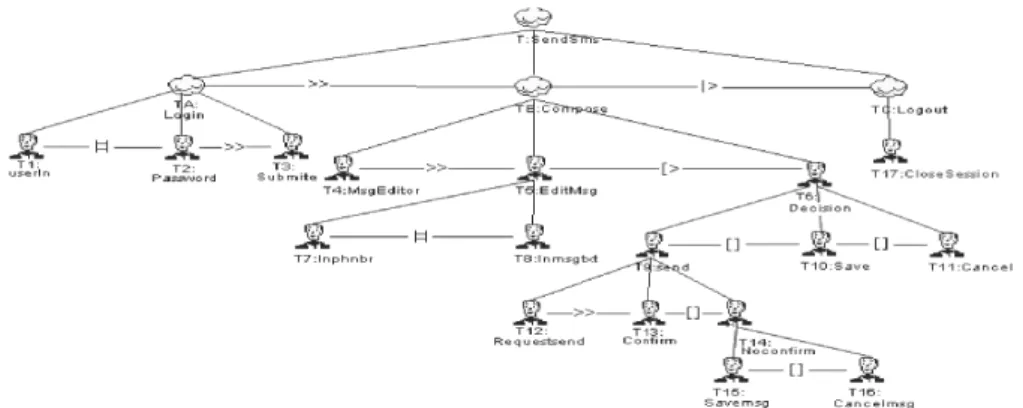
In order to illustrate the previously described formal method for checking UI plasticity, we consider the case of checking if a web application, initially designed to send SMS on a personal computer (PC), runs on a Smartphone as well. Below, we show how two task models, describing two user interfaces, concretizing the same task on these two concrete different platforms (PC and Smartphone).
A. Tasks description
Figure III-E shows the CTT task model, describing how the application UI allows a user to send an SMS. The user opens a session to access his own space (subtask T A). Then, he writes a message and sends it (subtask T B). Finally, he logs out from his own space (subtaskT C). The leaves of the defined task model are actions that a user must carry out to achieve each subtask. To login, a user gives his identifier (T1)
and password (T2) in any order and submits them (T3). Then,
he triggers the message editor (T4), edits his message (T5) by
entering the text of the message (T8) and the phone number of
the recipient (T7) (in any order). Then, he decides whether he
sends the entered message (T6) or saves it (T10) or cancels it
(T11). To send the message, the user must request the system
(T12) and confirm the action (T13). If he does not confirm
sending the message (T14), he chooses to save it (T15) or to
cancel the whole operation (T16). Finally, the user closes the
session (T17).
B. Design
In order to keep this paper in a reasonable length, we only describe the subtask EditMsg (T5). We show how our formal
approach applies to establish the similitude (equivalence) of this subtask, when deployed on a PC or on a Smartphone. The Task model of figure 5 describes how to carry out the task (T5) on the PC platform.
Fig. 5. The EditMsg subtask ( T5) deployed on a PC
The model of figure 6 shows how the same task is achieved on a Smartphone. As a consequence, two interactive systems (Systsource, Systtarget), corresponding respectively to the PC
and to the Smartphone platforms, are described.
From the task models of figures 5 and 6, a pair (ltsP c, ltsP h) of lts, formalizing the behavior of
(Systsource, Systtarget), are obtained. As mentioned
above, CTT models are formalized as LOTOS process algebra expressions and thus an lts can be associated to each CTT expression.
The lts ltsP c and ltsP h of figures 7 and 8 correspond
toSystsourceandSysttarget, respectively. They describe the
interactive system, running on a PC and on a Smartphone respectively.
Fig. 4. Send SMS abstract Task Model
Fig. 6. The EditMsg subtask ( T5) deployed on a Smartphone
1 2 3 4 5 6 7 8 9 10 11 12 13 e7 e7 e5 e7 e3e3 e7e7 e5 e1e1 e5 e7 e 1 e1e7 e7e5 e3 e3 Fig. 7. lts on PC platform
TABLE I. USER ACTIONS AND CORRESPONDING LABELS
CTT’s atomic ac-tions
Signification lts’s
Labels KeyPress CHR Press the keyboard character key e1
KeyPress NUM Press the keyboard digital key e3
Click LBTN Click the mouse left button e5
BtnPress DUDirBtn Press keypad Down/Up e6
direction button
Move Mouse Move the mouse e7
BtnPress LRDirBtn Press keypad Left/Right e8
direction button
BtnPress CentBtn Press keypad central button e10
1 2 5 3 4 6 7 8 9 10 11 13 12 14 15 16 17 e6 e8 e6 e8 e6 e8 e6 e8 e10 e10 e10 e10 e3 e1 e6 e8 e3 e6 e8 e1 e6 e8 e6 e8 e10 e10 e10 e10 e1 e1 e3 e3
Fig. 8. lts on Smartphone platform
Table I gives the correspondence between actions of task
models and the corresponding labels in the lts. C. Identification of irrelevant actions
The labels, corresponding to irrelevant actions in the task model with respect to the plasticity, are identified from the ontology. In this case study, the iterated user actions, corresponding to moving the mouse in the screen on the PC {MoveMouse}, or moving buttons on the Smartphone {BTNPressDUDirBtn, BTNPressLRDirBtn}, are considered as irrelevant. Only one iteration is considered in this case and the other iterations are set toτ for their corresponding labels (e7,
e6, e8) in ltsP c and/or ltsP h. Note that these actions could
have been kept as they are if one may consider the number of times buttons are pressed, for example.
D. Rewriting
The next step consists in rewriting the different lts, involved in the task models, corresponding to(ltsP c, ltsP h), in order to
produce new lts that share the same set of labels. LetEP cand
EP h be the set of labels, corresponding toltsP c and ltsP h,
respectively.LabDif f is the set of labels of ltsP candltsP h,
which are different.
LabDif f = (EP c ∪ EP h) − (EP c ∩ EP h)
= {e5, e6, e7, e8, e9, e10}
The set of labelsEr
s andEtrto be rewritten forltsP c, and
ltsP h, respectively, are defined below.
Er
P c = EP c∩ LabDif f EP hr = EP h∩ LabDif f
= {e5, e7} = {e6, e8, e10}
TABLE II. LABEL REWRITING TABLE
lts’s Labels Substitution action φ Application (e5, e10) GO φ(e5, e10) = g (e7, e6) MoveCursor φ(e7, e6) = m (e7, e8) MoveCursor φ(e7, e8) = m
At this level, according to the defined methodology, the rewriting function can be applied. This function is defined in table II. Figure 9 shows an excerpt of the ontology instances, used for this case study. Labels (g, m) appear after rewrit-ing. The label g, corresponding to the interactive task (INT TASK) GO, replaces the labels corresponding to User Actions (AT OM IC U A), Click that acts on LBTN, and BtnPress that acts on CentBtn; because it represents the effect of the two
actions. The label m, corresponding to the interactive task (INT TASK) MoveCursor, replaces the labels corresponding to user actions (AT OM IC U A), Move that acts on Mouse, BtnPress that acts on DUDirBtn, and BtnPress that acts on LRDirBtn.
Fig. 9. Instances of our ontology concepts used to rewrite labels
E. Checking
Once the previous steps are achieved, the labelled transition systemsltsP ctr of figure 10 and theltsP htr of figure 11 are
obtained for both the PC and the Smartphone, respectively. They share the same set of labels{e1, e3, m, g, τ }.
1 2 3 4 5 6 7 8 9 10 11 12 13 m m g τ e3e m 3 τ g e1e1 g τ e1 e1m g τ e 3 e3
Fig. 10. lts on PC platform after rewriting labels
It becomes possible to verify that the obtained lts are bi-similar by checking the observational equivalence relationship between them, i.e. by checking the weak bi-simulation rela-tionship, previously defined.
1 2 5 3 4 6 7 8 9 10 11 13 12 14 15 16 17 m m m m τ τ τ τ g g g g e3 m m m e3 m m e1 τ τ τ τ g g g g e1 e1 e3 e3
Fig. 11. lts on Smartphone platform after rewriting labels
The final result shows thatltsP ctrandltsP htr are weakly
bi-similar. Therefore, we can conclude that the task models, described on a PC and on a Smartphone, can substitute each other, ensuring thus the plasticity property.
F. Tool support
The CADP c (Construction and Analysis of Distributed
Processes) model checker [35] has been set up to model tasks and check bi-simulation. This toolbox provides resources for compiling and checking Lotos [30] programs. In our approach, the lts are first, formalized in LotosNt [35] (see figure 12),
a simplified version of LOTOS. They are transformed into LOTOS programs. Then, an internal representation, by labelled transition system (automaton) in BCG format, is generated for each LOTOS program. Finally, the bi-simulation of the two BCG automata is checked, thanks to the BISIMULATOR module, using observational equivalence relationship option.
module ltspct is
process main [m,g,e1,i,e3 :any] () is select
m; brch1[m,g,e1,e3,i] [] m; brch2[i,m,g,e1,e3] end select
end process -- main
process brch1 [m,g,e1,i,e3:any] () is select
i; brch1[m,g,e1,e3,i] [] g; e1; brch11[m,g,e1,e3,i] end select
end process -- brch1: branche1 ...
process brch23[e1:any] ()is e1; brch23[e1]
end process
end module -- ltspct
Fig. 12. A section of LOTOS NT code corresponding to ltsP ctr V. CONCLUSION
This paper presented a formal modeling approach to check the plasticity property of user interfaces. The objective is to allow UI developers check whether different user interfaces, running on different computing platforms, with different inter-action techniques, and various available interinter-action devices, support the same user tasks. The approach relies on the formalization of task models by lts, where states record the UI changes and transitions are labelled with user actions. They offer a powerful model to describe behavioral aspects of task models. Our idea, to handle plasticity of user interfaces, comes from the fact that, once task models are formalized as lts, we observe that different paths with different actions of two task models may lead to equivalent states. This notion of equivalence is hard to establish because the actions, la-beling the transitions, are not exactly the same ones. There is a need to express equivalence relations on such actions when such a relation holds. Therefore, one needs to make explicit the knowledge that some interaction devices, modes or actions have the same effect. This information represents an axiomatization of the interaction domain. We have chosen to model such a knowledge with domain ontologies, that are well adapted for the description of domain knowledge indepen-dently of any context of use. The proposed approach is based on two formal verification techniques. First, it exploits the bi-simulation relationship to compare behaviors, expressed by lts. Second, the computation of the subsumption and equivalence relationships, within an ontology provided with equivalent or subsuming instances, that can be used to safely rewrite transition labels. The interest of the proposed approach is its loose coupling between the tasks models -the user interface-and the ontology. Indeed, both may evolve independently.
Moreover, this approach can be used for handling plasticity at both design and runtime. On the one hand, checking bi-simulation overall labelled transitions systems, ensures that a global task model can substitute another one. On the other hand, the fact that the bi-simulation relationship is defined on pairs of states ensures that two bi-similar states are equivalent. Thus, it becomes possible to switch from one state of an lts to its bi-similar state, of another lts, at runtime. A case study
of a web application, sending an SMS from a Pc or from a Smartphone, showed how our approach works. It illustrates two equivalent task models modulo an interaction domain ontology.
Finally, this work opens several research perspectives. First, as for classical ontology engineering, the ontology used in this paper shall be consensual and agreed by the UI developers’ community. Second, the definition of the rewriting function should be automated. We are currently investigating how this function can be encoded within rewriting systems like Maude. Third, more complex applications should be addressed in order to show how this approach scales up to other interactive systems. Finally, we believe that the provided relational bi-simulation relationship opens research paths for studying adap-tive systems in general.
REFERENCES
[1] D. Thevenin and J. Coutaz, “Plasticity of user interfaces: Framework and research agenda,” in Proceedings of INTERACT, vol. 99, 1999, pp. 110–117.
[2] J. Coutaz and G. Calvary, “HCI and Software Engineering for User Interface Plasticity,” in HCI Handbook: Fundamentals, Evolving
Tech-nologies, and Emerging Applications, 3rd Edition, J. A. Jacko, Ed. CRC Press, 2012, pp. 1195–1220.
[3] J. A. Johnson, B. A. Nardi, C. L. Zarmer, and J. R. Miller, “Ace: building interactive graphical applications,” Communications of the
ACM, vol. 36, no. 4, pp. 40–55, 1993.
[4] S. Kawai, H. Aida, and T. Saito, “Designing interface toolkit with dynamic selectable modality,” in Proceedings of the 2nd annual ACM
conference on Assistive technologies. ACM, 1996, pp. 72–79. [5] M. Crease, S. Brewster, and P. Gray, “Caring, sharing widgets: a toolkit
of sensitive widgets,” in People and Computers Usability or Else! Springer, 2000, pp. 257–270.
[6] E. A. Bier, M. C. Stone, K. Pier, W. Buxton, and T. D. DeRose, “Toolglass and magic lenses: the see-through interface,” in Proceedings
of the 20th annual conference on CGIT. ACM, 1993, pp. 73–80. [7] W. Stuerzlinger, O. Chapuis, D. Phillips, and N. Roussel, “User interface
faades: towards fully adaptable user interfaces,” in Proceedings of
the 19th annual ACM symposium on User interface software and technology, ser. UIST ’06. New York, NY, USA: ACM, 2006, pp. 309–318.
[8] G. Calvary, J. Coutaz, L. Bouillon, M. Florins, Q. Limbourg, L. Marucci, F. Patern`o, C. Santoro, N. Souchon, D. Thevenin et al., “The cameleon reference framework,” Deliverable D1, vol. 1, 2002. [9] Q. Limbourg, J. Vanderdonckt, B. Michotte, L. Bouillon, and V.
L´opez-Jaquero, “Usixml: A language supporting multi-path development of user interfaces,” Engineering HCI and Interactive Systems, pp. 134– 135, 2005.
[10] A. Demeure, G. Calvary, and K. Coninx, “Comet(s), a software archi-tecture style and an interactors toolkit for plastic user interfaces,” in
Interactive Systems. Design, Specification, and Verification, ser. LNCS, T. Graham and P. Palanque, Eds. Springer Berlin Heidelberg, 2008, vol. 5136, pp. 225–237.
[11] B. Jabarin and T. Graham, “Architectures for widget-level plasticity,”
Interactive Systems. Design, Specification, and Verification, pp. 451– 460, 2003.
[12] A. Stanciulescu, Methodology for Developing Multimodal User
Interfaces of Information Systems (a). Presses univ. de Louvain, 2008, vol. 556.
[13] K. Samaan and F. Tarpin-Bernard, “The amf architecture in a multiple user interface generation process,” in Developing User Interfaces with
XML, AVI’2004 Workshop, 2004.
[14] A.-M. Dery-Pinna, J. Fierstone, and E. Picard, “Component model and programming: a first step to manage human computer interaction adaptation,” in Human-Computer Interaction with Mobile Devices and
Services. Springer, 2003, pp. 456–460.
[15] K. M. De Oliveira, F. Bacha, H. Mnasser, and M. Abed, “Transportation ontology definition and application for the content personalization of user interfaces,” Expert Systems with Applications, vol. 40, no. 8, pp. 3145–3159, 2013.
[16] J. Sonnenberg, “Service and user interface transfer from nomadic devices to car infotainment systems,” in Proceedings of the 2nd
In-ternational Conference on Automotive User Interfaces and Interactive Vehicular Applications. ACM, 2010, pp. 162–165.
[17] W. Dees, “Usability of nomadic user interfaces,” in Human-Computer
Interaction. Towards Mobile and Intelligent Interaction Environments, ser. LNCS, J. Jacko, Ed. Springer Berlin Heidelberg, 2011, vol. 6763, pp. 195–204.
[18] D. Masson, A. Demeure, and G. Calvary, “Examples galleries generated by interactive genetic algorithms,” in Procedings of 2nd Conf. on
Creativity and Innovation in Design. ACM, 2011, pp. 61–71. [19] D. Pierre, D. Marc, and R. Philippe, “Ubiquitous widgets: Designing
interactions architecture for adaptive mobile applications,” in
Inter-national Conference on Distributed Computing in Sensor Systems (DCOSS). IEEE, 2013, pp. 331–336.
[20] J. Vanderdonckt, D. Grolaux, P. Van Roy, Q. Limbourg, B. Macq, and B. Michel, “A design space for context-sensitive user interfaces,”
Proceedings of IASSE, 2005.
[21] A. Demeure, G. Calvary, J. Coutaz, and J. Vanderdonckt, “The comets inspector: Towards run time plasticity control based on a semantic network,” Task Models and Diagrams for UI Design, pp. 324–338, 2007. [22] K. Samaan and F. Tarpin-Bernard, “Task models and interaction models in a multiple user interfaces generation process,” in Proceedings of the
3rd annual conference on Task models and diagrams. ACM, 2004, pp. 137–144.
[23] S. Jean, G. Pierra, and Y. Ait-Ameur, “Domain Ontologies: A Database-Oriented Analysis,” in Web Information Systems and Technologies,
International Conferences, WEBIST 2005 and WEBIST 2006. Revised Selected Papers, ser. LNBIP. Springer Berlin Heidelberg, 2007, pp. 238–254.
[24] P. Dragicevic and J.-D. Fekete, “Support for input adaptability in the icon toolkit,” in Proceedings of the 6th international conference on
Multimodal interfaces. ACM, 2004, pp. 212–219.
[25] W. Buxton, “A three-state model of graphical input,” in
Human-computer interaction-INTERACT, vol. 90. Citeseer, 1990, pp. 449– 456.
[26] S. Berti, F. Patern`o, and C. Santoro, “A taxonomy for migratory user interfaces,” in Interactive Systems. Design, Specification, and
Verification. Springer, 2006, pp. 149–160.
[27] D. Navarre, P. Palanque, and S. Basnyat, “A formal approach for user interaction reconfiguration of safety critical interactive systems,” in
Computer Safety, Reliability, and Security. Springer, 2008, pp. 373– 386.
[28] L. L. Constantine, “Canonical abstract prototypes for abstract visual and interaction design,” in Interactive Systems. Design, Specification,
and Verification. Springer, 2003, pp. 1–15.
[29] F. Patern`o, C. Mancini, and S. Meniconi, “Concurtasktrees: A diagram-matic notation for specifying task models,” in Proceedings of the IFIP
TC13 Interantional Conference on HCI, vol. 96, 1997, pp. 362–369. [30] I. Lotos, “A formal description technique based on the temporal ordering
of observational behaviour,” ISO/IEC JTC 1/SC 7, Geneva, 1988. [31] R. Milner, A Calculus of Communicating Systems. Secaucus, NJ, USA:
Springer-Verlag New York, Inc., 1982.
[32] ——, Communication and concurrency. Upper Saddle River, NJ, USA: Prentice-Hall, Inc., 1989.
[33] S. Card, J. D. Mackinlay, and G. Robertson, “The design space of input devices,” in Proceedings of ACM Conference on Human Factors
in Computing Systems, Multi-Media, ser. CHI90, 1990, pp. 117–124. [34] D. Frohlich, “The design space of interfaces,” in Multimedia Systems,
Interaction and Applications, 1st Eurographics Workshop. Springer Verlag, 1991.