HAL Id: lirmm-02309368
https://hal-lirmm.ccsd.cnrs.fr/lirmm-02309368
Submitted on 9 Oct 2019
HAL is a multi-disciplinary open access
archive for the deposit and dissemination of
sci-entific research documents, whether they are
pub-lished or not. The documents may come from
teaching and research institutions in France or
abroad, or from public or private research centers.
L’archive ouverte pluridisciplinaire HAL, est
destinée au dépôt et à la diffusion de documents
scientifiques de niveau recherche, publiés ou non,
émanant des établissements d’enseignement et de
recherche français ou étrangers, des laboratoires
publics ou privés.
A Bounding Volume of the Cable Span for Fast Collision
Avoidance Verification
Maximilian Lesellier, Marc Gouttefarde
To cite this version:
Maximilian Lesellier, Marc Gouttefarde. A Bounding Volume of the Cable Span for Fast Collision
Avoidance Verification. CableCon: Cable-Driven Parallel Robots, Jun 2019, Krakow, Poland.
pp.173-183, �10.1007/978-3-030-20751-9_15�. �lirmm-02309368�
Collision Avoidance Verification
M. Lesellier, M. Gouttefarde
LIRMM, Universit´e de Montpellier, CNRS, Montpellier France ICUBE, Universit´e de Strasbourg
Abstract. The problem of verifying the absence of collision between a cable and the mobile part(s) of a device located on-board the mobile platform of a Cable-Driven Parallel Robot (CDPR) is addressed. The set of all positions taken by one cable of the CDPR for all the poses of the mobile platform in a prescribed workspace is called the cable span. A simple bounding volume approximation of the cable span is proposed in this paper. This bounding volume is a polyhedron and the characterization of the faces of this polyhedron is discussed. Using this polyhedron as a bounding volume of the cable span allows to accelerate computations related to collision avoidance checking.
Keywords: Cable-Driven Parallel Robot, Cable, Span, Collision
1
Introduction
Cable-Driven Parallel Robots (CDPRs) consist of a mobile platform driven by cables. Using cables instead of rigid links gives CDPRs interesting characteristics such as a potentially very large workspace, large payload-to-weight ratio, and high dynamics capabilities.
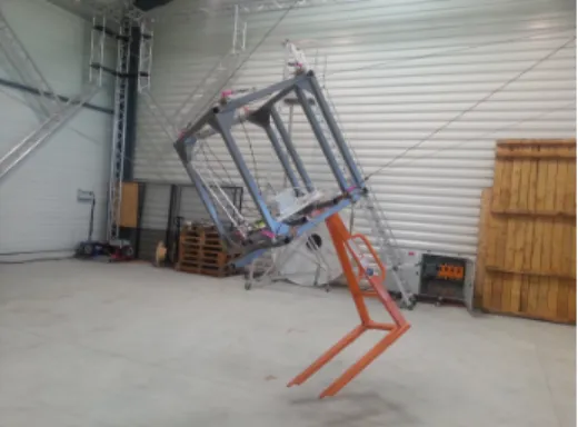
However, one of the major drawbacks of CDPRs is their low stiffness due to the use of cables. This low stiffness may be the cause of vibrations affecting the platform positioning accuracy. Several techniques can be used to damp these vibrations: input shaping [1], modal space control [2], or active damping by creating a transient wrench to compensate the vibrations. This wrench can be created by additional actuated stabilizing mechanical devices placed on board the mobile platform [3–6]. In reference [5], a stabilizer consisting of rotating arms is located on-board the CDPR mobile platform to actively damp vibrations, as illustrated in Figure 1. The work reported in the present paper is part of a project aiming to embed a similar stabilizer on the platform of the 6 Degree-of-Freedom (DOF) CDPR CoGiRo [7], shown in Figure 2.
The design of CoGiRo ensures that there is no cable collision nor cable-platform collision within the workspace of this CDPR. However, when active mechanical devices are placed on-board the CDPR mobile platform, the moving parts of these on-board devices may collide with the cables or platform. This eventuality of collisions is an issue that must be taken into account in the design
• • • • • • • A1 A2 A3 B1 B2 B3 Gp k1, l01 k2, l02 k3, l03 − →z 0 − →y 0 − →z p − →y p rrr1 O1 λ λ λ1 m1 θ1 rrr2 O2 λλλ2 m2 θ2 rrr3 O3 λ λ λ3 m3 2π − θ3 − →z 0 Gp −→y0 − →z p −→yp α
Fig. 1: Planar 3-DOF CDPR with 3 stabilization arms
Fig. 2: 6-DOF CDPR CoGiRo
optimization of on-board active devices. In order to prevent such collisions, a first step is to determine the volume of space occupied by each cable when the CDPR platform moves throughout a given workspace. Indeed, during the platform motions, the positions of the cables change. The set of all positions taken by one cable for all the poses of the platform in the CDPR workspace is called cable span [8]. The latter reference is the only previous work dealing with the issue of determining the cable span. It proposes a method to represent the cable span by a volume object but it does not deal with the issue of using this volume to check the absence of collisions.
While the problem of cable-cable interferences as well as cable-platform and cable-object collisions has been addressed several times in the literature, e.g. [9–13], to the best of our knowledge, the problem of avoiding collisions between a cable and the mobile part(s) of a device located on-board the CDPR platform
has never been treated yet. Hence, the contribution of this paper is a method to check the absence of such collisions within a box-shaped workspace of a CDPR. In order to accelerate computations related to collision avoidance checking, this method is based on an original bounding volume approximation of the cable span which is simpler than the one discussed in [8]. Moreover, this cable span approximation is calculated with respect to the mobile platform frame to enable simple testing of collisions with on-board devices.
This paper is organized as follows. The cable span of a CDPR is defined in Section 2. Based on the approximation of the cable span introduced in [8], two algorithms are discussed in Section 3 to test the eventuality of a collision between a cable and an object located on-board the mobile platform. A new and simpler bounding volume approximation of the cable span is proposed in Section 4. The characterization of the faces of this bounding volume and the corresponding collision avoidance testing are finally presented in Section 5.
2
Definition of the cable span
The frame attached to the CDPR mobile platform is denoted Fp and the fixed
base frame is denoted F0. A vector vvv expressed in frame F0 is denoted by 0vvv
and in Fp by pvvv. The pose of the platform is given by the vector xxx, composed
of its position vector ppp in F0 and of a vector θθθp of three Euler angles defining
the orientation of Fp in F0. Let RRR(θθθp) be the rotation matrix describing the
orientation of the platform in F0. Each cable is considered to be a straight line
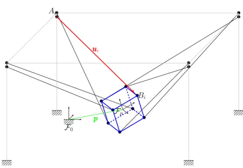
segment between its base drawing point Ai and its platform fixing point Bi.
These notations are shown in Figure 3.
The vector along the straight line segment of cable i, denoted uuui, is given in
frame F0 by:
0uuu
i= 0ppp + RRR(θθθp)pbbbi− 0aaai (1)
The interval that contains all values of a scalar variable e is denoted [e, e], with e the minimal value of e (lower bound) and e its maximal value (upper bound). The concatenation operator is written ||. In this paper, the prescribed workspace W of a 6-DOF CDPR is defined as follows:
W = { xxx = {0ppp, θθθp} | {0ppp ∈ [x, x] × [y, y] × [z, z]}
|| {θθθp∈ [αp, αp] × [βp, βp] × [γp, γp] } }
(2)
It is a box-shaped workspace in the sense that, for a given orientation θθθp, the
set of positions lying inside W is a box. In the remainder of this paper, it is assumed that W is fully included in the wrench-feasible workspace [14, 15] and, hence, that all poses in W can be reached with feasible cable tensions.
The cable span of cable i with respect to F0 is defined as CS0i = {0uuui | xxx ∈
W}. Vector 0uuu
i is defined in (1) and according to the right-hand side of this
equation and to (2), CS0i is the Minkowski sum of three sets: – The box [x, x] × [y, y] × [z, z] (position vectors 0ppp)
• • • • • • • • F0 • • • • • • • • Fp Bi Ai u uui p p p
Fig. 3: Schematic of the CoGiRo CDPR
– The portion of a sphere {RRR(θθθp)pbbbi | θθθp∈ [αp, αp] × [βp, βp] × [γp, γp]}
– The point Ai having as position vector 0aaai
Note that pbbbi and 0aaai are constant vectors. Hence, when the Euler angle set
[αp, αp] × [βp, βp] × [γp, γp] is not reduced to a single value, the cable span is a
relatively complex geometric object (not necessarily convex) even for the simple definition of the workspace W given in (2). In [8], based on a discretization of the CDPR workspace and for a fixed orientation of the mobile platform, the cable span is approximated as a so-called generalized cone (a kind of cone whose cross section is a polygon not necessarily convex).
With the aim of checking the absence of collisions between a cable and the mobile part(s) of a device located on-board the mobile platform of a CDPR, the present paper deals with the cable span calculated with respect to the mobile platform frame Fp. For cable i, this cable span is defined as CS
p i = {− puuu i | xxx ∈ W} where: −puuu i= RRR(θθθp)>(0aaaiii−0ppp) − pbbbi (3)
Equation (3) is directly obtained from (1) by multiplying both sides by RRR(θθθp)>.
CSip is thus the translation of the set {RRR(θθθp)>( 0aaaiii−0ppp) | xxx ∈ W} by vector pbbb
i. This set corresponds to the volume swept by the box { 0aaaiii−0ppp | 0ppp ∈
[x, x] × [y, y] × [z, z]} when this box is rotated by RRR(θθθp) for all θθθp in [αp, αp] ×
[βp, βp]×[γp, γp]. Similarly to the case of the cable span CS0i calculated in F0, the
cable span CSpi is thus a relatively complex three-dimensional geometric object which is not necessarily convex.
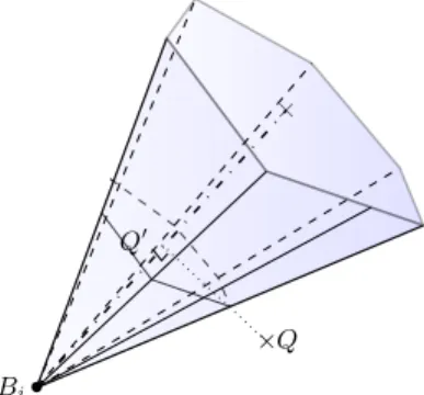
× • × Bi Q Q0
Fig. 4: Convex polyhedral cone containing the cable span
3
Collision avoidance checking
In [8], based on a discretization of the CDPR workspace W, the cable span CS0i is approximated as a so-called generalized cone. The same method could
be applied to the cable span CSpi. This generalized cone approximation is not necessarily convex (see Figure 3 in [8]) and may contain a large number of vertices depending on the number of points in the workspace discretization (and on the workspace definition). Therefore, it is not well suited for checking the absence of collision between a cable and mechanical parts on-board the mobile platform since this check consists in verifying that the volumes swept by the mechanical parts during their motions are fully outside of the cable span.
As an example, let us consider the convex polyhedral cone shown in Figure 4. Note that this cone is a simpler geometric object than the generalized cone considered in [8]. Let us also consider the simple case of testing whether or not a point Q is located inside this convex polyhedral cone. Several algorithms can be used to determine if Q is inside the cone, two of them are now briefly described. First, a point-in-polygon approach, whose principle is illustrated in Figure 4, performs the following steps:
1. Obtain Q0the projection of Q on the axis of the cone. This defines a ratio k of, on the one hand, the distance between the base of the cone and Q0 and, on the other hand, the length of the cone axis.
2. Apply the ratio k to the distances between the vertices of the base of the cone, which is a polygon, and the center of this polygon. The new polygon hereby obtained called P0 is the section of the cone containing the point Q0. 3. Test whether or not Q belongs to the polygon P0.
The third step can be implemented with a ray crossing algorithm [16] (which can also be used for non-convex polygons) whose complexity is O(n), n being the number of vertices of the base polygon.
Another approach consists first in determining the faces of the convex poly-hedral cone. These faces may be given by the convex hull procedure or they can
be determined within the polar sorting phase of the generalized cone determina-tion as detailed in [8]. Then, point Q is located inside the polyhedral cone if and only if it is located on the same side of each of the planes containing the cone faces. This second approach complexity is also O(n) where n is the number of vertices (or edges) of the base polygon.
The number of vertices n depends on the number of points used to discretize the CDPR prescribed workspace. Hence, the computational time needed to test if a given set is not interfering with the cable span, i.e. to check the absence of collision, depends on n. Moreover, the check must be done N times, N being the number of cables. Hence, using one of the two algorithms described above within an iterative optimization process slows down the whole procedure when n is (relatively) large. Using a simple, yet not overly conservative, bounding volume approximation of the cable span is thus important to enhance computational efficiency.
4
A simple bounding volume approximation of the cable
span
Based on a discretization of the CDPR workspace W, a simple bounding volume of the cable span CSpi (cable span in Fp) can be obtained as follows.
Cable i is considered as a straight line segment between points Ai and Bi.
In the mobile platform frame Fp, the position of Bi is constant whereas the
position vector of point Aiis RRR(θθθp)>(0aaaiii−0ppp) and thus it depends on the mobile
platform pose xxx = {0ppp, θθθ
p} ∈ W. In Fp, the discretization of W generates a set
of positions of point Aiand taking the convex hull of all these points produces a
convex polyhedron. If the discretization is fine enough, this convex polyhedron is a good approximation of all possible positions of Aiin Fpwhen xxx ∈ W. However,
as discussed in Section 3, the number of vertices of the bounding volume of the cable span should be kept small. Hence, instead of the convex hull, the smallest box B (aligned with the axes of Fp) containing all positions of point Aifor xxx in
the discretized workspace W is calculated. To this end, it suffices to determine, along each of the three coordinate axes of Fp, the minimum and maximum
coordinates of this set of positions of Ai.
The box B encloses all positions of points Ai in Fp for xxx in the discretized
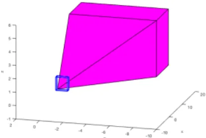
workspace W, as illustrated in Figure 5. Hence, the polyhedron P obtained by connecting the fixed point Bi to B is a bounding volume approximation of the
cable span CSpi, i.e., a bounding volume of all the positions of the cable segment AiBi for xxx in the discretized workspace W. In the remainder of this paper, it is
assumed that the discretization of the workspace is such that this polyhedron P encloses the cable span CSpi.
An example of such a polyhedron P forming a bounding volume approxima-tion of the cable span is shown in Figure 6. As can be seen in this figure, P consists of the union of the box B and of a pyramid (convex polyhedral cone) having the fixed point Bias apex. The base of this pyramid is a convex polygon
Fig. 5: Convex hull of all possible po-sitions of Ai (and of the fixed point
Bi) and box containing the convex
hull
Fig. 6: Bounding volume approxima-tion of the cable span: The union of a box and a pyramid
5
Collision avoidance checking with the new cable span
bounding volume approximation
In Section 4, a polyhedron P forming a bounding volume approximation of the cable span CSpi has been introduced. A method to ensure collision avoidance between a cable and a moving device on-board the CDPR mobile platform con-sists in testing if the set of all possible positions of this device does not intersect P. Indeed, P being a bounding volume of the cable span CSpi, no intersection with P means no intersection with the cable span and thus no possible colli-sion with the cable in the workspace W. In order to test if a point or a set is outside polyhedron P, the determination of the polyhedron faces is useful. In-deed, the polyhedron can be defined as the intersection of halfspaces bounded by the planes containing the faces (mathematically, a system of linear inequalities). Then, a point or a set is outside the polyhedron if and only if it is outside of at least one of these halfspaces (it violates at least one of the inequalities). The method to determine the faces of the polyhedron P forming a bounding volume approximation of the cable span is described below.
As mentioned at the end of Section 4, the polyhedron P is the the union of the box B and of a pyramid, the apex of the pyramid being the fixed point Bi
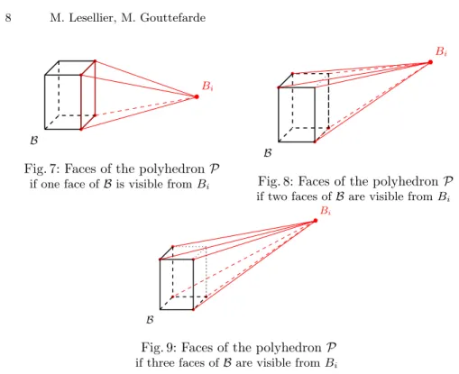
(Fig. 6). The number of faces of this polyhedron depends on the number of faces of the box B that are visible from point Bi. Three cases must be distinguished.
– One face of B is visible from Bi: As shown in Figure 7, P consists of nine
faces. Four of these faces are triangles which form the pyramid. Point Bi,
the apex of the pyramid, is a vertex common to these four faces. The five other faces of P are the faces of the box B that are not visible from Bi.
– Two faces of B are visible from Bi: As shown in Figure 8, P consists of ten
faces. Six of these faces form the pyramid with point Bias a common vertex.
• • • • •Bi B
Fig. 7: Faces of the polyhedron P if one face of B is visible from Bi
• • • • •Bi B
Fig. 8: Faces of the polyhedron P if two faces of B are visible from Bi
• • • • • • •Bi B
Fig. 9: Faces of the polyhedron P if three faces of B are visible from Bi
– Three faces of B are visible from Bi: As shown in Figure 9, P consists of nine
faces. Six of these faces form the pyramid with point Bias common vertex.
The three other faces of P are the faces of B that are not visible from Bi.
In addition to these three cases, particular cases must be dealt with. These particular cases appear when point Bi lies in one or several planes containing
the faces of the box B. For simplicity, these particular cases are not detailed in this paper. They do not cause any particular difficulty.
Based on this characterization of the faces of the polyhedron P, the mathe-matical description of each of these faces is straightforward. Let us consider face k of P. Its mathematical description consists in a point Pklying on the face and
a vector nnnk normal to the face and pointing to the outside of P. Point Pk and
vector nnnk define the plane containing face k. A point Q is then outside of the
polyhedron if and only if, for at least one face k, it is not on the same side of this plane than P, i.e., if and only if there exists k such that−−→PkQ · nnnk> 0.
In the case of a face k of P which is also a face of the box B (a rectangle), point Pk can for instance be one vertex of the rectangle or its center and vector
nnnkis taken along the normal to this rectangle pointing to the outside of B. In the
case of a face of the pyramid having point Bias apex, the face is a triangle whose
three vertices are known so that point Pk and vector nnnk are also straightforward
to define. Note that the determination of the faces of P and the calculation of their mathematical descriptions (Pk and nnnk) can be done offline, i.e., before
any use of P to test the absence of collision between a cable and a device on-board the CDPR mobile platform. Typically, within an iterative optimization
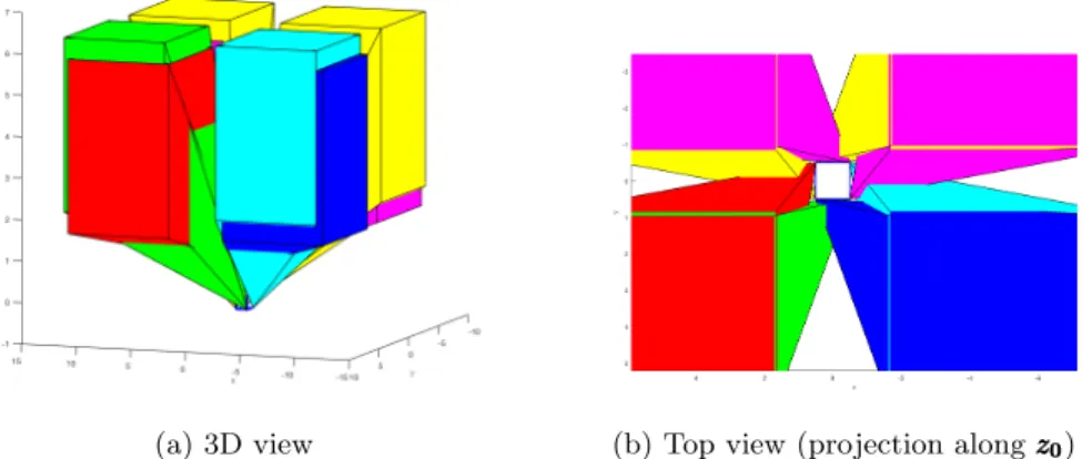
(a) 3D view (b) Top view (projection along zzz000)
Fig. 10: All the bounding volumes of the cable spans of the CDPR CoGiRo as seen in the platform frame Fp
process, only dot products (−−→PkQ · nnnk) need to be calculated. Consequently, the
computation cost of testing collision avoidance with the cables across the CDPR workspace is small.
Figure 10 show the polyhedra P which are bounding volume of the cable spans of the eight cables of the CDPR CoGiRo for a given workspace W. As can be seen, the cable span bounding volumes represent a significant part of the space around the platform and, in fact, surround the platform. This is mostly due to the cable arrangement of CoGiRo [7]. This CDPR being suspended, it can also be observed that the space below the platform is free.
6
Conclusion
This paper dealt with the problem of verifying the absence of collisions between the cables of a CDPR and mobile devices located on-board the mobile platform, across a prescribed workspace. The cable span is defined as the set of all positions taken by one cable of the CDPR for all the poses of the mobile platform in the prescribed workspace. In this paper, the cable span as seen in the platform coordinate frame is considered. If the set of all possible motions of a device on-board the mobile platform is fully outside of the cable span, then no collision between the device and the cable can occur within the prescribed workspace. However, the cable span being a relatively complex geometric object, a bounding volume approximation of the cable span has been proposed in this paper. This bounding volume is a polyhedron and the characterization of the faces of this polyhedron has been given. Using this polyhedron as a bounding volume of the cable span allows to accelerate computations related to collision avoidance checking.
7
Acknowledgement
This work was supported by the ANR under grant ANR-15-CE10-0006, project DexterWide.
References
1. Forrest Montgomery and Joshua Vaughan. Suppression of cable suspended parallel manipulator vibration utilizing input shaping. In Conference on Control Technol-ogy and Applications, 2017.
2. Xavier Weber, Lo¨ıc Cuvillon, and Jacques Gangloff. Active vibration canceling of a cable-driven parallel robot in modal space. In IEEE International Conference on Robotics and Automation, 2015.
3. Rushton, Mitchell. Vibration control in cable robots using a multi-axis reaction system. Master’s thesis, Univ. Waterloo, 2016.
4. Xavier Weber, Loc Cuvillon, and Jacques Gangloff. Active vibration canceling of a cable-driven parallel robot using reaction wheels. In IEEE/RSJ International Conference on Intelligent Robots and Systems, 2014.
5. Maximilian Lesellier, Lo¨ıc Cuvillon, Jacques Gangloff, and Marc Gouttefarde. An active stabilizer for cable-driven parallel robot vibration damping. In IEEE/RSJ International Conference on Intelligent Robots and Systems, 2018.
6. R. de Rijk, M. Rushton, and A. Khajepour. Out-of-plane vibration control of a planar cable-driven parallel robot. IEEE/ASME Transactions on Mechatronics, 23(4):1684–1692, 2018.
7. Marc Gouttefarde, Jean-Fran¸cois Collard, Nicolas Riehl, and C´edric Baradat. Ge-ometry selection of a redundantly actuated cable-suspended parallel robot. IEEE Transactions on Robotics, 31(2), 2015.
8. Andreas Pott. Determination of the cable span and cable deflection of cable-driven parallel robots. In C. Gosselin, P. Cardou, T. Bruckmann, and A. Pott, editors, Cable-Driven Parallel Robots. Springer, 2017.
9. Jean-Pierre Merlet. Analysis of the influence of wires interference on the workspace of wire robots. In Advances in Robot Kinematics (ARK), 2004.
10. Martin J-D Otis, Simon Perreault, Thien-Ly Nguyen-Dang, Patrice Lambert, Marc Gouttefarde, Denis Laurendeau, and Cl´ement Gosselin. Determination and man-agement of cable interferences between two 6-dof foot platforms in a cable-driven locomotion interface. IEEE Transactions on Systems, Man, and Cybernetics-Part A: Systems and Humans, 39(3), 2009.
11. Simon Perreault, Philippe Cardou, Cl´ement M Gosselin, and Martin J-D Otis. Geometric determination of the interference-free constant-orientation workspace of parallel cable-driven mechanisms. Journal of Mechanisms and Robotics, 2(3), 2010.
12. D. Q. Nguyen and M. Gouttefarde. On the improvement of cable collision detection algorithms. In T. Bruckmann and A. Pott, editors, Cable-Driven Parallel Robots, pages 29–40. Springer, 2014.
13. A. Martin, S. Caro, and P. Cardon. Geometric determination of the cable-cylinder interference regions in the workspace of a cable-driven parallel robot. In C. Gos-selin, P. Cardou, T. Bruckmann, and A. Pott, editors, Cable-Driven Parallel Robots, pages 117–127. Springer, 2017.
14. Paul Bosscher, Andrew T Riechel, and Imme Ebert-Uphoff. Wrench-feasible workspace generation for cable-driven robots. IEEE Transactions on Robotics, 22(5):890–902, 2006.
15. Marc Gouttefarde, David Daney, and Jean-Pierre Merlet. Interval-analysis-based determination of the wrench-feasible workspace of parallel cable-driven robots. IEEE Transactions on Robotics, 27(1), 2011.
16. J. O’Rourke. Computational Geometry in C. Cambridge University Press, 2nd edition edition, 1998.