Plasma Science and Fusion Center
Massachusetts Institute of Technology
Cambridge MA 02139 USA
This work was supported by the U.S. Department of Energy, Grant
DE-FC02-99ER54512. Reproduction, translation, publication, use and disposal, in whole or in part,
by or for the United States government is permitted.
Submitted for publication to Nuclear Fusion.
PSFC/JA-06-44
Alcator C-Mod Ion Cyclotron Antenna Performance
S.J. Wukitch, T. Graves, Y. Lin, B. Lipschultz, A. Parisot,
M. Reinke, P.T. Bonoli, M. Porkolab, I.H. Hutchinson, E. Marmar,
and the Alcator C-Mod Team
Alcator C-Mod Ion Cyclotron Antenna Performance
S.J. Wukitch, T. Graves, Y. Lin, B. Lipschultz, A. Parisot, M. Reinke, P.T. Bonoli, M. Porkolab, I.H. Hutchinson, E. Marmar, and the Alcator C-Mod Team
MITPlasma Science and Fusion Center, Cambridge MA 02139 USA Email: [email protected]
Abstract. One of the keys to successful ion cyclotron range of frequency (ICRF) heating is antenna performance. In Alcator C-Mod, we have investigated the compatibility of high power ICRF antennas with high performance plasmas and all high-Z plasma facing components, to provide operational information for future devices such as ITER. Boronization appears to be critical to control plasma radiation but it can be quickly eroded particularly in the presence of ICRF. Here we present circumstantial evidence that suggests RF-enhanced sheaths on flux tubes passing near the antennas terminating on the top of the outer divertor are the most likely erosion mechanism. In addition, antenna operation without a Faraday screen was found to degrade antenna performance through increased impurity production local to the antenna. Analysis suggests that this impurity source might be reduced or mitigated by modifying the antenna strap design. At high neutral pressure, the antenna voltage handling degraded rapidly above a threshold, so-called neutral pressure limit. This degradation was confirmed by benchtop experiments to be related to discharge formation in the vacuum coaxial lines of the antenna feedlines. Reducing the secondary emission coefficient below unity for these regions was shown in tests to substantially raise this limit.
1.0 Introduction
Ion cyclotron range of frequency (ICRF) heating is expected to be an important auxiliary heating source for ITER and future fusion reactors. Critical to ICRF utilization is antenna performance and a number of issues can limit the antenna performance including poor voltage and power handling, impurity production, strong RF plasma edge interactions, poor RF coupling, and localized heating of the antenna structure. In this paper, antenna performance will refer to the increase in stored energy per input power which is of course affected by confinement and impurities as well as RF heating efficiency.
Alcator C-Mod has developed a set of experimental tools and capabilities that enable unique ICRF compatibility studies. C-Mod’s molybdenum plasma facing components (PFCs) allow operational experience with high Z PFCs useful for predicting ITER and reactor situations where tungsten is planned. Utilizing electron cyclotron (EC) resonance discharges for application of the boronization coating allows the boron deposition to be applied over small ranges of major radius. Since the PFC surfaces are molybdenum, the boron coatings can also be removed more readily than for carbon PFCs. The localized nature of the boronization affords an opportunity to identify whether the boron coating must cover all PFCs, localize where the boron coating is most effective, and characterize its lifetime. Further, we have a flexible ICRF system that enables comparisons between antennas. In this paper, we will report results from high power operation with metallic PFC’s, Faraday screen-less operation, and an investigation into a mechanism limiting the antenna voltage at high neutral pressure.
2.0 Experimental Description
Alcator C-Mod is a compact (major radius R = 0.67 m, minor radius a = 0.22 m), high field (BT ≤ 8.1 T) diverted tokamak[1]. The discharges analyzed here are lower single null D(H) or D(3He) minority (minority in parentheses) ICRF heated discharges. The on-axis toroidal fields, BT, were 5.1-5.4 T, and the plasma current, Ip, was 1 MA. The ICRF heating power is
coupled to the plasma via three fast wave antennas. The two-strap antennas, D and E,[2] are operated in dipole (0,π) phasing, at 80.5 and 80 MHz, respectively and the four-strap
antenna, J,[3] is operated at 78 MHz and 50 MHz in dipole phase (0,π,0,π) and heating phase (0,π,π,0), respectively. Prior to the 2005 run campaign, all the C-Mod antenna tiles were changed from BN to Mo protection tiles with particular care taken to ensure proper tile alignment. Furthermore, the 4-strap antenna was operated without the septum that had been added in a previous run campaign with BN protection tiles.
The primary plasma diagnostics for these experiments are the stored plasma energy (WMHD) derived from EFIT [4] and impurity diagnostics. Specifically, bolometers monitor total plasma radiation [5,6,7] and vacuum ultraviolet spectroscopy measures [8] specific impurity species. Of particular interest for these experiments are Mo (Mo XXXI 116A) [9] and Cu (Cu XVIII 234.2 A). The Mo and Cu densities are inferred using the measured line brightnesses, Thomson scattering electron density and temperature profiles, the MIST impurity transport code [10], transport coefficients [11] and cooling curves [12,13,14]. A grating polychromator (GPC)[15] and 2nd harmonic heterodyne (FRCECE) electron cyclotron emission diagnostics[16] measure electron temperature and Thomson scattering measures plasma density[17,18]. The diagnostic positions are mapped to the plasma mid-plane or flux surface position via EFIT. The H to D ratio is measured by the ratio of Hα to Dα in the plasma edge.[19]
For the plasmas with the best performance (highest HITER-89 value), the plasma radiation is controlled by coating all PFCs with a thin layer of B to control high Z impurities. C-Mod utilizes a boronization process that uses a helium diborane mixture (20% B2D6, 80% He or 10% B2D6, 90% He) as the working gas, 2-3 kW of 2.45 GHz source, and a purely toroidal field, typically ~0.1 T, to place the electron cyclotron in the chamber to create a plasma discharge. To enhance toroidal uniformity, the diborane is injected into the chamber through a single tube that splits into two, half turn, toroidal tubes with holes spaced ~1 cm. A thin boronization layer can also be applied between full tokamak discharges and is typically eroded by one RF heated discharge. For the experiments described herein, the between-discharge-boronization (BDB) is performed by sweeping the ECDC resonance location between 0.65 m and .75 m for 10 minutes resulting in a boron layer estimated to be 15-20 nm.[20]
3.0 Antenna Operation with all Metal Plasma Facing Components
High power density antenna operation, with all metal protection tiles and PFCs, present significant challenges to ICRF antenna operation, particularly for impurity generation. In C-Mod where the PFCs are molybdenum, the fractional Mo concentration at which the Mo radiation negatively impacts plasma performance is ~10-4. For low Z materials like boron, the concentration limit is set by plasma dilution instead of bulk radiation and boron is typically of order 1% in post boronized C-Mod discharges. Furthermore, Mo has a cooling rate that is peaked just below 1 keV, making it a strong edge radiator near the pedestal region for typical C-Mod discharges. In ITER, the peak cooling rate for tungsten is 2-4 keV, and expected to be a strong radiator in the edge pedestal region. Strong edge radiators could clamp the pedestal temperature resulting in reduced H-mode performance.
Impurity production associated with ICRF is generally accepted to be a result of enhanced sputtering caused by substantially higher sheath voltages (~500 V) than thermal sheaths
(~3Te).[21] These enhanced sheaths are both local to antenna elements and to locations such as plasma limiters and divertor tiles.[22] A simple description of RF sheaths is as follows: an open field line with its ends terminating on conducting surfaces encloses an area where RF flux leads to voltage fluctuation at the RF frequency on this field line. Since the electrons are much more mobile, electrons are preferentially lost to conducting surfaces, but the sheath potential rises to inhibit electron losses to maintain ambipolarity. This enhanced sheath potential is essentially DC, leading to the term sheath-rectification. The increased plasma potential translates to higher ion energy impinging upon PFCs and higher sputtering yield due to non-thermal ions. The importance of an impurity source to the core impurity content is dependent upon not only the
source strength but the impurity penetration as well.
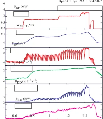
A comparison of molybdenum PFC operation both with and without boron coatings has been reported earlier[23]. In ICRF-heated discharges utilizing molybdenum PFCs without boron-coatings, H-modes were readily achieved, but had relatively modest enhancement in energy confinement, typically HITER-89 ≤ 1.2. In these H-modes, the molybdenum concentration increased rapidly after the H-mode transition, resulting in high plasma radiation, reduced energy confinement and poor plasma performance. Upon boronization, the molybdenum concentrations were strongly reduced and record C-Mod stored energy and world record volume averaged plasma pressures, ~1.8 atm, were achieved concurrent with a large drop in Mo radiation. In the discharge shown in Figure 1, the maximum RF power is 5.25 MW and the discharge is terminated by a large sawtooth crash. The antenna power density is ~9 MW/m2 for this discharge about 50% higher than that anticipated for ITER without significant impurity events local to the antenna. Previously, antenna operation at high power density with RF metallic limiters was limited by strong interactions, particularly the J antenna protection tiles.[24] The most important modification appears to have been the proper alignment of these RF limiters to eliminate peaked power deposition.
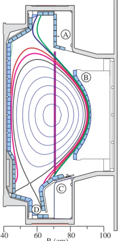
Control of the impurity influx using boronization is temporary. In C-Mod, we find that after ~ 20 ICRF-heated discharges, corresponding to ~50 MJ injected ICRF energy, the Mo levels have risen and the confinement degraded[9]. Furthermore for Ohmic H-mode discharges with similar input energy (discharge integrated), the plasma performance degradation occurs at a rate 3-4 times slower than RF heated discharges[25] clearly indicating that the ICRF is enhancing the erosion of the boronization layer and generating the subsequent Mo. From post-campaign inspections, the boron layer is removed from only a few regions: the outer divertor strike point (point ‘D’ in Figure 2); the upper gusset tiles (Figure 2, ‘A’), tiles on the top of the outer divertor (Figure 2, ‘C’), and plasma limiters (Figure 2, ‘B’). Additional experiments showed that the dominant impurity source was outside the divertor, either the
2 4 PRF (MW) 0.1 0.2 0.3 WMHD (MJ) 2 3 4 BT=5.4 T, IP=1 MA 1050426022 2 4 1 2 RDD (x1014 s-1) 0.6 0.8 1 1.2 1.4 1 2 3 PRad (MW) 6 Te0 (keV) ne (x1020 m-3) Time (s)
Figure 1: Record plasma pressure discharge with
upper gusset tiles and/or the top of the outer divertor[25]. Although previous experiments showed that the Mo generated at the RF limiters tracked the central Mo content indicating a correlation,[26] the plasma performance and core Mo content were unimproved when the Mo RF limiter tiles were replaced with insulating BN tiles.[27] This suggests the antenna structure, RF limiter, and plasma limiter Mo sources are secondary compared with some other source.
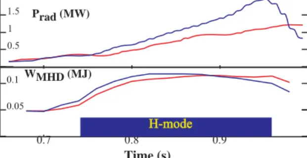
To identify the RF related Mo source, we have mapped magnetic flux tubes from various parts of the antennas to PFC surfaces around the vessel. The open flux tubes that pass in front of the antenna and terminate on the top of the outer divertor were of most interest. These flux tubes would have been unaffected by installing insulating limiters and are in the approximate region where the BDB was most effective at controlling radiated power. Shown in Figure 2 and Figure 3 are the poloidal and toroidal projections of field lines passing in front of both D+E and J antennas. Flux tubes from both antennas terminate on top of the outer divertor with their other end resting on the upper gusset tiles, inner wall, or inner divertor and each antenna maps to different toroidal location. If sheath rectification is responsible for the boronization erosion and subsequent impurity production, one should be able to run successive discharges using different antennas and achieve similar performance. To test this hypothesis, a series of discharges were run where the first discharge following a BDB was heated by one antenna or another (in this case D+E are utilized as one antenna) followed by a second discharge using a different antenna (without additional BDB). An example of such a discharge sequence is shown in Figure 4 where the discharge is first heated by the D+E antenna combination (red) followed by a discharge heated by the J antenna alone (green). The performance of the discharge heated with J alone has similar performance and radiation as the first discharge. Also shown is a representative second discharge using D+E that has the typical increased radiation and reduced performance. Interestingly, further experiments showed that the degradation in performance (which we link to erosion of the boronization) was slower for the J antenna compared to D+E antennas where the stored energy degradation and radiated power
C G D 40 60 80 100 R (cm) A B C D
Figure 2: Poloidal cross section of
C-Mod discharge showing (a) upper gussets, (b) plasma limiter, (c) outer divertor, poloidal projection of field lines passing in front of antenna and terminating on outer divertor, and (d) location of electron cyclotron resonance where impurities are best controlled for BDB.
J Ant
D+E
K
A
B
C
H
G
F
LH RF Limiter Plasma LimiterFigure 3: Toroidal projection of field
lines passing near the antenna and terminating on outer divertor for the D+E (red lines and shaded region) and J antenna (blue lines and shaded region showing the toroidal localization.
increase is slower for the J antenna than for D+E antenna[28].
In the case of a weak single pass absorption scenario, one may expect additional impurity production as a result of far-field sheaths[29]. In C-Mod, D(3He) minority is significantly lower single pass (~10%) compared to D(H) single pass absorption (~80-90%) because of wave polarization[30]. Surprisingly, there was no significant difference in stored energy and in fact the plasma radiation was higher for the D(H) case as shown in Figure 5..
There are a number of interpretations consistent with these observations due to the imprecise nature of the experiments. One possibility is that the boronization is toroidally non-uniform despite the efforts to ensure its uniformity. Another is that the D and E antennas are operated at 80.5 and 80 MHz respectively; therefore, the D+E antenna symmetry is lost resulting larger RF sheaths for D+E compared to the J antenna. Another possibility is that the impurity production is higher from the D+E antenna. Empirically, cameras monitoring D and J antennas indicate more intense interaction on the D antenna compared to J antenna and post-campaign inspection of the limiter tiles also show greater evidence of erosion and
excessive heat at D and E antennas. Initial calculations, suggest larger non-optimal fields for the D+E antenna than for the J antenna due to differences in the antenna feeds and geometry and are consistent with previous analysis of a simplified antenna.[31] These fields could also have a contribution to sheaths greater than that expected from the misalignment of the antenna straps to the total magnetic field. With respect to the D(3He) versus D(H), one interpretation consistent with these results are that the sheath effects on open field lines is dominant over the so-called far field sheaths discussed in Reference 29.
4.0 Antenna Performance without a Faraday Screen
Although Faraday screens have become standard plasma facing antenna components, a shield-less antenna would have several advantages: remove a potential impurity source, reduce RF losses, and simplify the antenna design. Since we lack a comprehensive antenna plasma model that can properly predict the antenna operation, an experimental approach has been undertaken to investigate screen-less operation under various plasma conditions in different machines and the reported results have been mixed. In JET, results were interpreted to confirm that a screen is necessary, and the elements had to be aligned with the B-field[32]
0.05 0.1 WMHD (MJ) 0.7 0.8 0.9 1060421011+12,20 1st, D+E antennas 2nd, D+E antennas Time (s) H-mode 2nd, J antenna 0.5 1 1.5 Prad (MW)
Figure 4: Shown in red is the plasma response
for the first discharge after BDB heated with D+E antennas. In green is the second discharge after BDB heated by J antenna. The radiation and stored energy for discharges are very similar suggesting the boronization erosion is toroidally localized. In blue is a representative second discharge heated by D+E without another BDB.
0.05 0.1WMHD (MJ) 0.7 0.8 0.9 0.5 1 1.5 Prad (MW) H-mode H-mode Time (s)
Figure 5: Comparison of D(H) blue and D(3He)
H-mode following boronization shows little difference in stored energy.
and be coated with low Z material[33]. In TEXTOR, good antenna performance without a screen was demonstrated in L-mode and I-L-mode discharges [34,35] and Phaedrus-T showed significant antenna performance improvement with the shield removed[36]. In ASDEX-U, the shield-less antenna had lower heating effectiveness than shielded ICRF antennas[37], and DIII-D reported degraded voltage handling, increased impurity production, and lower heating effectiveness for screen-less operation[38]. In the experiments described herein, we sought to investigate the compatibility of screen-less antenna operation in high
density plasmas with metallic PFCs by comparing the heating effectiveness, voltage and power handling, and impurity production of a screen-less antenna with the antennas that have screens.
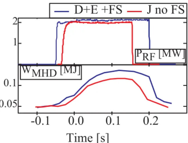
The voltage and power handling were unchanged (35 kV and 3 MW were achieved) and the loading was also very similar to previous operation. Comparing L-mode D(H) heated discharges, we found the heating effectiveness was reduced ~10% and the degradation is independent of plasma current and distance between plasma and antenna. The relative core plasma Cu density showed a strong correlation with shield-less antenna operation and power level. The likely source of the Cu is the screen-less antenna. In previous campaigns with Faraday screens on all antennas, the Cu observed in C-Mod was negligible. Furthermore, video images of the screen-less antenna showed strong visible emission near the middle of the antenna perhaps indicating the Cu source location. In H-mode D(H) heated discharges, the heating effectiveness degradation was 15-20%, larger than in L-mode[28]. Another important, perhaps positive, observation is the lack of damage to the protection tiles. No melt damage was found at corner tiles where, during previous operation, melting had occurred. This suggests the Faraday screen is influencing the formation of localized hot spots on the antenna. The plasma performance degradation without a screen could be largely attributed to influx of Cu with RF power where the Cu influx has both direct and indirect consequences. First, the Cu contribution to overall radiated power is approximately 30% of the injected RF power. Second, in H-mode the Cu line emission is localized to the pedestal, potentially lowering the edge temperature pedestal and overall confinement. To improve screen-less operation, a reduction in the Cu influx with RF is required and could be tested by modifying the antenna design to minimize the sheath effects.
5.0 Antenna Operation at High Neutral Pressure
In addition to impurity production, poor voltage handling itself can limit antenna performance. On C-Mod, high density discharges can yield neutral pressures at which antenna operation is inhibited. The 2-strap antenna limit is ~1 mTorr and the 4-strap antenna limit is ~0.4 mTorr in standard plasma discharges. An example of the phenomena is shown in Figure 7 where the neutral pressure rises to 0.4 mTorr and the antenna power trips and fails to restart. This neutral pressure limit may be similar to phenomena associated with
1
2
PRF [MW]
0.05
0.1
WMHD [MJ]
-0.1
0.0
0.1
0.2
D+E +FS
Time [s]
J no FS
Figure 6: Stored energy is lower for the J antenna
without a Faraday screen (FS) compared to D+E antennas with a Faraday screen.
antenna ELM (edge localized mode) interactions. In the Coaxial Multpactor Experiment (CMX), various conditions and geometries were investigated to measure their susceptibility to multipactor[39]. The results indicated that a coaxial transmission line is more susceptible to multipactor than strip line with similar electrode spacing. Furthermore, CMX results showed the presence of multipactor can cause a discharge at neutral pressures two orders of magnitude below the Paschen breakdown limit. In the presence of a B-field, the neutral pressure at which the discharge is initiated was further reduced
on both CMX and C-Mod. Experiments on the C-Mod ICRF antennas where the antennas were operated into the tokamak backfilled with D2 gas with and without a magnetic field found the discharge onset to be similar to the observed operational antenna neutral pressure limits with a ~0.1 T field present, suggesting the neutral pressure limit is a result of an induced discharge.[40] For magnetic fields accessible with CMX (<0.1 T), we found that the pressure at which the discharge was initiated decreased with increasing magnetic field. However, the C-Mod experiments showed the neutral pressure limit was the same for 0.1 T and 5.4 T. This suggests once the magnetic field is ~0.1 T the magnetic field does not result in further degradation in the neutral pressure limit. From simulations, the magnetic field does not modify the electron distribution function nor does it significantly modify the particle trajectory sufficiently to account for the decrease in discharge on pressure through increased ionization probability. The simulations show that the magnetic field does alter the trajectories in that only electrons with paths along the magnetic field can multipactor in a coaxial geometry. Further CMX experiments indicated that this discharge can be eliminated by using materials with a secondary electron coefficient less than unity for all energies. We found roughening a copper surface by grit blasting using 50 µm Al2O3 was sufficient to achieve the desired decrease in secondary emission in the CMX device.
6.0 Acknowledgements
One of the authors, S. Wukitch, would like to acknowledge the Peter Koert for insightful discussions regarding the details of antenna modeling; Paul Schmit and Gabriel Becerra for continuing the CMX work. This work is support by Department of Energy Coop. Agreement DE-FC02-99ER54512.
References
[1] I.H. Hutchinson, R. Boivin, F. Bombarda et al., Phys. Plasmas 1 (1994) 1511. [2] Y. Takase, S.N. Golovato, M. Porkolab, K. Bajwa, H. Becker, and D. Caldwell, 14th
Symp. on Fusion Eng., San Diego, 1992, (IEEE, Piscataway, NJ, 1992), p. 118. [3] S.J. Wukitch et al., Plasma Phys. Control. Fusion 46 (2004) 1479.
[4] L. L. Lao et al., Nucl Fusion 25 (1985) 1611. [5] R.L. Boivin et al., Rev. Sci. Instrum. 70, 260 (1999). [6] J. A. Goetz et al., J. Nucl. Mater. 220, 971 (1995).
1 2 3 PRF (MW) 0.5 0.6 0.7 0.8 0.9 0 0.2 0.4 0.6 0.8 Pneutral (mTorr) 1050526001 Time (s) J antenna
Neutral Pressure Limit
Figure 7: Example of so-called neutral pressure
[7] J.A. Goetz et al., Phys. Plasmas 3, 1908 (1996).
[8] H. Ohkawa, Master’s thesis, Massachusetts Institute of Technology, PSFC/RR-97-11 (1997).
[9] B. Lipschultz et al., Phys. Plasmas 13 (2006) 056117. [10] R.A. Hulse, Nuclear Technology/Fusion 3 (1983) 259. [11] J.E. Rice et al., Physics of Plasma 4 (1997) 1605.
[12] D.E. Post et al., Atomic Data and Nuclear Data Tables 20 (1977) 397. [13] K.B. Fournier et al., Nuclear Fusion 37 (1997) 825.
[14] K.B. Fournier et al., Nuclear Fusion 38 (1998) 639.
[15] P.J. O’Shea and A.E. Hubbard, Proc. of the 9th Joint Workshop on Electron Cyclotron Emission and Electron Cyclotron Heating, Borrego Springs, CA, (World Scientific, 1995) p. 393.
[16 ] J.W. Heard et al., Rev. Sci. Instrum. 70, 1011 (1999). [17] J.W. Hughes et al., Rev. Sci. Instrum. 72, 1107 (2001). [18] J.W. Hughes et al., Rev. Sci. Instrum. 74, 1667 (2003).
[19 ] T.E. Tutt, Master’s thesis, Massachusetts Institute of Technology, PSFC/RR-99-11 (1999).
[20] B. Lipschultz et al., this conference.
[21] J. Myra, 16th Topical Conference on RF Power in Plasmas, AIP Conf. Proceedings
787 (2006) 3.
[22] C.E. Harris et al., Fusion Tech. 30 (1996) 1.
[23] B. Lipschultz et al., Phys. Plasmas 13 (2006) 056117.
[24 ] S.J. Wukitch et al., Plasma Physics Control. Fusion 46 (2004) 1479. [25 ] B. Lipschultz et al., accepted to J. Nuclear Materials (2006).
[26] B. Lipschultz, et al., Nuclear Fusion 41 (2001) 585.
[27] S.J. Wukitch et al., Plasma Physics Control. Fusion 46 (2004) 1479. [28] S.J. Wukitch et al., accepted to J. Nuclear Materials (2006).
[29] J.R. Myra, D.A. D’Ippolito, and M. Bures, Phys. Plasmas 1 (1994) 2890. [30] M. Porkolab, Stix Symposium, Princeton, 1992, PSFC/RR-93-19. [31] P. Ryan et al., Nuclear Fusion (1994).
[32] M. Bures et al., Nucl. Fusion 30 (1990) 251. [33] M. Bures et al., Nuclear Fusion 32 (1992) 1139.
[34] R. Van Nieuwenhove et al., Nucl. Fusion 31 (1991) 1770. [35] R. Van Nieuwenhove et al., Nucl. Fusion 32 (1992) 1913. [36] J. Sorensen et al., Nucl. Fusion 33 (1993) 915.
[37] J-M Noterdaeme et al., 16th Inter. Conf. on Fusion Energy (IAEA(Vienna), Montreal, 1997), p. 335.
[38] R.I. Pinsker et al., 11th Topical Conference on RF Power in Plasmas (AIP, Woodbury), p. 43.
[39] T. Graves et al., Rev. Sci. Instruments 77 (2006) 014701. [40] T. Graves et al., J. Vac. Sci. Technology A 24 (2006) 512.