HAL Id: hal-00303882
https://hal.archives-ouvertes.fr/hal-00303882
Submitted on 23 Feb 2006HAL is a multi-disciplinary open access
archive for the deposit and dissemination of sci-entific research documents, whether they are pub-lished or not. The documents may come from teaching and research institutions in France or abroad, or from public or private research centers.
L’archive ouverte pluridisciplinaire HAL, est destinée au dépôt et à la diffusion de documents scientifiques de niveau recherche, publiés ou non, émanant des établissements d’enseignement et de recherche français ou étrangers, des laboratoires publics ou privés.
Some ice nucleation characteristics of Asian and Saharan
desert dust
P. R. Field, O. Möhler, P. Connolly, M. Krämer, R. Cotton, A. J. Heymsfield,
H. Saathoff, M. Schnaiter
To cite this version:
P. R. Field, O. Möhler, P. Connolly, M. Krämer, R. Cotton, et al.. Some ice nucleation character-istics of Asian and Saharan desert dust. Atmospheric Chemistry and Physics Discussions, European Geosciences Union, 2006, 6 (1), pp.1509-1537. �hal-00303882�
ACPD
6, 1509–1537, 2006 Ice nucleation on desert dust P. R. Field et al. Title Page Abstract Introduction Conclusions References Tables Figures J I J I Back CloseFull Screen / Esc
Printer-friendly Version Interactive Discussion
EGU
Atmos. Chem. Phys. Discuss., 6, 1509–1537, 2006 www.atmos-chem-phys-discuss.net/6/1509/2006/ © Author(s) 2006. This work is licensed
under a Creative Commons License.
Atmospheric Chemistry and Physics Discussions
Some ice nucleation characteristics of
Asian and Saharan desert dust
P. R. Field1,5, O. M ¨ohler2, P. Connolly3, M. Kr ¨amer4, R. Cotton1, A. J. Heymsfield5, H. Saathoff2, and M. Schnaiter2
1Met Office, OBR (Observations Based Research), UK 2
Forschungszentrum Karlsruhe, Institute for Meteorology and Climate Research (IMK-AAF), Germany
3
University of Manchester, School of Earth, Atmospheric and Environmental Sciences, UK
4
Forschungszentrum J ¨ulich, Institute of Chemistry and Dynamics of the Geosphere (ICG-I), Germany
5
NCAR, MMM (Mesoscale and Microscale Meteorology), USA
Received: 5 December 2005 – Accepted: 20 December 2005 – Published: 23 February 2006 Correspondence to: P. R. Field ([email protected])
ACPD
6, 1509–1537, 2006 Ice nucleation on desert dust P. R. Field et al. Title Page Abstract Introduction Conclusions References Tables Figures J I J I Back CloseFull Screen / Esc
Printer-friendly Version Interactive Discussion
EGU
Abstract
The large (7 m×4 m cylinder) AIDA (Aerosol Interactions and Dynamics in the Atmo-sphere) cloud chamber facility at Forschungszentrum, Karlsruhe, Germany was used to test the ice nucleating ability of two desert dust samples from the Sahara and Asia. At temperatures warmer than −40◦C droplets were formed before ice crystals formed, 5
there was no deposition nucleation observed. At temperatures colder than −40◦C both dust samples exhibited dual nucleation events that were observed during the same ex-pansion experiment. The primary nucleation event occurred at ice saturation ratios of 1.1 to 1.3 and is likely to be a deposition nucleation mode. The secondary nucleation event occurred at ice saturation ratios between 1.35 and 1.5. It is unclear whether this 10
ice nucleation event is via a further deposition mode or a condensation mode. The activated fractions of desert dust ranged from ∼5–10% at −20◦C to 20–40% at tem-peratures colder than −40◦C. There was no obvious difference between the nucleation behaviour of the two dust samples.
1 Introduction
15
The role of desert dust in ice nucleation has recently been characterized in the Caribbean during the CRYSTAL-FACE (Cirrus Regional Study of Tropical Anvils and Cirrus Layers – Florida Area Cirrus Experiment) campaign when Saharan dust ad-vected across the Atlantic into the field area (Sassen et al., 2003; DeMott et al., 2003; Cziczo et al., 2004). Desert dust is known to act as good deposition nuclei (e.g. Isono, 20
1953; Roberts and Hallett, 1968) but other nucleating properties associated with desert dust are not well characterized. If desertification continues to increase then the role of dust on ice microphysics will gain in importance and will need to be explicitly accounted for in weather and climate models. As computer models become more sophisticated they will include global sources and sinks of different aerosol species and will therefore 25
ACPD
6, 1509–1537, 2006 Ice nucleation on desert dust P. R. Field et al. Title Page Abstract Introduction Conclusions References Tables Figures J I J I Back CloseFull Screen / Esc
Printer-friendly Version Interactive Discussion
EGU
scale cloud systems.
DeMott et al. (2003) reported on ice nuclei measurements in a Saharan dust plume observed during the CRYSTAL-FACE experiment (Jensen et al., 2004). They found that at −36.5◦C and a supersaturation with respect to ice of 23% they observed ∼1 cm−3 ice nuclei concentrations. These conditions are below water saturation so these obser-5
vations represent the concentration of deposition nuclei. Coincident aerosol concen-trations for sizes greater than 0.5 µm were ∼10 cm−3. It is likely that the concentrations were higher, but even assuming background aerosol concentrations of 10 cm−3 gives an upper limit for ice nucleation efficiency of 0.1. During the same campaign Sassen et al. (2003) presented evidence suggesting that altocumulus clouds (−5 to −8◦C) were 10
being glaciated through interaction with the Saharan dust and Cziczo et al. (2004) showed that mineral dust was the dominant residue during the event found after in-situ ice particles were captured and evapourated. Analysis of CVI residuals (Targino et al., 2005) from the INTACC experiment (Field et al., 2001) showed that mineral dust is more prevalent in the cases where heterogeneous ice nucleation was observed to be 15
active.
Recently, Zuberi et al. (2002) looked at the formation of ice on aqueous droplets ((NH4)2SO4-H2O, 10–50 µm in size) containing dust particles. They found that for sig-nificant mass fractions of dust (>27%) that the droplets froze at much lower saturations than would be expected for homogeneous freezing of a droplet without any dust inclu-20
sion. Similarly, Hung et al. (2003) showed that mineral dust inclusions increased the temperature at which ice nucleation occurs.
Previous laboratory work on the ice nucleating ability of kaolinite has been carried out by Roberts and Hallett (1968). They found that for freshly prepared samples that supersaturations with respect to ice of 20% at temperatures colder than −18◦C were 25
required for the kaolinite to act as an ice nuclei. Following the formation of ice they raised the temperature slightly to drive off the ice and repeated the experiment. They found that kaolinite particles that had previously formed ice crystals now activated at 10% supersaturation with respect to ice.
ACPD
6, 1509–1537, 2006 Ice nucleation on desert dust P. R. Field et al. Title Page Abstract Introduction Conclusions References Tables Figures J I J I Back CloseFull Screen / Esc
Printer-friendly Version Interactive Discussion
EGU
These results suggest that the role of desert dust in the evolution of clouds and precipitation may be important and provided motivation for the present study reported here and in a companion paper (M ¨ohler et al., 2005). In this paper we report on a series of laboratory experiments carried out at the AIDA cloud and aerosol chamber facility in which two desert dust samples were tested under realistic atmospheric conditions and 5
in relatively large numbers. In Sect. 2 the basic experimental procedure is outlined. In Sect. 3 the dust samples are described. In Sect. 4 the instrumentation used is described. Section 5 is a presentation of the results and Sects. 6 and 7, respectively, contain the discussion and conclusions.
2 Experimental procedure
10
The cylindrical AIDA aerosol vessel is 7m high and 4m in diameter. The aerosol vessel is located within a larger chamber that acts as a thermal buffer and provides control of the initial temperature within the aerosol vessel. A fan within the aerosol vessel ensures well mixed conditions with sample temperatures within the volume agreeing to ±0.3 K.
15
Ice nucleation experiments are started just below ice saturation inside the aerosol chamber. This is achieved by cooling the chamber to 273 K, evacuating the vessel to 0.01 mb, flushing twice with synthetic air, adding water vapour and filling the vessel to atmospheric pressure with synthetic air. Finally, the vessel is cooled to the starting temperature of the experiment.
20
To simulate the adiabatic cooling of rising air parcels the pressure within the chamber is reduced with a rate controllable mechanical pump from 1000 hPa to 800 hPa over typical pumping periods of 5 min. Mean cooling rates (close to the time of nucleation) for the experiments presented here were typically 1–2 K min−1 that is equivalent to ascent speeds of 1–3 m s−1. The cooling in the aerosol vessel is not purely adiabatic: 25
the aerosol vessel wall temperatures remain approximately constant throughout the expansion and as a consequence there is a heat flux from the vessel wall into the
ACPD
6, 1509–1537, 2006 Ice nucleation on desert dust P. R. Field et al. Title Page Abstract Introduction Conclusions References Tables Figures J I J I Back CloseFull Screen / Esc
Printer-friendly Version Interactive Discussion
EGU
chamber. Similarly, during the cooling the vapour pressure above the ice on the wall is greater than the vapour pressure in the chamber and a vapour flux into the chamber also occurs.
Before the candidate aerosol is added to the chamber a control run is made with the background conditions in the chamber. Once complete the candidate aerosol is 5
added and then characterized with standard aerosol sampling intrumentation. Several expansions are carried out on the same candidate aerosol sample at different pump speeds (cooling rates) throughout the course of a day. Typically, during each series of 3 or 4 expansions, the first expansion was done at a higher cooling rate than the subsequent expansions. More details about the AIDA chamber and the experimental 10
procedures can be found in M ¨ohler et al. (2003, 2005).
3 Dust samples
Two surface samples of desert dust obtained from Asia (AD1) and the Sahara (SD2) were used. X-ray fluorescence analysis indicated that the Asian and Saharan dust samples were rich in silicon and calcium oxides, respectively. M ¨ohler et al. (2005) 15
gives more information concerning the results of X-ray analysis and aerosol distribu-tions. The samples were dry re-dispersed producing aerosol distributions with a size range between 0.1 and 2 µm with mode diameters between 0.3 and 0.5 µm. Prior to the experiment the samples were stored in clean conditions and did not undergo any heating or crushing.
20
4 Instrumentation
The AIDA chamber is populated with many instruments (see M ¨ohler et al., 2003, 2005), but we will briefly describe only the instrumentation referred to in this paper.
The temperature of the gas and wall of the chamber is measured at multiple loca-tions with platinum resistance thermometers and thermocouples. These values are 25
ACPD
6, 1509–1537, 2006 Ice nucleation on desert dust P. R. Field et al. Title Page Abstract Introduction Conclusions References Tables Figures J I J I Back CloseFull Screen / Esc
Printer-friendly Version Interactive Discussion
EGU
combined and an average gas temperature accurate to ±0.3 K is computed. Pres-sure is meaPres-sured with high precision Baratron sensors (MKS, Munich). An in situ multi-reflection path tunable diode laser absorption spectrometer directly measures the the water vapour concentration in the chamber volume. The TDL water vapour concentration is scaled to match a cryogenically cooled mirror hygrometer (LX373, 5
MBW,Switzerland) that is accurate to better than ±0.1 K during the expansion phase before any condensate appears. The estimated error in the TDL water vapour concen-tration is ±5%. This device is located two thirds of the way up the chamber. The sample air for the humidity sensors is obtained through a 8 mm diameter inlet heated to 30◦C located near the top of the chamber. Once particles are produced they will be ingested 10
and evapourated as they enter the humidity measurement system. This effect results in the humidity measurement containing some contribution from the condensed water content. As the particles grow larger their collection efficiency by the humidity system decreases and the contribution from particles is difficult to quantify. Hence when con-densed water contents are high the total water measurement can become unreliable. 15
Combining the uncertainties in the temperature and water vapour concentration pro-vides an estimate of the uncertainty in the 1-s humidity measurement of ±6% for the temperature and humidity range considered here.
Particles are detected and measured with the Small Ice Detector (SID) and Cloud Particle Imager (CPI: Stratton Park Engineering Company, SPEC Inc). These two 20
probes were primarily designed to sample particles from aircraft, but can be used in the laboratory. Aerosol particles in the size range 0.01 to 10 µm are measured with a combination of a scanning mobility particle sizer (SMPS, TSI), an aerodynamic particle spectrometer (APS, TSI) and a CPC3010 (TSI) optical particle counter. In some cases the aerosol data was not available and so we made use of the Welas probe (Palas 25
Aerosol Technology, Germany).
The hypothesis that liquid droplets are spherical and ice crystals are not spherical is the basis of the phase determination method used by the SID probe. The SID is a laser scattering device that can count and size spherical particles between 1 and 35 µm
ACPD
6, 1509–1537, 2006 Ice nucleation on desert dust P. R. Field et al. Title Page Abstract Introduction Conclusions References Tables Figures J I J I Back CloseFull Screen / Esc
Printer-friendly Version Interactive Discussion
EGU
(diameter) and count non-spherical particles. The probe uses six detectors arranged azimuthally at a forward scattering angle of 30◦, with a seventh detector mounted at the forward scattering angle. One of the six 30◦ detectors has an iris fitted to allow it to define a 400×800 µm ellipse on the scattering laser. When light was detected by this detector and one other detector, a particle was known to be in the sample 5
volume and the detector responses were recorded. By comparing the responses of the azimuthally arranged detectors an “asphericity factor” (Af ) could be obtained for each particle measured that ranges from 0 for spherical particles to 100 for very non-spherical particles (see Hirst et al., 2001, for more details). The five 30◦detectors that were not stopped down with the iris were used to compute Af using:
10 Af = k q P5 i=1(< E > −Ei) 2 < E > , (1)
where k is a constant (=22.361) set to place Af in the range 0–100, Ei are the detector values and <E > is the mean of Ei. In practice, noise and differences between the detectors mean that the spherical droplets that should give Af=0 will in general produce non-zero values. Single particles must therefore be differentiated from ice by using a 15
threshold value for the asphericity. Using a threshold can lead to some non-spherical particles being classed as spherical and vice-versa (see Field et al., 2004). The SID probe sampled from the chamber with a flow speed of ∼5 m s−1 (∼1 cm3sampled per second). This flow speed is very different from aircraft speeds so the instrument used different calibration constants for sizing. Particle sizing from this instrument assumes 20
that the particle is spherical. Therefore, non-spherical particles will be incorrectly sized, but this “spherical size” can still be used qualitatively to assess if ice particles are growing.
The CPI is a 2-D imaging probe designed to take high resolution images of cloud ice crystals and large droplets. It has two particle detection lasers which intercept at the 25
probes sample area (located within the probes air sampling tube at the focal plane of an objective lens; the images are magnified using a galilean telescope arrangement)
ACPD
6, 1509–1537, 2006 Ice nucleation on desert dust P. R. Field et al. Title Page Abstract Introduction Conclusions References Tables Figures J I J I Back CloseFull Screen / Esc
Printer-friendly Version Interactive Discussion
EGU
and fall onto a photomultiplier dump spot. Once particles are detected with the particle detection lasers/photomultipliers a high power, 20 ns pulsed laser is armed which is directed through the sample area, falling onto a charge coupled device (CCD) cam-era, which consequently images the shadow of the particle. Since the distance of the particle from the object plane is comparable to the size of the particle, the images 5
are well described by the Fresnel-Kirchhoff diffraction theory, which is the basis for the correction of probe sample volume and particle size. The CPI is able to sample par-ticles within the size range of approximately 10 to 2000 microns. Sampling efficiency decreases as particle size decreases from 20 microns as a threshold shadow depth is required for detection. The depth of field of the particle is constrained so that the 10
images are not in poor focus.The limitations of the probe are discussed in Connolly et al. (2005). Image processing techniques are applied to the particle images, so that particles can be sized, and classified into droplets, or numerous ice particle habits. When particle size increases above 400 µm, the sampling efficiency drops off gradu-ally due to the fact that the overlapping cross section of particles with the sample area 15
decreases.
The Welas particle probe uses white light scattering collected at 90±12◦ scattering angle from a sample volume defined by an apertured light source to measure parti-cles in the size range 0.8 to 46 µm (for water droplets). The flow speed used for this instrument was 5 l min−1.
20
5 Results
5.1 Time series
We present four time series to demonstrate the ice nucleation behavior of the dust samples at different temperatures. Three examples result from using the Asian dust sample and one from the Saharan dust sample. The features of the ice nucleation that 25
ACPD
6, 1509–1537, 2006 Ice nucleation on desert dust P. R. Field et al. Title Page Abstract Introduction Conclusions References Tables Figures J I J I Back CloseFull Screen / Esc
Printer-friendly Version Interactive Discussion
EGU
dust samples at the same temperature.
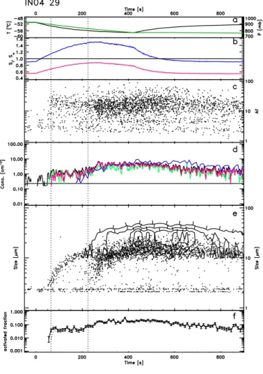
Each time series figure comprises of 6 panels showing 1-s data as a function of time since the start of pumping. Panel (a) shows the pressure forcing and temperature change imposed in the AIDA cloud chamber. Panel (b) gives the saturation ratio with respect to water and ice throughout the experiment. Panel (c) is a plot of the SID as-5
phericity parameter, Af , each point represents a single particle measurement. In panel (d) various concentrations are depicted (5-s smoothing): The total SID concentration, the concentration of SID particles with Af >12 (non-spherical particles), the concentra-tion of SID particles with “spherical size” >3 µm and the CPI concentraconcentra-tion. Panel (e) shows single particle measurements of SID particle “spherical size” and a contour plot 10
of the CPI size distribution to provide the reader with a qualitative indication of when larger ice particles are present. Finally, panel (f) shows the activated fraction of ice particles defined by the concentration of particles with 10-s binned Af >12 compared to the instantaneous aerosol concentration defined by the (initial aerosol concentration × pressure)/(initial pressure). Running vertically throughout the figure are dotted lines 15
that indicate when the fraction activated nominally exceeds 0.5% and 8%. Ice concen-trations were determined by the SID concentration of non-spherical particles (Af >12). Because the determination of particle sphericity can lead some particles to be classi-fied as spherical, the concentration of ice crystals using this criteria will be underesti-mated. By comparing the activated fraction derived from using shape and size towards 20
the end of each experiment when the humidity is below water saturation but saturated with respect to ice and by intercomparison with other optical particle counters we find that the using the Af >12 criteria the activated fraction is underestimated by a factor of 1.6 compared to the fraction greater than 3 µm. Consequently we have multiplied the
Af >12 activated fraction by 1.4 and this is shown in panel (f). We also note here that
25
there may be some time delay between ice particles nucleating and their subsequent detection with SID. M ¨ohler et al. (2005) have attempted to estimate this delay by invok-ing a simple growth model. Such an approach is more difficult to apply when we are considering the shape as well as the size of the particles and may not be necessary
ACPD
6, 1509–1537, 2006 Ice nucleation on desert dust P. R. Field et al. Title Page Abstract Introduction Conclusions References Tables Figures J I J I Back CloseFull Screen / Esc
Printer-friendly Version Interactive Discussion
EGU
at the relatively warm temperatures considered here: M ¨ohler et al. (2005) estimate a delay of 4 s for the growth to ∼1 µm at −50◦C, the coldest temperatures presented in this paper. Nevertheless, this difference in approach to estimating the onset of nucle-ation leads to slight differences in conditions at which the nucleation is observed, but still within the estimated experimental errors. Various parameters relating to the ice 5
nucleation events are given in Table 1. Example CPI imagery from these experiments can be seen in Fig. 5.
Figure 1 shows one example from the coldest series of ice nucleation events sam-pled with the SID probe. Run 29 (AD1) starts at −51◦C and is cooled to −57◦C over ∼400 s. Around 0s the background aerosol that can be detected by SID can be seen in 10
panel (e). This aerosol generally has a “spherical size” <3 µm for all of the experiments and we use this as a threshold size between activated particles and aerosol. At 50 s panel (e) shows a rapid increase in the size of particles, panel (d) indicates increases in SID concentrations and panel (c) shows the abrupt appearance of particles with Af values greater than 12. At 250 s there is another burst of ice particle production visible 15
in panel (e) as a second branch of increasing SID particle size. This is accompanied by a step increase in SID concentrations shown in panel (d). The particle concentra-tions then remain fairly constant until the humidity falls below ice saturation. The two ice nucleation events occur at supersaturation with respect to ice of 10% and 50% and activate ∼5% and ∼30% of the aerosol, respectively. CPI imagery for this experiment 20
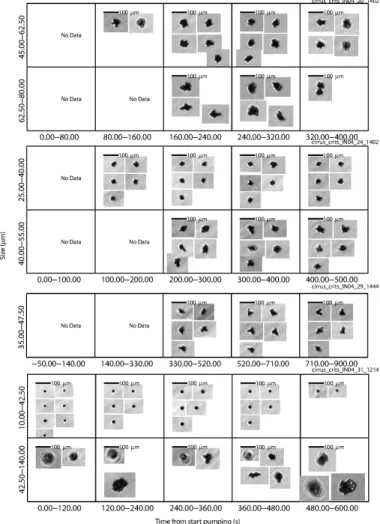
in Fig. 5 shows rosette-like habits.
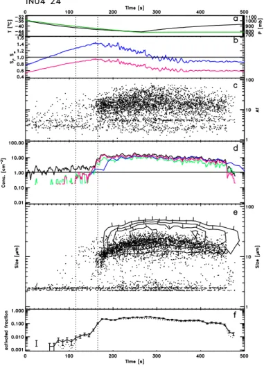
Figure 2 is for run 24 (AD1) which began at −36◦C and cooled to −44◦C after 270 s. As in the previous case it is possible to discern two ice nucleation events. One oc-curs at 70 s marked by the growth of a few ice particles in panel (e) and then a more obvious second event at 150 s that is close to water saturation (∼95%). Variability of 25
the humidity and temperature fields within the chamber could result in regions at water saturation. If so, then any droplets produced were either not sampled by the SID or smaller than ∼3 µm in diameter This figure exemplifies the difficulties in determining the onset of ice nucleation. The CPI concentration in panel (d) supports the
sugges-ACPD
6, 1509–1537, 2006 Ice nucleation on desert dust P. R. Field et al. Title Page Abstract Introduction Conclusions References Tables Figures J I J I Back CloseFull Screen / Esc
Printer-friendly Version Interactive Discussion
EGU
tion that there is a nucleation event before the one at 150 s, identified by the growth of particles measured by SID. As in the previous example the activated fraction of aerosol from the primary and secondary nucleation events is ∼5% and ∼30%. CPI imagery for this experiment in Fig. 5 again shows rosette-like habits.
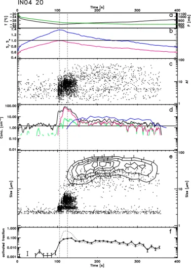
Figure 3 is from run 20 (AD1) and appears different to the previous two examples. 5
The run began at −23◦C and was cooled to −32◦C over 110 s. In this case it can be seen that at 100 s there is a rapid production of large numbers of particles (panel d). Referring to the asphericity parameter in panel (c) suggests that from 100 s to 150 s the cloud is dominated by water droplets (asphericity values <12). Looking at the concentration of non-spherical particles and CPI concentration (panel d) as well as the 10
particle sizes (panel e) indicates that ice particles were present almost coincidently with the formation of droplets, but not before. This suggests that the dominant ice nucleation mode in this case is an immersion or condensation mechanism and activated about 10% of the aerosol (panel f). Again, CPI imagery for this experiment in Fig. 5 shows rosette-like habits, although the coldest temperature attained during this experiment 15
was only −32◦C, therefore they may be some other type of polycrystal habit. Although it should be noted that habit discrimination using the CPI is difficult for particles of this size.
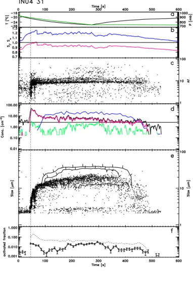
Figure 4 results from run 31 which is part of the series of warmest runs presented here and uses the Saharan dust sample (SD2). In this case the cooling is from −19◦C 20
to −26◦C in 280 s. Panel (e) shows the growth of particles starting at 40 s into the run. Panel (c) suggests that water droplets are present throughout the run until 470 s. One unusual aspect of this series of runs is that the droplet concentration shows a peak near the beginning of the run and then falls to a plateau later. Comparison with the Welas instrument (M ¨ohler et al., 2005) suggests that the SID is not seeing a large fraction of 25
the water droplets. One suggestion for this discrepancy is that some water droplets are evapourating at these warm temperatures as they travel down the SID sample tube from the AIDA chamber. Nevertheless, we still observe that ice is formed at the same time as the droplets. Evidence for this comes from the CPI imagery which shows low
ACPD
6, 1509–1537, 2006 Ice nucleation on desert dust P. R. Field et al. Title Page Abstract Introduction Conclusions References Tables Figures J I J I Back CloseFull Screen / Esc
Printer-friendly Version Interactive Discussion
EGU
concentrations of ice particles. In this series of experiments (30, 31, 32), the aerosol concentrations were not available. Instead we used the peak droplet concentration from the Welas probe as experiments 18–21 showed that all of the aerosol became activated under the forcing conditions applied. CPI imagery in Fig. 5 for this experiment appears to show the coexistence of large droplets with irregular shaped ice crystals. A 5
high resolution image of the particle shown in the 480–600 s 52–87 µm panel suggests that this is a two crystal aggregate.
5.2 Synthesis
As mentioned above we have identified when the activated fraction of aerosol exceeded 0.5% and 8%. In practice, it was found that this choice of thresholds readily located the 10
beginning of both the first and second nucleation event when two events were obvious. The results of this analysis are shown in Figs. 6 and 7. Figure 6 indicates the relative humidity and temperature associated with the points exceeding the 0.5% and 8% ice fraction thresholds. Three regions have been identified on the plot. In region I droplets were observed to form at the same time or prior to the formation of ice. Region II 15
contains the primary nucleation events and region III contains the secondary events. Figure 7 shows the maximum fraction activated as a function of the temperature at which 0.5% were first activated.
6 Discussion
The experimental results can be divided into nucleation behavior at temperatures 20
warmer and colder than −40◦C. For temperatures warmer than −40◦C denoted by re-gion I in Fig. 6, the onset of ice nucleation activating aerosol fractions greater than 0.5% is coincident with the production of water droplets as the chamber reaches water saturation. Thus nucleation occurring in region I is via an immersion, condensation mode or homogeneous freezing for the experiments near −40◦C. Roberts and Hal-25
ACPD
6, 1509–1537, 2006 Ice nucleation on desert dust P. R. Field et al. Title Page Abstract Introduction Conclusions References Tables Figures J I J I Back CloseFull Screen / Esc
Printer-friendly Version Interactive Discussion
EGU
lett (1968) also observed, using a static diffusion chamber, that mineral dust samples warmer than a critical temperature needed to be brought to water saturation before ice formed. However, in their study, the coldest temperature for which this behavior was observed was −28◦C. The maximum activated fraction during the experiment for the region I nucleation events (Fig. 7) climbs by roughly a factor of 10 from 5 to 50% from 5
−20 to −40◦C, respectively. The high fractions seen for experiments 35–37 may result from additional ice forming via homogeneous nucleation at around −40◦C.
For temperatures colder than −40◦C Fig. 1 indicated that dual nucleation events were observed where ice formed at two distinct ice saturation ratios with a hiatus clearly vis-ible in the experiments where the pumping speed was slow enough to provide a low 10
cooling rate. This behavior was observed for both the Asian and Saharan desert dust samples. In Fig. 6, region II represents the primary activation during these experiments and region III marks the secondary nucleation event. In each of these series of experi-ments (22–25, 26–29, 40–42), the first expansion did not show a clear dual nucleation signature. However, the >0.5% and >8% activations for 22, 26, 40 appear to cluster 15
well with the results from the later experiments in each series. This suggests that if the first runs are carried out at slower pumping speeds then the dual nucleation will become apparent for the first expansion also – not because cooling rate is expected to affect the cooling rate (M¨ohler et al., 2005), but simply because this allows a longer temporal seperation between the nucleation events.
20
The activation of >0.5% of the aerosol occurs at an ice saturation ratio of 1.1 to 1.3. Archuleta et al. (2005) find that 1% of 200 nm asian mineral dust activates with a ice saturation ratio of ∼1.35. For the dust samples used here the mode in the particle size is approximately twice as large and bigger particles were also contained in the sam-ple tested (see Sect.3). The maximum activated fraction of desert dust following the 25
secondary nucleation event appears constant and in the 20–40% range. The primary nucleation mode typically activated <5% of the aerosol sample before the effects of the secondary mode became important. The ice saturation ratio at which the region II ice nucleation events occurred points to deposition nucleation as the likely formation
ACPD
6, 1509–1537, 2006 Ice nucleation on desert dust P. R. Field et al. Title Page Abstract Introduction Conclusions References Tables Figures J I J I Back CloseFull Screen / Esc
Printer-friendly Version Interactive Discussion
EGU
mechanism. The situation is not so clear for the secondary mode which activates >8% of the aerosol sample at ice saturation ratios between 1.35 and 1.5. These satura-tion ratios are close to what Zuberi et al. (2002) obtained for dust samples immersed in aqueous droplets ((NH4)2SO4-H2O, 10–50 µm in size). In this case, no droplets were observed, but Archuleta et al. (2005) suggest that condensation on hydrophillic 5
sites may be important at these temperatures and humidities. Therefore, it is unclear whether the secondary nucleation events (region III) represent a further deposition nu-cleation mode, or a condensation freezing mode facilitated by the presence of some soluble material on the surface of the aerosol. Future experiments should aim to anal-yse the ice crystal residuals in order to test these assertions.
10
The deposition nucleation (region II, activated fraction >0.5%) is only observed at temperatures colder than −40◦C and absent from the experiments performed at tem-peratures warmer than −40◦C. This is puzzling as supersaturations with respect to ice of in excess of 20% are attained before the droplets are activated at these warmer temperatures. One possible reason for this difference is that the nucleation rate falls 15
well below a threshold required for the production of sufficient ice crystals to be de-tected in this experimental setup. Other laboratory experiments using pure minerals (Roberts and Hallett, 1968; Bailey and Hallett, 2002) have shown that deposition nu-cleation readily occurred at temperatures warmer than −40◦C. This difference may be compositional, size related or a result of the SID detection thresholds. The SID sam-20
ples approximately 1 cm3 per second and the results are accumulated over 10s for estimating the activated fraction. This sets a realistic detection limit of ∼0.5 cm−3. In future experiments we will use higher sampling rates to try and resolve this apparent discrepancy.
Roberts and Hallett (1968) also reported that pre-activation of aerosol leads to ice 25
production at lower saturation ratios. We are unable to comment on this – from exam-ination of the starting aerosol concentration (Table 1) it is likely that all of the ice and hence ice nuclei sediment out during the course of each experiment.
ACPD
6, 1509–1537, 2006 Ice nucleation on desert dust P. R. Field et al. Title Page Abstract Introduction Conclusions References Tables Figures J I J I Back CloseFull Screen / Esc
Printer-friendly Version Interactive Discussion
EGU
experiments performed means that it is difficult to simply assign a bulk mineral dust sample with a nucleation rate. As Archuleta et al. (2005) show, there is at least a size dependence that needs to be taken into account. For this study it is possible that broadness of the size distribution of aerosol used contributes to the presence of the dual nucleation behavior, but it is also possible that mineralogically or chemically or 5
diverse subsets of particles are included in the dust samples tested here. Future work needs to include the capture and analysis of ice crystal residuals that form at different saturation ratios.
7 Conclusions
Two desert dust samples (modal diameter 300–500 nm) from the Sahara and Asia 10
were used in ice nucleation experiments between −20◦C and −60◦C in the AIDA cloud chamber. Very similar behaviour was observed for both dust samples. We observed dual nucleation events during single expansions at temperatures colder than −40◦C. The primary nucleation event is likely to be deposition nucleation, but the secondary event is either a further deposition mode exhibited by particles of different sizes or min-15
eralogical/chemical composition or a condensation mode facilitated by the presence of soluble material on the desert dust. At temperatures warmer than −40◦C droplets were formed before and at the same time as ice crystals were formed, presumably via and immersion or condensation ice nucleation mode and no deposition mode was ob-served. The maximum activated fraction of the desert dust sample forming ice varied 20
from ∼5–10% at −20◦C to 20–40% at temperatures colder than −40◦C.
Acknowledgements. We gratefully acknowledge the support of AIDA staff members
R. Buschbacher, T. Chudy, E. Kranz, G. Scheurig and S. Vogt for support during the campaigns. We thank L. Schutz (Univ. Mainz, Germany) for supplying the Asian dust sample, K. Megahed for supplying the Saharan dust samples and C. Adelhelm (IMF I, Forschungszentrum Karlsruhe)
25
for XRF analysis of the mineral dust samples. We also thank E. Hirst (Univ. Hertfordshire, Eng-land) for making modifications to SID to allow its use at AIDA.
ACPD
6, 1509–1537, 2006 Ice nucleation on desert dust P. R. Field et al. Title Page Abstract Introduction Conclusions References Tables Figures J I J I Back CloseFull Screen / Esc
Printer-friendly Version Interactive Discussion
EGU
References
Archuleta, C. M., DeMott, P. J., and Kreidenweis, S. M.: Ice nucleation by surrogates for atmo-spheric mineral dust/sulfate particles at cirrus temperatures, Atmos. Chem. Phys., 5, 3391– 3436, 2005.
Bailey, M. and Hallett, J.: Nucleation effects on the habit of vapour grown ice crystals from −18
5
to −42 degrees C, Quart. J. Royal Met. Soc., 128, 1461–1483, 2002.
Cziczo, D. J., Murphy, D. M., Hudson, P. K., and Thomson, D. S.: Single particle measurements of the chemical composition of cirrus ice residue during CRYSTAL-FACE, J. Geophys. Res., 109(D4), art. no. D04201, doi:10.1029/2003JD003942, 2004.
DeMott, P. J., Sassen, K., Poellot, M. R., Baumgardner, D., Rogers, D. C., Brooks, S. D., Prenni,
10
A. J., and Kreidenweis, S. M.: African dust aerosols as atmospheric ice nuclei, Geophys. Res. Lett., 30(14), art. no. 1732, doi:10.1029/2003GL017410, 2003.
Field, P. R., Cotton, R. J., Noone, K., et al.: Ice nucleation in orographic wave clouds: Measure-ments made during INTACC, Quart. J. Royal Met. Soc., 127, 1493–1512, 2001.
Field, P. R., Hogan, R. J., Brown, P. R. A., Illingworth, A. J., Choularton, T. W., Kaye, P. H., Hirst,
15
E., and Greenaway, R.: Simultaneous radar and aircraft observations of mixed-phase cloud at the 100 m scale, Quart. J. Royal Met. Soc., 130, 1877–1904, 2004.
Hirst, E., Kaye, P. H., Greenaway, R. S., Field, P., and Johnson, D. W.: Discrimination of micrometre-sized ice and super-cooled droplets in mixed-phase cloud, Atmos. Env., 35, 33– 47, 2001.
20
Hung, H.-M., Malinowski, A., and Martin, S. T.: Kinetics of heterogeneous ice nucleation on the surfaces of mineral dust cores inserted into aqueous ammonium sulfate particles, J. Phys. Chem. A., 107, 1296–1306, 2003.
Isono, K., Komabayasi, M., and Ono, A.: The nature and origin of ice nuclei in the atmosphere, J. Meteor. Soc. Japan, 37, 211–233, 1959.
25
Jensen, E., Starr, D., and Toon, O. B.: Mission investigates tropical cirrus clouds, EOS, 85, 45–50, 2004.
M ¨ohler, O., Stetzer, O., Schaefers, S., Linke, C., Schnaiter, M., Tiede, R., Saathoff, H., Kramer, M., Mangold, A., Budz, P., Zink, P., Schreiner, J., Mauersberger, K., Haag, W., Karcher, B., and Schurath, U.: Experimental investigation of homogeneous freezing of sulphuric acid
30
particles in the aerosol chamber AIDA, Atmos. Chem. Phys., 3, 211–223, 2003.
ACPD
6, 1509–1537, 2006 Ice nucleation on desert dust P. R. Field et al. Title Page Abstract Introduction Conclusions References Tables Figures J I J I Back CloseFull Screen / Esc
Printer-friendly Version Interactive Discussion
EGU M., Mangold, A., and Heymsfield, A.: Efficiency of the deposition mode of ice nucleation on
mineral dust particles, Atmos. Chem. Phys. Discuss., 6, 1539–1577, 2006.
Roberts, P. and Hallett, J.: A laboratory study of the ice nucleating properties of some mineral particulates, Quart. J. Royal Met. Soc., 94, 25–34, 1968.
Sassen, K., DeMott, P. J., Prospero, J. M., and Poellot, M. R.: Saharan dust storms and indirect
5
aerosol effects on clouds: CRYSTAL-FACE results, Geophys. Res. Lett., 30(12), art. no. 1633, doi:10.1029/2003GL017371, 2003.
Targino, A. C., Krejci, R., Noone, K. J., and Glantz, P.: Single particle analysis of ice crystal residuals observed in orographic wave clouds over Scandinavia during INTACC experiment, Atmos. Chem. Phys. Discuss., 5, 8055–8090, 2005.
10
Zuberi, B., Bertram, A. K., Cassa, C. A., Molina, L. T., and Molina, M. J.: Heterogeneous nucleation of ice in (NH4)(2)SO4-H2O particles with mineral dust immersions, Geophys. Res. Lett., 29(10), art. no. 1504, doi:10.1029/2001GL014289, 2002.
ACPD
6, 1509–1537, 2006 Ice nucleation on desert dust P. R. Field et al. Title Page Abstract Introduction Conclusions References Tables Figures J I J I Back CloseFull Screen / Esc
Printer-friendly Version Interactive Discussion
EGU
Table 1. Ice nucleation exceeding active fraction thresholds of 0.5 and 8%.
>0.5% >8%
Exp Temperature Pressure Saturation Temperature Pressure Saturation Max. act. Initial aerosol Sample Ratio Ratio Fraction Concentration
C mb C mb cm−3 18 −29.4 829 1.30 0.0 0 0.00 0.09 215 AD1 19 −30.2 844 1.31 −31.4 806 1.31 0.14 152 AD1 20 −32.0 846 1.36 −31.8 836 1.28 0.11 105 AD1 21 −33.4 856 1.38 −33.5 838 1.32 0.11 75 AD1 22 −40.5 900 1.30 −42.2 845 1.38 0.15 139 AD1 23 −41.2 892 1.30 −42.6 839 1.42 0.17 94 AD1 24 −41.3 892 1.27 −42.7 855 1.39 0.33 68 AD1 25 −40.4 901 1.12 – – – 0.06 45 AD1 26 −52.7 972 1.17 −53.9 950 1.31 0.28 119 AD1 27 −53.4 958 1.22 −55.0 924 1.43 0.30 72 AD1 28 −53.0 963 1.14 −55.7 893 1.46 0.19 44 AD1 29 −53.2 953 1.14 −55.9 875 1.48 0.33 29 SD2 30 −21.6 951 1.22 – – – 0.06 353 SD2 31 −21.1 952 1.20 – – – 0.03 150 SD2 32 −19.7 973 1.03 – – – 0.08 24 SD2 35 −38.0 928 1.43 −38.3 921 1.46 0.20 153 SD2 36 −38.5 923 1.42 −38.8 915 1.41 0.45 88 SD2 37 −36.1 963 1.15 −38.7 907 1.42 0.69 38 SD2 40 −51.7 945 1.25 −53.1 917 1.41 0.20 107 SD2 41 −52.0 941 1.26 −53.6 899 1.46 0.21 64 SD2 42 −51.5 955 1.17 −53.9 895 1.50 0.36 39 SD2
ACPD
6, 1509–1537, 2006 Ice nucleation on desert dust P. R. Field et al. Title Page Abstract Introduction Conclusions References Tables Figures J I J I Back CloseFull Screen / Esc
Printer-friendly Version Interactive Discussion
EGU
ACPD
6, 1509–1537, 2006 Ice nucleation on desert dust P. R. Field et al. Title Page Abstract Introduction Conclusions References Tables Figures J I J I Back CloseFull Screen / Esc
Printer-friendly Version Interactive Discussion
EGU
Fig. 1. Experiment IN04 29. Panel (a) shows the pressure forcing (green) and temperature
change imposed in the AIDA cloud chamber (black). Panel(b) gives the saturation ratio with
respect to water (red) and ice (blue) throughout the experiment. Panel(c) is a plot of the SID
asphericity parameter, Af , each point represents a single particle measurement. In panel(d)
various concentrations are depicted (5-s smoothing): The total SID concentration (black), the concentration of SID particles with Af >12 (non-spherical particles, green), the concentration of SID particles with “spherical size” >3 µm (red) and the CPI concentration (blue). Panel(e)
shows single particle measurements of SID particle “spherical size” and a contour plot of the CPI size distribution (tickmarks indicate “downhill” direction). Panel(f) shows 10-s values of the
activated fraction of desert dust (see text). Poisson counting errors are also shown. The solid line is the derived from particle concentrations for which Af >12 (corrected, see text) and the dotted line is the for particles with sizes greater than 3 µm.
ACPD
6, 1509–1537, 2006 Ice nucleation on desert dust P. R. Field et al. Title Page Abstract Introduction Conclusions References Tables Figures J I J I Back CloseFull Screen / Esc
Printer-friendly Version Interactive Discussion
EGU
ACPD
6, 1509–1537, 2006 Ice nucleation on desert dust P. R. Field et al. Title Page Abstract Introduction Conclusions References Tables Figures J I J I Back CloseFull Screen / Esc
Printer-friendly Version Interactive Discussion
EGU
Fig. 2. Experiment IN04 24. Panel (a) shows the pressure forcing (green) and temperature
change imposed in the AIDA cloud chamber (black). Panel(b) gives the saturation ratio with
respect to water (red) and ice (blue) throughout the experiment. Panel(c) is a plot of the SID
asphericity parameter, Af , each point represents a single particle measurement. In panel(d)
various concentrations are depicted (5-s smoothing): The total SID concentration (black), the concentration of SID particles with Af >12 (non-spherical particles, green), the concentration of SID particles with “spherical size” >3 µm (red) and the CPI concentration (blue). Panel(e)
shows single particle measurements of SID particle “spherical size” and a contour plot of the CPI size distribution (tickmarks indicate “downhill” direction). Panel(f) shows 10-s values of the
activated fraction of desert dust (see text). Poisson counting errors are also shown. The solid line is the derived from particle concentrations for which Af >12 (corrected, see text) and the dotted line is the for particles with sizes greater than 3 µm.
ACPD
6, 1509–1537, 2006 Ice nucleation on desert dust P. R. Field et al. Title Page Abstract Introduction Conclusions References Tables Figures J I J I Back CloseFull Screen / Esc
Printer-friendly Version Interactive Discussion
EGU
ACPD
6, 1509–1537, 2006 Ice nucleation on desert dust P. R. Field et al. Title Page Abstract Introduction Conclusions References Tables Figures J I J I Back CloseFull Screen / Esc
Printer-friendly Version Interactive Discussion
EGU
Fig. 3. Experiment IN04 20. Panel (a) shows the pressure forcing (green) and temperature
change imposed in the AIDA cloud chamber (black). Panel(b) gives the saturation ratio with
respect to water (red) and ice (blue) throughout the experiment. Panel(c) is a plot of the SID
asphericity parameter, Af , each point represents a single particle measurement. In panel(d)
various concentrations are depicted (5-s smoothing): The total SID concentration (black), the concentration of SID particles with Af >12 (non-spherical particles, green), the concentration of SID particles with “spherical size” >3 µm (red) and the CPI concentration (blue). Panel(e)
shows single particle measurements of SID particle “spherical size” and a contour plot of the CPI size distribution (tickmarks indicate “downhill” direction). Panel(f) shows 10-s values of the
activated fraction of desert dust (see text). Poisson counting errors are also shown. The solid line is the derived from particle concentrations for which Af >12 (corrected, see text) and the dotted line is the for particles with sizes greater than 3 µm.
ACPD
6, 1509–1537, 2006 Ice nucleation on desert dust P. R. Field et al. Title Page Abstract Introduction Conclusions References Tables Figures J I J I Back CloseFull Screen / Esc
Printer-friendly Version Interactive Discussion
EGU
ACPD
6, 1509–1537, 2006 Ice nucleation on desert dust P. R. Field et al. Title Page Abstract Introduction Conclusions References Tables Figures J I J I Back CloseFull Screen / Esc
Printer-friendly Version Interactive Discussion
EGU
Fig. 4. Experiment IN04 31. Panel (a) shows the pressure forcing (green) and temperature
change imposed in the AIDA cloud chamber (black). Panel(b) gives the saturation ratio with
respect to water (red) and ice (blue) throughout the experiment. Panel(c) is a plot of the SID
asphericity parameter, Af , each point represents a single particle measurement. In panel(d)
various concentrations are depicted (5-s smoothing): The total SID concentration (black), the concentration of SID particles with Af >12 (non-spherical particles, green), the concentration of SID particles with “spherical size” >3 µm (red) and the CPI concentration (blue). Panel(e)
shows single particle measurements of SID particle “spherical size” and a contour plot of the CPI size distribution (tickmarks indicate “downhill” direction). Panel(f) shows 10-s values of the
activated fraction of desert dust (see text). Poisson counting errors are also shown. The solid line is the derived from particle concentrations for which Af >12 (corrected, see text) and the dotted line is the for particles with sizes greater than 3 µm.
ACPD
6, 1509–1537, 2006 Ice nucleation on desert dust P. R. Field et al. Title Page Abstract Introduction Conclusions References Tables Figures J I J I Back CloseFull Screen / Esc
Printer-friendly Version Interactive Discussion
EGU
Fig. 5. Example CPI imagery from the four experiments shown in Figs. 1–4. The x-axis
rep-resents time since pumping started and the values on the y-axis indicate the size range of particles considered.
ACPD
6, 1509–1537, 2006 Ice nucleation on desert dust P. R. Field et al. Title Page Abstract Introduction Conclusions References Tables Figures J I J I Back CloseFull Screen / Esc
Printer-friendly Version Interactive Discussion
EGU
Fig. 6. Plot shows the ice saturation ratio and temperature at which ice nucleation was
ob-served to begin. Open symbols are the results for the Asian desert dust sample (AD1), filled symbols are for the Saharan desert dust sample (SD2). The numbers adjacent to each symbol represent the experiment number (see Table 1). Downward pointing triangles denote when the fraction of aerosol forming ice crystals exceeded 0.5%. Upward pointing triangles denote when the fraction of aerosol forming ice crystals exceeded 8%. Circled symbols indicate when examination of the time series for the experiment clearly showed two distinct nucleation events.
ACPD
6, 1509–1537, 2006 Ice nucleation on desert dust P. R. Field et al. Title Page Abstract Introduction Conclusions References Tables Figures J I J I Back CloseFull Screen / Esc
Printer-friendly Version Interactive Discussion
EGU
Fig. 7. This plot shows the maximum fraction of aerosol (10-s) activated to form ice as a
func-tion of temperature when the fracfunc-tion exceeded 0.5%. Open symbols are the results for the Asian desert dust sample (AD1), filled symbols are for the Saharan desert dust sample (SD2). The numbers adjacent to each symbol represent the experiment number (see Table 1). Circles represent experiments where only a single nucleation event was observed. The triangles and squares represent experiments where two nucleation modes were observed during a single experiment.The dotted line nominally divides the nucleation events into immersion and depo-sition modes (see text). Circled symbols indicate when examination of the time series for the experiment clearly showed two distinct nucleation events.