HAL Id: tel-01124003
https://tel.archives-ouvertes.fr/tel-01124003
Submitted on 6 Mar 2015
HAL is a multi-disciplinary open access
archive for the deposit and dissemination of sci-entific research documents, whether they are pub-lished or not. The documents may come from teaching and research institutions in France or abroad, or from public or private research centers.
L’archive ouverte pluridisciplinaire HAL, est destinée au dépôt et à la diffusion de documents scientifiques de niveau recherche, publiés ou non, émanant des établissements d’enseignement et de recherche français ou étrangers, des laboratoires publics ou privés.
Model-based Synthesis of Distributed Real-time
Automotive Architectures
Ernest Woźniak
To cite this version:
Ernest Woźniak. Model-based Synthesis of Distributed Real-time Automotive Architectures. Embed-ded Systems. Université Paris Sud - Paris XI, 2014. English. �NNT : 2014PA112145�. �tel-01124003�
UNIVERSITÉ PARIS-SUD
ÉCOLE DOCTORALE INFORMATIQUE PARIS-SUD
Laboratoire de CEA Tech LIST
DISCIPLINE
:
InformatiqueTHÈSE DE DOCTORAT
soutenue le 07/07/2014 par
Ernest Wozniak
Model-based Synthesis of Distributed Real-time
Automotive Architectures
Directeur de thèse: Dr. Sébastien Gérard CEA Tech LIST
Co-directeur de thèse: Dr. Chokri Mraidha CEA Tech LIST
Composition du jury
Président du jury : Burkhart Wolff Professeur (Université Paris-Sud, CNRS)
Rapporteur : Maryline Chetto Professeur (Université de Nantes, IRCCyN Research Institute)
Rapporteur : Martin Törngren Professeur (KTH Royal Institute of Technology)
Examinateur : Claire Pagetti Ingénieur-Chercheur (ONERA)
iii
Model-based Synthesis of Distributed Real-time Automotive Architectures
Copyright © 2014 by
iv
ACKNOWLEDGEMENTS
First I wish to thank my supervisor Dr. Sébastien Gérard. He guided me into the domain of modeling and provided almost unlimited resources and support for my research. It was a great pleasure for me to work with Sébastien Gérard. His professionalism, friendliness and openness to other people let me to simply enjoy my work under his supervision.
I am very grateful to my co-supervisor, Dr. Chokri Mraidha for his guidance throughout my entire PhD work from the very beginning where he helped me to arrange my arrival to the CEA Tech LIST institute till the very end where he dealt with all the necessary preparations to organize my defense. I am especially thankful for all his reviews done on my papers and thesis report as well as numerous discussions that influenced my research.
I would like to thank to Dr. Sara Tucci-Piergiovanni for all the discussions that we had. They were very motivating and had a great impact on the direction of my research. Her academic skills which I truly admire instilled in me a real scientific spirit.
I am deeply grateful to Prof. Haibo Zeng for hosting me as an exchange PhD student during my stay at the McGill University. Work with him was a lifetime experience and a great privilege which cemented and further expanded my knowledge.
I also had a great pleasure to work with Prof. Marco Di Natale whom I would like to thank for the numerous, fruitful, remote discussions and his commitment in a work on publications that I had a pleasure to publish with him.
I am grateful to my reviewers, i.e. Prof. Maryline Chetto and Prof. Martin Törngren for agreeing to evaluate my work and for their insightful comments. I am also very thankful to them for devoting their time to participate in my defense and be part of the committee. Similarly I would like to thank other committee members, i.e. Prof. Claire Pagetti, Prof. Burkhart Wolff and Prof. Manfred Broy. It was a privilege to have you in my jury.
I am thankful to all of my colleagues at the CEA Tech LIST for a fabulous working environment, discussions and their patience in understanding and helping to improve my
v
French. I especially thank to Asma Mehiaoui, Ahmed Daghsen and Florian Noyrit for the joint work, conversations and sharing an office with me.
I am very grateful to my cousin Marcin Fedor who showed me numerous opportunities for professional development and inspired me to pursue the PhD work.
Last but not least I would like to thank my parents. They were always very supportive in this fabulous PhD journey. Dziękuję Wam drodzy rodzice za wsparcie!
vi PUBLICATIONS
• E. Wozniak, M. D. Natale, H. Zeng, C. Mraidha, S. T. Piergiovanni, and S. Gérard, „Assigning
Time Budgets to Component Functions in the Design of Time-Critical Automotive Systems,” Automated Software Engineering (ASE), 2014 IEEE/ACM 29th International Conference, Västerås, Sweden, September 15-19, 2014
• E. Wozniak, C. Mraidha, S. Tucci-Piergiovanni, S. Gerard, “An Optimization Approach for the
Synthesis of AUTOSAR Architectures,” in Proceedings of the 18th IEEE International Conference on Emerging Technologies and Factory Automation (ETFA), Cagliari, Italy, September 10-13, 2013.
• A. Mehiaoui, E. Wozniak, S. T. Piergiovanni, C. Mraidha, M. D. Natale, H. Zeng, J.-P. Babau, L. Lemarchand, and S. Gérard, “A two-step optimization technique for functions placement, partitioning, and priority assignment in distributed systems,” in LCTES, 2013, Seattle, WA, USA, pp. 121–132.
• E. Wozniak, C. Mraidha, S. Tucci-Piergiovanni, S. Gerard “A Model-Based Approach for
Real-Time Systems Architecture Exploration”, IST-115 Symposium on Architecture Definition & Evaluation (The NATO Science and Technology Organization), Toulouse, France 13 - 14 MAY 2013
• E. Wozniak, S. Tucci-Piergiovanni, C. Mraidha, and S. Gerard, “An Integrated Approach for
Modeling, Analysis and Optimization of Systems whose Design Follows the EASTADL2/ AUTOSAR Methodology,” SAE International Journal of Passenger Cars - Electronic and Electrical Systems, May 2013 vol. 6 no. 1 276-286
• E. Wozniak, C. Mraidha, S. Gerard, “Guided Task Model Construction for Automotive Systems
based on Time Budgets”, in Proceedings of the 17th IEEE International Conference on Emerging
Technologies and Factory Automation (ETFA 2012), Cracow, Poland, 2012
• S. Tucci-Piergiovanni, C. Mraidha, E. Wozniak, A. Lanusse, and S. Gerard „A UML Model-based Approach for Replication Assessment of AUTOSAR Safety-critical Applications”, In Proceedings of the 2011 IEEE 10th International Conference on Trust, Security and Privacy in Computing and Communications (Changsha, China).
• E. Wozniak, C. Mraidha, S. Gerard, F. Terrier, “Guidance Framework for the Generation of
Implementation Models in the Automotive Domain”, in Proceedings of the 37th EUROMICRO
Conference on Software Engineering and Advanced Applications (EUROMICRO-SEAA 2011) (Oulu, Finland).
vii ABSTRACT
Model-based Synthesis of Distributed Real-time Automotive Architectures
by
Ernest Wozniak
Hardware/software based solutions play significant role in the automotive domain. They deliver functionality that normally wouldn’t be accomplishable with pure mechanics or electronics. In fact it is common that the implementation of certain functions that was done in a mechanical manner, like hydraulic brakes, in nowadays cars is done through the software and hardware. This tendency lead to the substantial number of functions operating as a set of software components deployed into hardware entities, i.e. Electronic Control Units (ECU). As a consequence the capacity of the overall code is estimated as tens of gigabytes and the number of ECUs easily reaches 50 up to 80. Therefore the industrial state of the practice development approaches become inefficient. The objective of this thesis is to add to the current efforts trying to employ the Model Driven Engineering (MDE) in the context of the automotive SW/HW architectures design. Adoption of the MDE is a sound choice towards an efficient and cheaper development process. To comply with this tendency this work introduces a framework developed as an instance of an Architecture Framework and aligned to the principles of the MDE. It serves for the modeling, analysis and optimization of the automotive architectures. Within the context of this framework a set of particular contributions is presented.
First set of contributions relates to the guided strategies supporting the key engineering activities of the EAST-ADL2/AUTOSAR methodology. The main is the integration of the software architecture with the hardware platform. Although the amount of work on the synthesis is substantial, this thesis presents shortcomings that disable them to fully support the EAST-ADL2/AUTOSAR methodology. Firstly, this is
viii
the omission of functional entities and secondly, incapability to handle situations in which execution times for them are missing. Presence of the functional entities is due to the introduction of the atomic functions and runnable entities correspondingly in the EAST-ADL2 and the AUTOSAR. The missing execution times, this is a very likely scenario to occur during the integration process as the synthesis is done on the abstract models without code implementation which is necessary to estimate them. The presence of the lasts is obligatory to enable qualitative synthesis. On the canvas of these shortcomings, a collection of new techniques to handle the synthesis step is presented. They account for the functional entities, are capable of dealing with missing execution times and optimize key parameters of the architectures, i.e. the end-to-end responses and the memory.
Second contribution concerns approaches for the UML based modeling. Comprehensible specification is the key factor for the effective maintenance of the system architecture throughout the development cycle. Surprisingly the usage of general purpose modeling languages such as the UML, SysML and MARTE although beneficial, haven’t found its way yet to be fully exploited by the automotive OEMs (Original Equipment Manufacturer). This especially relates to the modeling of the analyzable input and the optimization concerns which would enable the analysis and optimization to be run directly on the model or generation of the input models for the other tools that serve for this purpose. Consequently this thesis presents models supporting these concerns, expressed with the OMG (Object Management Group) standards: UML, SysML and MARTE.
ix RESUME
Synthèse Basée sur les Modèles d’Architectures Automobiles Temps Réel Distribuées
1. Contexte de la thèse
Les systèmes véhicules d’aujourd’hui sont caractérisés par une large gamme de solutions qui améliorent la performance, la sécurité et le confort de conduite. Des fonctionnalités telles que le système stationnement automatique vont au-delà des attentes des conducteurs ordinaires d’il y a seulement 10 ans. Les premiers prototypes des véhicules autonomes ont déjà été réalisés.
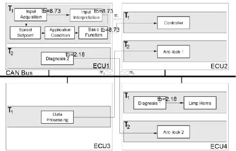
Les systèmes automobiles sont des systèmes distribués, embarqués et tems réel. Tout d'abord, les fonctionnalités logicielles des véhicules sont distribuées sur plusieurs composants matériels embarqués nommées unités de commande électronique (ang. ECU – Electronic Control Unit) ou sur des capteurs/actionneurs. La couche d'application qui s'étend sur des ECU différents est composée de composants logiciels qui peuvent être conçus et livrés par plusieurs fournisseurs. Le middleware est responsable de la communication entre les composants logiciels distribués. Chaque ECU exécute un système d'exploitation. Tout cela implique une nature distribuée des systèmes automobiles (voir la Figure 1). Deuxièmement leur fonctionnement est contraint par des contraintes de temps de différents types, par exemple des contraintes temporelles de bout-en-bout. Par exemple, l'ouverture de l'airbag en cas d'accident doit se produire dans les 20 ms. Cette dernière est une contrainte de temps réel, dont la violation non seulement affirme le comportement incorrect du système, mais plus important, peut mettre en danger la vie de personnes humaines.
x
Distributed Application
Middleware
OS OS OS
Network
Host 1 Host 2 Host n
Body Controller ECU
SWC1 SWC2 Input Acquisition Input Interpretation Speed Setpoint 30msSWC5 Diagnosis
Engine Management ECU
SWC6 SWC3 SWC4
Application
Condition FunctionBasic Controller Limp Home τ1 τ2 τ1 τ2 τ3 CAN Bus Distributed System Automotive System (Cruise Control System)
Figure 1. Système Distribué et Système Distribué Automobile
Les architectures de systèmes automobiles (en raccourci architectures automobiles) sont des produits très complexes, de haute technologie. Différents facteurs contribuent à leur complexité:
Taille: le nombre de fonctions contrôlées par le logiciel et le matériel est substantiel dans les véhicules d’aujourd’hui. En une trentaine d’années, la quantité de code est passée de 0 à près de 10 Go, ce qui représente des millions de lignes de code.
Nature distribuée: les architectures automobiles d’aujourd’hui sont fortement
distribuées, c.-à-d. les fonctions atomiques de la même fonctionnalités d’un véhicule sont distribuées sur plusieurs ECUs. Le même ECU peut accueillir des fonctions atomiques de différentes fonctionnalités du véhicule. Cela permet une meilleure optimisation de l'utilisation des ressources.
Les contraintes temps réel: le fonctionnement correct d'un système de véhicule
n'est pas seulement défini par l'absence d'erreurs fonctionnelles, mais aussi par strict respect des contraintes temps réel. Leur existence sert principalement dans les situations critiques pour la sécurité, comme le freinage ou pendant un accident lorsque les airbags doivent être activés immédiatement.
Exigences de sécurité: l’aspect de la sécurité joue un rôle important car
xi
Original Equipment Manufacturer) de fournir des véhicules fiables, mais aussi un sujet pour les réglementations gouvernementales.
Exigences contradictoires: les différentes exigences comme les contraintes de temps, la réduction des ressources matérielles pour réduire les coûts, la sécurité, etc. sont dans de nombreux cas des exigences orthogonales. Cela signifie que la satisfaction d'une exigence peut conduire la dégradation des autres exigences.
Sensible aux changements: de légers changements de conception ou certaines propriétés des éléments d'architecture peuvent conduire à une modification radicale des caractéristiques non-fonctionnelles d'architecture. Par exemple, l'augmentation d'un temps d'exécution d'une fonction atomique peut conduire à la violation de plusieurs contraintes de temps.
En raison de cette complexité qui a été et est encore en croissance exponentielle (prévue pour les 20 prochaines années), de nouvelles stratégies pour la conception des systèmes automobiles doivent être introduites. L'une d'entre elles est l'adoption de l'ingénierie dirigée par les modèles (IDM) pour le développement des systèmes automobiles. Le principe de l'approche IDM consiste à intégrer des modèles pour spécifier les exigences fonctionnelles et non fonctionnelles, et enfin, pour produire un code binaire qui respecte la spécification. Le potentiel de l’IDM a été identifié par les grands constructeurs automobiles et les fournisseurs qui ont initié un projet avec un objectif de fournir un standard commun fondé sur les principes de l’IDM. Ce projet appelé AUTOSAR (Automotive Open System Architecture) est actuellement le standard la plus influent en termes de modélisation des systèmes automobiles. La chaîne de développement de la méthodologie AUTOSAR (voir Figure 2) s'étend à partir de la représentation de composants logiciels d'application à l'infrastructure d'exécution, y compris la description de la plate-forme matérielle. Un inconvénient d’AUTOSAR est son manque de support pour la modélisation du niveau fonctionnel. Par conséquent, il y a un intérêt dans la combinaison de ce standard avec le langage de modélisation EAST-ADL2 qui prend en charge la spécification fonctionnelle.
xii
AUTOSAR Methodology
SWC1 SWC2 SWC3 SWC4
ECU1 ECU2 ECU3
ECU1 ECU2 ECU3
SWC1 SWC4 SWC3 SWC2 Vehicule Architecture Design System Configuration ECU1 SWC1 SWC4 RTE Extract ECU Specific Information RTE BSW ECU Configuration 0110101100011 0101111100110 0000011100110 1010101010100 1101010110100 ECU Executable Generation r1 SWC1 SWC4 SWC1 SWC4 r2 r6 r7 r1 r2 r6 r7
Figure 2. AUTOSAR Méthodologie
EAST-ADL2 et AUTOSAR imposent des règles méthodologiques pour la construction de modèles. Leur avantage est qu'ils fournissent un cadre commun pour la conception de systèmes électroniques automobile. Toutefois, aucune de ces méthodologies ne définit comment effectuer certaines étapes de conception, par exemple, la façon de distribuer les composants logiciels sur les éléments matériels ou comment partitionner des entités fonctionnelles sur des tâches OS (ang. Operating System). À cet égard, ces deux standards comptent entièrement sur une expérience de concepteur, augmentant ainsi le potentiel nombre de défauts de conception. En conséquence, il est essentiel de procéder à une analyse comme, l’analyse temporelle ou l'analyse de sécurité pour assurer que les décisions prises par le concepteur n'a pas conduit à des architectures irréalisables. Nous pouvons aller encore plus loin et utiliser des techniques pour l’exploration de l'espace de conception (ang. DSE – Design Space Exploration). Leur emploi pourrait assurer la faisabilité, mais en plus permet d'optimiser les propriétés non-fonctionnelles clés.
xiii
2. Énoncé du problème & motivation
Comme indiqué dans le paragraphe précédent, une vision claire et exhaustive d’une conception de système automobile, ainsi que son analyse / optimisation, sont les activités nécessaires pour rester compétitif sur le marché de l'automobile. Cela nécessite des langages de modélisation, de méthodes d'analyse et des techniques pour permettre le DSE. L'objectif général et initial de cette thèse est d'intégrer ces trois activités dans un cadre méthodologique, soutien de la conception des architectures automobiles et suivie par la méthodologie EAST-ADL2/AUTOSAR. Dans ce cadre, un ensemble de problèmes intéressants sont posés. La recherche de solutions appropriées est important pour rendre possible l'intégration de ces activités et la fourniture d'un flot continu guidé entre eux pour finalement produire un modèle d’implémentation optimisé d'un système automobile.
Disposer de différents types de modèles, c.-à-d. le modèle d'architecture, modèle d’analyse et modèle d'optimisation, est nécessaire pour effectuer une synthèse optimisée du logiciel avec le matériel. La phase principale de la synthèse est appelée déploiement. Selon AUTOSAR, le déploiement concerne 1) l’allocation des composants logiciels sur ECU 2) le partitionnement des entités du comportement du composant (appelées runnable entities) sur des OS tâches et enfin 3) l'ordonnancement des tâches OS. Un point crucial pour cette étape est sa validité en fonction de ses propriétés temporelles. Depuis le raffinement du système (dont le déploiement est une partie intégrante), la validité peut être assurée sous certaines hypothèses concernant des détails de niveau inférieur. Un exemple typique est l'hypothèse sur la connaissance des temps d'exécution pire cas (WCETs) des entités exécutables AUTOSAR. Il est évident que l'hypothèse de la connaissance précise des WCETs de runnables avant l’implémentation du code est la plupart du temps irréaliste. Dans de nombreux cas, certains runnables de systèmes précédents sont réutilisés. Le WCET de ces runnables est alors connu. Cependant, ce n'est pas le cas quand les nouveaux runnables implémentant de nouvelles fonctionnalités sont introduits. Cela représente un problème pour la synthèse de l'architecture et, en général, la fourniture d'un flot top-down. Ce qui est encore plus important est que le déploiement défini dans AUTOSAR n'est pas supporté de manière holistique par les techniques existantes. Bien que la quantité de travail qui existe semble être conséquente,
xiv
un fossé existe. Les techniques proposées soit représentent les tâches OS comme entités d’allocation ou résolvent le problème dans les étapes sans tenir compte d'un impact négatif qu'elle a sur les résultats finaux par rapport à l'approche holistique.
EAST-ADL2 et les spécifications AUTOSAR offrent un large éventail de concepts qui sont nécessaires pour définir l'architecture complète d’un système. Les efforts récents pour étendre ces standards ont fourni les capacités pour modéliser les informations nécessaires à l'analyse temporelle. Le travail adéquat n'a pas été fait jusqu'à présent pour gérer les optimisations. Bien que le domaine temps réel et des systèmes distribués est riche en techniques d'optimisation, il n'y a pas de concepts de modélisation qui permettraient de spécifier une entrée nécessaire pour cette activité tels que les objectifs d'optimisation (temps des réponses, la consommation de mémoire, etc.). En conséquence, la modélisation et l'analyse/l'optimisation ne sont pas bien intégrées. Cela a abouti à de nombreux outils décousus pour la modélisation ou l'analyse et/ou l'optimisation.
3. Contributions
Afin de permettre de développement sans couture dans le cadre proposé, ce travail propose un ensemble de solutions aux problèmes mentionnés ci-dessus:
1) Concernant les techniques de DES les principales contributions portent sur la
définition de nouvelles techniques pour optimiser le déploiement. Les techniques proposées sont conformes à la définition du déploiement comme inclus dans le standard AUTOSAR. C'est-à-dire, ils considèrent les runnable entities que les unités d’allocation. Par conséquent, l'étape de partitionnement qui n'est pas considérée par les approches existantes est supportée par la technique définie dans ce travail. Les techniques proposées sont basées sur des heuristiques, algorithmes évolutionnistes, diviser pour régner, amélioration itérative, c'est pourquoi ils sont capables de traiter de grandes architectures d'entrée. Cette caractéristique a été évaluée en effectuant plusieurs tests, atteignant 250 runnables. Un critère d'évaluation important a été la qualité des architectures déployées. Ceci a été réalisé en comparant les résultats à ceux obtenus avec les méthodes exactes ou des architectures pour lesquelles la configuration optimale de déploiement était connue a priori. Dans AUTOSAR, des modèles de comportement
xv
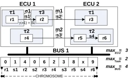
pourraient correspondre soit à une sémantique d'exécution data driven ou time driven. Cela nécessite de définir les différents types de stratégies d'optimisation. La différence se situe dans l’analyse d'ordonnançabilité. En outre, les métriques d'optimisation telles que les métriques temporelles, les métriques de mémoire sont affectées d’une manière différente par les choix particuliers d'un déploiement. Ce qui caractérise aussi les techniques proposées est la prise en compte de critères multiples (par exemple, les réponses de bout-en-bout, les propriétés temporelles, la consommation mémoire) qui définit une bonne configuration de déploiement de l'architecture d'entrée. La Figure 3 montre un exemple de l'architecture logicielle d'entrée (partie supérieure) et sa spécification de déploiement.
Figure 3. Exemple de l'architecture logicielle d'entrée (partie supérieure) et sa spécification de déploiement (partie basse)
.
2) Pour améliorer les résultats d'un déploiement, ce travail suggère un raffinement de
la méthodologie EST-ADL2/AUTOSAR. Le but est de permettre de résoudre de manière holistique le problème de déploiement, ce qui n’est pas possible avec définition
xvi
actuelle de cette méthodologie. Le changement concerne la répartition des responsabilités entre les deux niveaux, le niveau fonctionnel couvert par EST-ADL2 et le niveau implémentation couvert par AUTOSAR. L'activité Design qui se fait au niveau fonctionnel comprend l'étape d’allocation des fonctions atomiques aux ressources matérielles, c.-à-d. ECUs. Ceci détermine la répartition des runnable entities en raison de l'hypothèse dans laquelle les runnable entities sont transformés à partir des fonctions atomiques. C'est pourquoi le problème de déploiement ne peut pas être résolu d’une manière holistique au niveau AUTOSAR parce qu’une dimension du problème, c.-à-d. l'allocation est déjà fixée. Par conséquent, ce travail préconise le changement dans lequel l'allocation est reportée jusqu'au niveau d’implémentation. L’évaluation de ce changement montré une amélioration remarquable des caractéristiques de l’architecture.
3) Pour effectuer un déploiement qui optimise les réponses de bout-en-bout, les
temps d'exécution des runnable entities sont nécessaires. Comme cette information peut-être manquante pour certains runnables, la définition d'une nouvelle stratégie pour la configuration de l'architecture est inévitable. Pour contourner le problème, certains travaux proposent d'ajouter à la méthodologie d'une activité appelée budgétisation de temps (ang. time budgeting). Au lieu d'estimer WCETs, l'intégrateur de système spécifie des budgets temporels (ang. time budgets), c'est à dire des contraintes à des temps de réponse pire cas - WCRTs (ang. Worst Case Execution Times). Les budgets temporels doivent être respectés par les fournisseurs livrant l’implémentation des composants. Le problème typique de cette approche est que le fournisseur livre l’implémentation d'un composant particulier, qui sera intégrée par l'intégrateur en tant que partie intégrante du système, dans une étape ultérieure. Entre temps, le fournisseur valide le composant en isolation, sans tenir compte d'éventuelles interférences avec d'autres composants. Il est alors incapable de calculer un temps de réponse pire cas (WCRT) correct. C'est-à-dire si le composant répond à la contrainte du budget temporel l'intégrateur du système doit prendre soin d'éviter toute interférence possible avec d'autres composants. Ce n'est pas seulement une tâche difficile, mais qui provoque généralement un surdimensionnement des ressources. Ce surdimensionnement des ressources peut représenter des coûts insoutenables pour une production en série. Une solution alternative est celle dans laquelle les budgets temporels représentent des contraintes de WCET de runnable entity
xvii
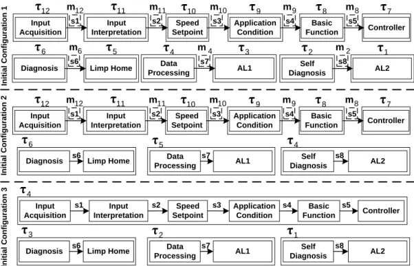
à la place de son WCRT. Ce travail propose une solution de budgétisation des WCETs. La plupart des travaux existants sur budget de WCRT ne pas bien adaptés à l'idée de « l'architecture intégré » proposée par AUTOSAR. Un autre avantage de la technique proposée dans ce travail par rapport aux approches existantes est l'hypothèse que le déploiement n'est pas connu à l'avance. En conséquence, un objectif de la technique proposée est de trouver conjointement le déploiement et l'affectation optimale des budgets temporels. La Figure 4 illustre une architecture logicielle d'entrée et une architecture matérielle pour lesquelles le déploiement ainsi que les budgets de temporels doit être spécifié. En fait, les budgets temporels doivent être définis pour ces runnable entities pour lesquels les informations sur le WCET n'est pas présent. La Figure 5 présente le résultat de la technique proposée, c.-à-d. l'architecture déployée ainsi que les budgets temporels.
xviii
Figure 5. Résultant Déploiement avec la Spécification des Budgets Temps
4) En ce qui concerne la modélisation de la première contribution, une spécification de concepts essentiels pour construire un modèle d'optimisation et pour exécuter des techniques DES telles que celles définies dans ce travail, servant pour le déploiement ou budgétisation de temps, a été réalisée. La Figure 6 représente une partie du profil UML définissant les principaux concepts permettant de construire un contexte d'optimisation. Au-dessus du modèle d'optimisation, des techniques d'optimisation peuvent être exécutés.
xix
Figure 6. UML Profile pour le contexte d'optimisation
5) Les modèles d'optimisation ainsi que des modèles pour l'analyse et la
spécification de l'architecture sont basés sur UML. L'utilisation de l'UML permet de faciliter l'intégration des différentes activités. Ceci est obtenu en majeure partie par l'ensemble des transformations qui automatisent des étapes importantes telles que la production du modèle AUTOSAR préliminaire à partir du modèle EAST-ADL2. En fait, la spécification d'architecture basée sur les concepts de EAST-ADL2 et AUTOSAR est réalisée dans ce travail par un mécanisme de profil UML. Le profil UML complet pour l'EST-ADL2 était disponible. Ce n'était pas le cas pour AUTOSAR et donc ce travail en définit un. Les modèles d'analyse sont établis avec SysML et MARTE pour lesquels les profils UML ont été définis et standardisés par l'OMG (Object Management Group). Les concepts pour l'optimisation ne peuvent pas être exprimés ni avec SysML, ni MARTE ainsi qu’EST-ADL2 et AUTOSAR. En conséquence, pour eux, un modèle de domaine est formalisé et son profil UML est défini comme susmentionné dans le cadre de la contribution 4.
Tous ces modèles, modèles d'architecture, d'analyse et d'optimisation avec des algorithmes d’analyse et d'optimisation peuvent être exécutés et ont été intégrés dans un cadre et structurés le long de couches d'abstraction et de points de vue. Le cadre lui-même (appelé AFfMAO – Architecture Framework for Modeling Analysis and Optimization) a été développé comme une instance d'un Cadre d'Architecture de
xx
l'Automobile (ang. Automotive Architecture Framework - AAF) définie dans ce travail. AAF a été construit en suivant les principes du Cadre Architectural (ang. Architecture Framework - AF) définie dans la norme ISO 42010. Cette relation est représentée sur la partie gauche de la Figure 7. En substance, le cadre d'architecture est un ensemble de conventions, principes et pratiques pour la description des architectures dans un domaine et/ou communauté des parties prenantes. Par conséquent la spécification de l'AAF a été faite en définissant des points de vue de l'architecture avec leurs préoccupations, sortes de modèles et de règles de correspondance. Le côté droit de la Figure 7 présente la perspective détaillée de AFfMAO. Les informations pertinentes à partir de cette figure concernent les choix des techniques de modélisation, un ensemble de transformations, des algorithmes d'analyse et d'optimisation et plate-forme utilisée pour réaliser l'AAF comme AFfMAO.
Figure 7. AFfMAO construit comme une instance de l'AAF
Les contributions de cette thèse apportent des solutions pour résoudre les problèmes cruciaux qui entravent la livraison d'un cadre pour une conception guidée des systèmes automobiles, alignés sur les principes de l'ingénierie dirigée par les modèles. Ils sont bénéfiques non seulement dans le contexte de ce cadre particulier, mais en général à ces constructeurs qui tentent de s’engager dans l’utilisation des standards EAST-ADL2 et AUTOSAR comme base de conception de leurs systèmes.
ARGateway EAXmlGen EAQomp Gateway ARQomp Gateway ARXmlGen <eaxml> <arxml> Analysis and Optimization UML Pr ofile for EAS T-ADL2 UML Pr ofile for A UT OS AR Architecture Framework (ISO 42010)
Automotive Architecture Framework - AAF
Automotive Framework for Modeling Analysis and Optimization (AFfMAO)
Vi ewpoi n ts Cor res ponde n ce Rul es Concerns Mo del Ki nds St ak eh ol de rs Qompass Framework MARTE + SysML
xxii
TABLE OF CONTENTS
1. Introduction --- 30
1.1. Context --- 30 1.2. Problem Statement & Motivation --- 33 1.3. Contribution outlines --- 35 1.4. Thesis Structure --- 37
2. Automotive Context --- 39
2.1. Automotive System --- 39 2.2. Model Driven Engineering --- 45 2.3. Architecture Framework --- 46 2.4. Automotive Standards --- 47 2.4.1. AUTOSAR --- 47 2.4.2. EAST-ADL2 --- 49 2.5. Methodology of Design (EAST-ADL2/AUTOSAR Methodology) --- 50
3. Challenges --- 56
3.1. General Challenges --- 56 3.2. Configuration of Automotive Architectures --- 58 3.3. Architecture Description Specification --- 60 3.4. Conclusions --- 61
4. Approaches for the Computer-aided Configuration of the Automotive
Architectures --- 62
4.1. Formalism --- 62 4.1.1. Data Driven Activation --- 65 4.1.2. Time Driven Activation --- 66 4.2. Schedulability Analysis --- 68
xxiii
4.2.1. Schedulability Analysis for DD --- 68 4.2.2. Schedulability Analysis for TD --- 70 4.3. Refinement of the EAST-ADL2/AUTOSAR Methodology --- 72 4.4. Deployment --- 73 4.4.1. Formalization of Deployment --- 73 4.4.2. Related Work --- 80 4.4.3. Technique for Optimized Deployment of DD --- 83 4.4.4. Evaluation & Conclusions --- 88 4.4.5. Technique for Optimized Deployment of TD --- 95 4.4.6. Evaluation & Conclusions --- 97 4.5. Two-Step Approach --- 104
4.5.1. GA Formulation for the Two-Step Approach --- 105 4.5.2. Establishment of the Global Order --- 108 4.5.3. Evaluation & Conclusions --- 110 4.6. Evaluation of the new Methodology --- 115
4.6.1. Allocation at the EAST-ADL2 Level --- 116 4.6.2. Partitioning and Scheduling at the AUTOSAR level --- 117 4.6.3. Evaluation & Conclusions --- 117 4.7. Time Budgets Assignment --- 119
4.7.1. Formalism --- 120 4.7.2. Related Work --- 121 4.7.3. Method for Time Budgeting --- 123 4.7.4. Evaluation & Conclusions --- 131 4.8. Conclusions --- 139
5. UML based & Optimization-aware modeling of the Automotive
Architectures --- 140
5.1. Related Work --- 141 5.1.1. Commercial Tooling --- 141 5.1.2. Academia Tooling --- 143 5.1.3. Automotive Architecture Framework --- 143 5.1.4. Related Work Conclusions --- 146
xxiv
5.2. Automotive Framework for Modeling Analysis and Optimization --- 147 5.3. Viewpoints --- 149 5.3.1. Feature, Functional and Design Level Viewpoints --- 152 5.3.2. Technical Level Viewpoints --- 160 5.3.3. Generation Viewpoint --- 169 5.3.4. Analysis Viewpoint --- 172 5.3.5. Optimization Viewpoint --- 177 5.4. Interoperability Viewpoints --- 183 5.5. Correspondence Rules --- 184 5.5.1. EAST-ADL2 and AUTOSAR --- 184 5.5.2. EAST-ADL2 and Analyzable Model --- 185 5.5.3. AUTOSAR and Analyzable Model --- 186 5.6. Conclusions --- 187 6. Conclusion --- 188 6.1. Summary --- 188 6.2. Future Work --- 190 References --- 192 Appendix --- 201 A. Tool Prototype --- 201 B. AAF Revisited--- 208
xxv
LIST OF FIGURES
Figure 1. Système Distribué et Système Distribué Automobile ... x Figure 2. AUTOSAR Méthodologie ... xii Figure 3. Exemple de l'architecture logicielle d'entrée (partie supérieure) et sa
spécification de déploiement (partie basse) ... xv Figure 4. L’architecture Logicielle et Matérielle avec certains Runnables qui manquent
WCETs ... xvii Figure 5. Résultant Déploiement avec la Spécification des Budgets Temps ... xviii Figure 6. UML Profile pour le contexte d'optimisation ... xix Figure 7. AFfMAO construit comme une instance de l'AAF ... xx Figure 1.1. Distributed System and Automotive Distributed System ... 31 Figure 2.1. Conceptual Model of Architecture Description and Architecture Framework.
... 47 Figure 2.2. AUTOSAR Architecture Layers Schema ... 49 Figure 2.3. EAST-ADL2 Abstraction Layers ... 50 Figure 2.4. AUTOSAR Methodology ... 53 Figure 2.5. EAST-ADL2/AUTOSAR Methodology ... 55 Figure 4.1. Data Driven Activation Model ... 66 Figure 4.2. Time Driven Activation Model ... 68 Figure 4.3. Example of a Chromosome for a Specific Deployment Configuration .... 85 Figure 4.4. OX3 Crossover Operator ... 87 Figure 4.5. Simple Use-Cases ... 90 Figure 4.6. Solutions for the Simple Use-Cases obtained with the Metric 4.13 ... 91 Figure 4.7. Solution for the Simple Use-Case nr 4 obtained with the Metric 4.12 ... 91 Figure 4.8. CCS + ABS System ... 92 Figure 4.9. Non-replicated Use-Case ... 93 Figure 4.10. Comparison of the Optimal Solution with the Solution obtained with the
GA. ... 94 Figure 4.11. Runtimes for the GA with Different Initial Population ... 95
xxvi
Figure 4.12. Example of a Chromosome for a Specific Deployment Configuration in the Context of the TD ... 97 Figure 4.13. Non-replicated Use-Case with TD Semantics ... 99 Figure 4.14. Optimal Configurations for Non-replicated Use-Case ... 99 Figure 4.15. Results for MILP and GA ( ... 100 Figure 4.16. Results for MILP and GA ( ... 100 Figure 4.17. Runtime for MILP and GA ( ... 101 Figure 4.18. Runtime for MILP and GA ( ... 102 Figure 4.19. Comparison using Fitness Function ( ) ... 103 Figure 4.20. Comparison using Fitness Function ( ) . 103 Figure 4.21. The Two-Steps Deployment Approach (TSDA) ... 105 Figure 4.22. Example of a Chromosome for a particular Allocation Configuration 106 Figure 4.23. Example chromosome for the Partitioning and Scheduling Configuration
... 108 Figure 4.24. Example of the Input Configuration ... 109 Figure 4.25. Global Order for the Example of the Figure 4.24 ... 109 Figure 4.26. Initial Configuration for the Simple Use-Case ... 111 Figure 4.27. Comparison of the Two Steps Approach with the Holistic Approach and the
Optimal Solution ... 112 Figure 4.28. Runtimes of the OS-GA and the TSDA-GA ... 113 Figure 4.29. Initial Configurations for the ABS + CCS ... 114 Figure 4.30. Comparison between the results of the MCDT and the Holistic Approach
... 118 Figure 4.31. Iterative Improvement Loop for the Staged Approach ... 129 Figure 4.32. Deployment Configuration for CCS and ABS ... 132 Figure 4.33. Results for One-step and Staged Approach (GA Initial Population = 10000)
... 134 Figure 4.34. Runtimes of One-step and Staged TTBA (GA initial population = 10000)
... 135 Figure 4.35. Comparison of two different metrics for Staged TTBA ... 136
xxvii
Figure 4.36. Comparison of Number of Iterations of two different metrics for Staged TTBA ... 137 Figure 5.1. AFfMAO built as an instance of the AAF ... 148 Figure 5.2. Layers and Viewpoints of the Automotive Architecture Framework .... 150 Figure 5.3. Levels of the EAST-ADL2 Model ... 151 Figure 5.4. Part of the EAST-ADL2 Metamodel for the FAA from [6] ... 153 Figure 5.5. Model of two Features ... 153 Figure 5.6. Part of the EAST-ADL2 Metamodel for the FunAA and FDA from [6] 154 Figure 5.7. Function Types at the Function Layer ... 154 Figure 5.8. Function Prototypes at the Function Layer ... 155 Figure 5.9. Function Types at the Design Layer ... 156 Figure 5.10. Function Prototypes at the Design Layer ... 156 Figure 5.11. Hardware Architecture Modeling in the EAST-ADL2 ... 157 Figure 5.12. Model of the Hardware Types ... 157 Figure 5.13. Model of Hardware Prototypes ... 158 Figure 5.14. Model of the Allocation ... 158 Figure 5.15. Model with Timing Information ... 160 Figure 5.16. Model of Software Component Types ... 161 Figure 5.17. Model of Software Component Prototypes ... 162 Figure 5.18. Model of Hardware Types based on the AUTOSAR Standard ... 163 Figure 5.19. Model of Hardware Prototypes based on the AUTOSAR Standard ... 163 Figure 5.20. Model of the Internal Behavior for the CruiseControlInput Software
Component ... 164 Figure 5.21. Metamodel used for the ECU Configuration [97] ... 165 Figure 5.22. Partitioning of the Runnable InputAcquisition in the task t1 ... 167 Figure 5.23. Specification of a Latency Constraint for the End-to-End flow under the
Application Timing Viewpoint (at the AUTOSAR SystemTiming Level) ... 169 Figure 5.24. Specification of the Activation Period under the Application Timing
Viewpoint (at the AUTOSAR SystemTiming Level) ... 169 Figure 5.25. UML Profile used to specify the Generation Strategy within the Generation
xxviii
Figure 5.26. Generation Model providing a strategy for the generation of the Runnable Entities and the Software Components ... 172 Figure 5.27. Analyzable Model representing System Behavior under the Analysis
Viewpoint ... 175 Figure 5.28. Model of Hardware Types specified within the Analysis Viewpoint ... 176 Figure 5.29. Model of Hardware Prototypes specified within the Analysis Viewpoint176 Figure 5.30. Model of a Complete Analysis Context containing specification of the
Allocation, Partitioning and Scheduling. ... 177 Figure 5.31. UML Profile for the Optimization Context ... 179 Figure 5.32. UML Profile for the Exploration Parameters ... 180 Figure 5.33. UML Profile for the Optimization Objective ... 181 Figure 5.34. UML Profile for the Optimization Technique based on the Genetic
Algorithms ... 182 Figure 5.35. Optimization Model created under the Optimization Viewpoint ... 183
LIST OF TABLES
Table 4.1. Basic Architecture Elements ... 65 Table 4.2. Additional Concepts for the Data Driven Activation Model ... 65 Table 4.3. Additional Concepts for the Time Driven Activation Model ... 67 Table 4.4. Additional Notation for TD ... 79 Table 4.5. Summary of the Related Work for DD ... 82 Table 4.6. Summary of the Related Work for TD ... 83 Table 4.7. Intermediate Results for each Initial Configuration ... 115 Table 4.8. Additional Formalism for Time Budgeting ... 121 Table 4.9. Summary of the Related Work for Time Budgeting ... 123 Table 4.10. Results for Time Budgets Assignments and Initial Constraints ... 132 Table 4.11. Properties of the Testing Input Architectures ... 133 Table 4.12 Runtimes (seconds) of one-step and staged approach (GA initial population =
10000) when using different budgeting algorithms ... 138 Table 5.1. Features of the Frameworks/Tools for the Automotive Domain ... 147
xxix
Table 5.2. UML Profile for the AUTOSAR metamodel used by the Application Viewpoint ... 161 Table 5.3. UML Profile for the AUTOSAR metamodel used by the Topology Viewpoint
... 162 Table 5.4. UML Profile for the AUTOSAR metamodel used by the Internal Behavior
Viewpoint ... 164 Table 5.5. UML Profile for the AUTOSAR metamodel used by the Allocation
Viewpoint ... 164 Table 5.6. UML Profile for the AUTOSAR metamodel used by the ECU Configuration
Viewpoint ... 167 Table 5.7. UML Profile for the AUTOSAR Timing Extension Metamodel used by the
Application Timing Viewpoint ... 168 Table 5.8. Metamodel for the specification of Generation Strategy ... 171 Table 5.9. MARTE subset used for the Analysis Context and its SysML Extensions174 Table 5.10. Correspondence Rules between the Design and Technical Level Viewpoints
... 185 Table 5.11. Correspondence Rules between the EAST-ADL2 Model and the Analyzable
Context ... 186 Table 5.12. Correspondence Rules between the AUTOSAR Model and the Analyzable
Context ... 187 Table B.0.1. Viewpoints of the AAF with their Concerns and Model Kinds ... 210
30
1.
Introduction
This introductory chapter gives an overview over the problems defining the scope of this work and lists the main contributions which aroused to handle them. For seek of clarity, it starts with a brief presentation of the context to which the thesis’ problems relate. The context description will be broadened in the next chapter to provide to the reader an exhaustive synthesis of all the concepts fundamental to clear understanding of this work.
1.1. Context
Nowadays vehicle systems are marked by a wide range of software-based solutions that improve performance, safety and comfort of driving. Features like the self-parking system were beyond belief for ordinary drivers just 10 years ago. Not mentioning that we cannot still frame in our mind the vehicles driving autonomously, which is currently happening as few running examples were already prototyped.
From now on the term automotive/vehicle system will relate to those functionalities of a vehicle which are delivered through a combination of both software and hardware solutions. Automotive systems are perceived as distributed, embedded, real-time systems. First, software-based vehicle features are distributed on several embedded hardware components named Electronic Control Units (ECU) or on sensors/actuators. The application layer that spans over different ECUs is composed of the software components that can be delivered by multiple suppliers. The middleware is responsible for the communication between distributed software components. Each ECU runs an Operating System. All of this implies a distributed nature of the automotive systems (see Figure 1.1). Secondly their operation is tightened by the timing constraints of different kinds, e.g. the end-to-end response timing constraints. For instance the opening of the airbags during an accident should occur within 20ms. The last is a real-time constraint whose violation not only states the incorrect behavior of the system, but more importantly, can endanger a human’s life.
31
Distributed Application
Middleware
OS OS OS
Network Host 1 Host 2 Host n
Body Controller ECU
SWC1 SWC2 Input Acquisition Input Interpretation Speed Setpoint 30msSWC5 Diagnosis
Engine Management ECU
SWC6 SWC3 SWC4 Application
Condition FunctionBasic
Controller Limp Home τ1 τ2 τ1 τ2 τ3 CAN Bus Distributed System Automotive System (Cruise Control System)
Figure 1.1. Distributed System and Automotive Distributed System
Automotive systems architectures (in short automotive architectures) are very complex high technology products. Architecture itself is defined as in the following Definition 1.1.
Definition 1.1 – Architecture: fundamental concepts or properties of a system in its
environment embodied in its elements, relationships, and in the principles of its design and evolution [1].
Different factors contribute then to the complexity of automotive system architecture:
Size: the number of features controlled by the software and hardware is substantial in nowadays premium cars. Within around 30 years the capacity of a code has increased from 0 to almost 10GB which implies millions of lines of code.
Distributed nature: the first software-based solutions were very local and isolated. This was achieved by having only one feature per ECU. However the growing number of the SW features forced the automotive industry to shift towards distributed architectures. The “one feature one ECU” approach became very costly due to the increasing demand for the hardware elements. The additional motivation for that it was the shrinking physical space in the car which prevents further expansion of a hardware plant. As a result, nowadays automotive architectures are highly distributed, i.e. functions of the same feature span over different ECUs. The same ECU might host
32
functions of different features. This lead to a better optimization of the resources usage. Nonetheless it imposes a big challenge when designing such distributed architectures.
Real-time constraints: correct functioning of a vehicle system is not only defined through the absence of functional errors but also by the means of a strict observance of the hard real-time constraints. Their existence serves primarily in a safety critical situations, like braking or during an accident when the airbags should be activated immediately. However in the competitive automotive world OEMs put high timing demands also on the features which don’t have any impact on the safety aspect, e.g. features classified as the infotainment.
Safety requirements: the safety aspect plays an important role as nowadays it is not only an internal concern of an OEM to provide reliable vehicles, but also a subject for regulations provided by the ISO [2].
Conflicting requirements: all the different requirements like timing constraints, reduction of the hardware resources to lower the costs, provision of safety, etc. are in many cases orthogonal. This means that the satisfactory handling of one requirement can lead to the violation or deterioration of the others.
Sensitive to changes: slight changes of a design or certain properties of particular architecture artifacts can lead to a radical modification of the architecture non-functional characteristics. For example, increase of an execution time of a single functional entity might lead to the violation of few timing constraints.
Due to this complexity that was and is still growing exponentially (as presumed to be for the next 20 years [3]), new strategies for design of the automotive systems need to be introduced. As a response, a number of initiatives have emerged, which either directly relates to the automotive systems or indirectly as they concern in general the distributed real-time architectures. Among them is the adoption of the model driven engineering (MDE) for the development of the automotive electronic systems [4]. The principle of the MDE approach is to incorporate abstract, in many cases graphical models to specify the functional and non-functional requirements, and finally, to produce a binary code that will fully respect the specification. The potential of the MDE has been spotted by the major car manufacturers and suppliers which initiated a project with a goal to provide a common standard drawing on the principles of the MDE. It is called
33
AUTOSAR (AUTomotive Open System ARchitecture) [5] and currently, this standard is the most influential in terms of modeling automotive systems. The development chain of the AUTOSAR methodology stretches from the depiction of application software components to the runtime infrastructure, including the description of the hardware platform. A related drawback of the AUTOSAR is its lack of support for the function-level modeling. Therefore there is a growing interest in combining this standard with the EAST-ADL2 [6] modeling language which targets the abstract, functional specification.
Besides the language aspect, the EAST-ADL2 and the AUTOSAR impose methodological rules for building the models. Their advantage is that they provide a common framework for the design of automotive electronic systems. However neither of those define how to perform certain design steps, e.g. how to distribute software components across hardware elements or how to map functional entities into OS (Operating System) tasks. In that respect, these two standards completely rely on a designer experience, increasing thereby the number of potential design flaws. As a consequence it is essential to conduct analysis like, timing or safety analysis to assure that the decisions made by the designer didn’t lead to unfeasible architectures. We can go even beyond that and use techniques for Design Space Exploration (DSE) [7]. Their employment might not only assure the feasibility but in addition can optimize the key non-functional properties. This might lower the system final cost or increase the reusability of the architecture constituents.
1.2. Problem Statement & Motivation
As outlined in the previous subsection, clear and comprehensive view on an automotive system design, as well as its analysis/optimization, are crucial activities on a way to develop high-quality architectures. This requires appropriate modeling languages, analysis methods and techniques for enabling DSE. The general and initial objective of this thesis is to integrate these three activities within one complete methodological framework, supporting the design of the automotive architectures, followed by the EAST-ADL2/AUTOSAR methodology. Within this context, a set of problems aroused. As shown later, finding of appropriate solutions is significant to make possible the final integration of the above activities and provision of the guided seamless flow between them, to finally deliver optimized implementation model of an automotive system.
Having different types of models, i.e. architecture model, analyzable model and optimization model, is the main step towards the ability to perform an optimized synthesis of the software with
34
the hardware. The main phase of the synthesis is called deployment (see Definition 1.3). According to AUTOSAR, the deployment concerns the 1) allocation of the software components into the ECUs, 2) partitioning of the component’s behavioral entities (so called runnable entities) in the OS tasks, and finally 3) scheduling of the OS tasks. The deployment step is done at the abstract modeling level which speeds up the design process as it is not delayed by awaiting the final code implementation. A crucial point for this step is about its validity in terms of its timing properties. Since the system refinement (of which deployment is an integral part) is done top-down, validity can be assured only under some assumptions abstracting lower-level details. A typical example is the assumption about the knowledge of the worst-case execution times (WCETs) of the AUTOSAR runnable entities. It is obvious that the assumption about the
precise knowledge of runnables’ WCET before code implementation is most of the time unrealistic. In many cases, implementation of certain runnables is re-used from previous
systems, hence their WCET is known. However it is not true when new runnables are introduced.
This causes the problem in the attempt to deliver guided strategies for the architecture synthesis and in general, provision of an undisrupted top-down flow within the framework. What is even more significant is that the deployment itself in a way as it is defined by the AUTOSAR is not holistically supported by the existing techniques. Although the amount of
work that exists seems to be compelling and representative, there is a gap. Proposed techniques
either account for the OS tasks as the allocable entities or solve the problem in stages without consideration of a negative impact it has on a final results when compared to the holistic approach.
Definition 1.2 – Synthesis: derivation of a system from its specification.
Definition 1.3 – Deployment: synthesis step to determine the allocation of functional entities,
their partitioning in OS tasks and assignment of priorities for the tasks.
The EAST-ADL2 and the AUTOSAR specifications deliver a broad range of concepts that are necessary to define the complete system architecture. Recent efforts in a further extension of these standards provided even the capabilities to model the information needed for the timing analysis [8]. This triggered some work showing specific kinds of timing analysis (e.g. schedulability analysis) that can be run and how the timing model should be interpreted to do this [9]. The adequate work hasn’t been done so far to handle the optimizations. Though the field of
35
real-time and distributed systems abounds in optimization techniques, there are no modeling concepts that would enable specifying an input necessary for this activity such as the optimization objectives (timing responses, memory consumption, etc.) or their priority, which plays an important role when optimizing orthogonal concerns. As a consequence the
modeling and the analysis/optimization are not well integrated, namely consideration of these two problems simultaneously is not the case. This has resulted in many tools that deal either with the modeling or the analysis and/or optimization. As a consequence, it is difficult to embed these tools in the standard methodologies such as the EAST-ADL2/AUTOSAR methodology. This especially applies to the higher abstraction layers as those defined by the EAST-ADL2. It is a consequence of a high dependability of analysis/optimization tool on the platform specific information.
1.3. Contribution outlines
In order to enable the seamless development flow within the proposed framework this work offers a set of solutions to the aforementioned problems:
1) From the Design Space Exploration (DSE) techniques side, the main contributions relate to
the definition of new techniques for optimizing the deployments. The proposed techniques are compliant with a way in which the deployment is defined by the AUTOSAR standard. That is to say, they consider the runnable entities as allocable units. Therefore the partitioning step is supported which is out of the scope of what current approaches are offering. Proposed techniques are based on evolutionary algorithms which is why they are able to handle large input architectures. This ability was evaluated by performing multiple tests, reaching 250 runnables. Accompanying significant aspect that is assessed this is the quality of the delivered, deployed architectures. This was done by comparing the results to those acquired with the exact methods or to the architectures for which the optimal deployment configuration was a priori known. Within the AUTOSAR, behavioral models might conform either to a data driven or time driven execution semantics, requiring hence to define different types of optimization strategies. The difference occurs on behalf of the timing analysis which diverse. Furthermore optimization metrics such as the timing or the memory are affected in an unlike way by the particular choices of a deployment. What also characterizes proposed techniques is the consideration of the multiple criteria (e.g. end-to-end timing responses, memory consumption) that defines a sound deployment configuration of the input architecture.
36
2) To improve the results of a deployment, this work suggests a refinement of the
methodology uniting the EAST-ADL2 and the AUTOSAR methodologies. The purpose of doing so is to enable holistic consideration of the deployment problem, which as will be shown cannot be done with the current definition of this combined methodology. The impact of the changes is evaluated and shows significant improvement in regards to the metrics considered all along the deployment process.
3) In order to enable a qualitative deployment in regards to the optimization metrics, certain
information is required. For instance to perform a deployment that optimizes the end-to-end response times, execution times of the runnable entities are necessary. As this information might be missing for certain runnables, definition of a new strategy for the architecture configuration is unavoidable. As a workaround, certain works propose to add to the methodology a special activity called time-budgeting. Instead of estimating worst-case execution times, the system integrator specifies so-called time budgets, i.e. constraints to the worst-case response times. Time budgets must be respected by the suppliers delivering the component implementation. The typical problem with this approach is that a supplier delivers the implementation of a particular component, which will be integrated as an interacting part of the system by the system integrator, in a later stage. Since the supplier will validate the component in isolation, without taking into account possible interferences of other components, it will be incapable of computing a correct worst-case response time (WCRT). In a sense if the component fulfills the time-budget constraint, the system integrator should take care of avoiding any possible interference with other components, which is not only a difficult task, but that typically inflates resource over-dimensioning. Such resource over-dimensioning turns into unsustainable costs for a mass-production. An alternative solution is the one in which time-budgets represent constraints to runnable’s execution time, i.e. worst-case execution time (WCET) instead of WCRTs. The main question that remains now is how to specify this constraint. This thesis provides a solution, compliant with the AUTOSAR methodology and the one that will automatically assign the values for time budgets.
4) From the modeling side the first contribution is a specification of concepts essential to
build an optimization model and to run Design Space Exploration techniques.
5) Optimization models as well as models for the analysis and architecture specification are
37
This is attained for the most part by the set of transformations automating significant steps such as the generation of the preliminary AUTOSAR model out of the EAST-ADL2 model. In fact the architecture specification is achieved basing on the concepts of the EAST-ADL2 and the AUTOSAR and to model them this work uses a UML profile mechanism. The complete UML profile for the EAST-ADL2 already exists which is not the case for the AUTOSAR and hence this work defines one. The analysis models are established with the SysML [11] & MARTE [12] for which the UML profiles were defined and standardized within the OMG (Object Management Group). The concepts for the optimization cannot be expressed neither with the SysML nor MARTE as well as the EAST-ADL2 and the AUTOSAR. Consequently for them, a separate domain model is formalized and its related UML profile is defined.
Established contributions solve the crucial problems hindering the delivery of a framework for a guided design of the automotive systems aligned to the principles of the Model Driven Engineering. They are beneficial not just within the context of this particular framework, but in general to those OEMs who tries to engage the EAST-ADL2 and the AUTOSAR standards as the baselines for their systems.
1.4. Thesis Structure
Chapter 2 - Automotive Context: gives a general overview over the current trends in the
automotive domain. It presents the main standards and the methodology for designing automotive architectures. The intent of this chapter is to provide detailed picture of the context and the fundamentals related to this thesis.
Chapter 3 – Challenges: lists and describes the main challenges identified for the automotive
domain.
Chapter 4 – Approaches for the Computer-aided Configuration of the Automotive Architectures: relates to the contributions 1, 2 and 3 described in the section 1.3. It demonstrates
a set of techniques contributing to the existing strategies used for the deployment of the real-time distributed architectures. It also presents strategies for the time budgeting and the refinement of the EAST-ADL2/AUTOSAR methodology. All this is evaluated to show the added value of the new techniques and the refined methodology.
Chapter 5 – UML based & Optimization-aware modeling of the Automotive Architectures:
presents the contribution related to the UML modeling of the automotive architectures (contributions 4 and 5 described in the section 1.3). Above all it is the specification of the UML
38
profile that serves to express the optimization concerns. Accompanying is the presentation of the UML profile for the AUTOSAR and a set of transformations between different models (architecture model, analysis model and optimization model) that empower the overall integration of different activities within the framework.
Chapter 6 – Conclusion: concludes this dissertation and draws possible directions for the future
39
2.
Automotive Context
This chapter starts by introducing the context of this thesis, i.e. automotive systems. Then it demonstrates the nowadays trends in the automotive domain by first discussing the employment of the Model Driven Engineering and then presenting the concept of an Architecture Framework The last establishes terminology based on which framework discussed within this work was built. Following is the overview of the most current and significant standards, i.e. the AUTOSAR [5] and EAST-ADL2 [6]. This chapter completes by presenting the methodology for designing automotive systems that is constituted by the EAST-ADL2 and the AUTOSAR.
2.1. Automotive System
Automotive systems these are distributed, embedded and real-time systems.
Embedded nature of the Automotive System: an automotive system is built of elementary
subsystems where each can be classified as an embedded system. Elementary subsystem is made of so called ECU (Electronic Control Unit) of which central part is a microcontroller. This latter runs a set of functional entities (e.g. computation of a wheel torque) that are executed on it via a dedicated operating system. Functional entities are delivered as part of software components which define the interfaces to access them. Software component is a black box that hinders the implementation of contained functional entities. Often elementary subsystems interact with vehicle physical parts such as wheels or brakes through sensors/actuators. The software components of different ECUs in many cases have to communicate as they might contribute with their offered functionality to particular vehicle features (specific functionality offered within vehicle) such as the Cruise Control System. This leads us to the distributed nature of the automotive systems. Specific implementation of a vehicle feature is called subsystem where the last is built of elementary subsystems.
Distributed nature of the Automotive System: vehicle features incorporate large amount of
functions thus it is not possible to run all of them on one microcontroller. Even if some of the features require less computational power, to decrease the overall cost of the system, and equally balance the load among the resources, functions will be distributed. Manner in which it will be done depends now mostly on a designer expertise. For these reasons, automotive systems have naturally evolved towards their distributed nature. As will be shown later when describing the automotive standards, the distributed middleware is among the standardized elements.