Design of a Load-Lock System for the
Lyophilization of Unit-Dose Pharmaceuticals in a
Continuous Manufacturing Machine
by
Serena Le
Submitted to the Department of Mechanical Engineering
in partial fulfillment of the requirements for the degree of
Bachelor of Science in Mechanical Engineering
at the
MASSACHUSETTS INSTITUTE OF TECHNOLOGY
May 2020
c Massachusetts Institute of Technology 2020. All rights reserved.
Author . . . .
Department of Mechanical Engineering
May 8, 2020
Certified by. . . .
Alexander H. Slocum
Walter M. May and A. Hazel May Professor of Mechanical Engineering
Thesis Supervisor
Accepted by . . . .
Maria Yang
Professor of Mechanical Engineering
Undergraduate Officer
Design of a Load-Lock System for the
Lyophilization of Unit-Dose Pharmaceuticals in a
Continuous Manufacturing Machine
by
Serena Le
Submitted to the Department of Mechanical Engineering on May 8, 2020, in partial fulfillment of the
requirements for the degree of
Bachelor of Science in Mechanical Engineering
Abstract
Lyophilization, or freeze drying, of unit-dose pharmaceuticals eliminates the need to preserve quality through regulated temperature storage during transport. Typical lyophilization is performed through batch processing, but implementing continuous manufacturing instead can lead to improved process control, higher quality product, and increased flexibility. Lyophilization involves four processing chambers at specific pressures and transferring vials between the chambers requires a load lock system. Load lock systems, commonly used in the semiconductor industry, act as a transfer chamber in order to reduce pump-down and venting time of its adjacent processing chambers. This thesis documents the research and design of a load lock system for a continuous manufacturing lyophilization machine.
Thesis Supervisor: Alexander H. Slocum
Acknowledgments
I would like to thank Prof. Alexander Slocum for providing invaluable feedback and guidance throughout this thesis. I also want to thank Prof. Bernhardt Trout for all his support and involvement during our meetings.
I would like to thank the entire lyophilization team for their help throughout the semester, but especially the load lock team of Ellen O’Connell, Steven Burcat, and Rohan Kadambi for taking endless amounts of time in virtual meetings to review our designs and calculations. Thank you to Ryan Flores, whom I worked most closely with and learned so much from during the process of starting and finishing our un-dergraduate theses together. I am also grateful for the support of the other graduate students in the Precision Engineering Research Group for being incredibly willing to help us work through any challenge.
Special thanks to Josh Dittrich, who provided manufacturing help and valuable insight towards improving our designs.
Finally, I would like to thank my family and friends for supporting me all along the way.
Contents
1 Introduction 17
1.1 System Architecture . . . 18
1.2 Industry Load Lock Configurations . . . 19
2 Mechanical Design 23 2.1 Door Geometry . . . 23 2.2 Elastomer Sealing . . . 27 2.3 Test Chamber . . . 30 2.4 Actuation . . . 35 2.4.1 Opening . . . 38 2.4.2 Closing . . . 40
2.5 Bearing and Shaft . . . 42
3 Future Work 47 4 Conclusion 49 A 3-D Solid Models 51 A.1 Load Lock System . . . 51
A.2 Vacuum Testing Chamber . . . 52
B Calculations 55 B.1 Shaft Radial Load and Bearing Wear . . . 55
B.3 Torque Supported by Keyway . . . 57
B.4 Torque to Open . . . 58
B.5 Torque to Close . . . 59
B.6 Chamber Thickness and Sealing . . . 60
B.7 Door Thickness . . . 61
B.8 Window Thickness . . . 62
B.9 Seal Leak Rate . . . 62
List of Figures
1-1 Flapper valve . . . 20
1-2 45o gate valve . . . . 20
1-3 Parallel compression valve . . . 21
1-4 L-motion valve . . . 22
2-1 Assembly with door closed . . . 24
2-2 Assembly with door open . . . 24
2-3 Angled plane . . . 25
2-4 Vial configuration spacing with one flat surface . . . 25
2-5 Width considerations . . . 26
2-6 Calculation of clearance . . . 27
2-7 Percent compression compared to compression load per inch of seal for a 0.139" diameter O-ring seal. . . 28
2-8 Percent compression compared to compression load per inch of seal for a 0.21" diameter O-ring seal. . . 29
2-9 Percent compression compared to compression load per inch of seal for a 0.275" diameter O-ring seal. . . 29
2-10 Calculation of leak rate . . . 30
2-11 Vacuum testing chamber . . . 31
2-12 Vacuum testing chamber with ports . . . 31
2-13 Calculation of vacuum chamber wall thickness . . . 32
2-14 Vacuum testing chamber with face seal . . . 33
2-16 Difficulty in seal transition . . . 34
2-17 Calculation of RTV sealant strain . . . 35
2-18 Pneumatic vane actuator assembly . . . 36
2-19 Pneumatic linear actuator assembly . . . 37
2-20 Calculation of provided torque . . . 37
2-21 Calculation of torque to open . . . 39
2-22 Percent compression compared to compression load per inch of seal for a 0.21" diameter, Shore A durometer 70 O-ring seal. The natural log fit equation is y = 0.1134ln(x)-0.0975. Plot values are taken from the Parker O-Ring Handbook. . . 40
2-23 Calculation of torque to close . . . 41
2-24 Calculation of maximum torque transmitted through keyway . . . 41
2-25 Free body diagram of radial force on shaft . . . 42
2-26 Calculation of radial load on shaft . . . 43
2-27 Calculation of bending moment and Abbe error . . . 45
2-28 Calculation of bearing PV value and wear . . . 46
A-1 Left isometric view of load lock system . . . 51
A-2 Right isometric view of load lock system . . . 52
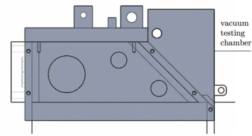
A-3 Back view of load lock system . . . 52
A-4 Vacuum testing chamber . . . 53
B-1 Calculation of radial loading on shaft and bearing wear . . . 56
B-2 Calculation of shaft bending . . . 57
B-3 Calculation of torque supported by keyway . . . 57
B-4 Calculation of torque to open . . . 58
B-5 Calculation of torque to close . . . 59
B-6 Calculation of chamber thickness and seal . . . 60
B-7 Calculation of door thickness . . . 61
List of Symbols
Ao area of contact with O-ring upon compression [m2]
Ap area of plate [m2]
a length of plate [m]
abend slope of end of plate under deflection [rad]
achord chord angle [rad]
ad angle of door [rad]
ae Abbe error of shaft [m]
al angle between pneumatic cylinder and linkage [rad]
b width of plate [m] bID bearing ID [m]
c vertical compression of O-ring [m] cp percent crush of cylinder [%]
D diameter of O-ring [m] Dh diameter of housing hole [m]
Di inside diameter of O-ring [m]
Ds diameter of shaft [m]
d1 distance from bearing 1 to door [m]
d2 distance from door to bearing 2 [m]
d3 distance from bearing 2 to driving linkage [m]
dedge tensile deflection of the plate edge [m]
dmax maximum deflection of plate [m]
Er elastic modulus of rubber [Pa]
Es elastic modulus of 1045 carbon steel shaft [Pa]
F force on cylinder against flat plate [N] Fa force from actuator [N]
Fb1 radial force on bearing 1 [N]
Fb2 radial force on bearing 2 [N]
Fc centripetal force from door [N]
Fl force per unit length [N/m]
Fo force on O-ring [N]
Fp force on plate [N]
H keyway depth [m]
hc half the length of contact [m]
I shaft bending moment of inertia [m4]
K specific wear amount [m/([N/m2][m/s][s])]
L approximate leak rate [mbar/s] Lk keyway effective length [m]
l linkage length [m] lb length of bearing [m]
lchord chord length [m]
lo total length of o-ring [m]
lsc lever arm from shaft to center of door [m]
md mass of door [kg]
P pressure differential [Pa]
Pc,max maximum contact pressure on bearing [Pa]
pae percent Abbe error of bearing ID [%]
pr permeability rate of gas through elastomer at the
operating temperature [s-bar]m2]
Q factor depending on percent squeeze and whether O-ring is dry or lubricated
S shore A durometer T time [s]
˙
V volume flow of air compressor [m3/s]
V1 intermediate variable for aluminum [N/m2]
V2 intermediate variable for rubber [N/m2]
vc velocity of pneumatic cylinder [m/s]
vt tangential velocity of shaft [rad/s]
tmin minimum thickness of plate [m]
tseal assumed thickness of the seal [m]
W wear on bearing [m] Wd door weight [N]
Wd,c component of door weight perpendicular to linkage
lever arm [N] Wk keyway width [m]
Y yield strength of material [Pa]
µ(x) moment on shaft [Nm] ⌫a Poisson’s ratio of aluminum
⌫r Poisson’s ratio of rubber
! angular velocity of driving linkage [rad/s] ⌧a torque provided by actuator [Nm]
⌧d torque required to rotate the door [Nm]
⌧o torque required to unstick O-ring [Nm]
⌧p allowable torque limited by contact pressure [Nm]
⌧s allowable torque before shear failure [Nm]
Chapter 1
Introduction
Lyophilization is a freeze-drying process in which the water within a sample is frozen and sublimated from solid state to vapor state. Along with other methods, it has often been used in the pharmaceutical industry to prepare vaccines. Whereas normal vaccines require specific storage temperatures, lyophilized vaccines do not, making them easier to transport and distribute [4].
An entire lyophilization process involves loading and filling of vials, condition-ing, nucleation, freezcondition-ing, drycondition-ing, unloadcondition-ing, and cleaning and sterilization. This has traditionally been done through batch processing. Conventional batch processing is human-driven, and hundreds of vials are manually moved throughout these stages. This introduces inefficiencies, especially when filling and loading such large batches. Key challenges include reducing dead time and keeping within the limits of homoge-nous heat transfer to each vial, given large batch sizes. There is not a lot of flexibility in process control either, as the product results only after hours of processing [8].
The overall goal of the current research is to apply continuous manufacturing tech-niques to lyophilization. Continuous manufacturing, which involves minimal human intervention, decreases dead time and uses small batches to increase productivity, flex-ibility, and process control. Decreasing manual labor means that the manufacturing process will be safer and more reliable.
To implement a continuous manufacturing process in lyophilization, the transition between different high-pressure and low-pressure processes needs to be taken into
account. Often used in the semiconductor industry, load locks are used as transition chambers to transfer wafers between high-pressure and low-pressure processes. A load lock will individually pump down or vent to match a pressure adjacent to its inlet door, allow the sample to move in, and then seal and pump down to match the adjacent pressure of its outlet door. When this is completed, the sample exits. Load lock systems are necessary in order to reduce pump-down and venting times in processing chambers [11].
This thesis will document the design of a load lock system and a test vacuum chamber for a continuous lyophilization machine. One load lock system is presented here; however, a second load lock system was designed in parallel by Ryan Flores and detailed in his undergraduate thesis. The vacuum testing chamber can be used to test both systems because it provides adequate attachment points for each. To observe inside the chamber, a zinc selenide lens assembly was designed by graduate student Ellen O’Connell.
1.1 System Architecture
The lyophilization continuous manufacturing machine, which is being developed by MIT, consists of vials containing unit-dose pharmaceuticals that are transported on flat top surfaces between different processes.
Because of the geometry of the overall system, there was no room for any sort of obstruction or lip to provide a sealing surface. However, it was possible to introduce a gap of up to 10 mm between the flat top surfaces. The system also required minimal particle generation. U.S. Pharmacopeia (USP) specification notes that for particulate matter in injections, the average particle count should not be greater than 600 per container, for a container greater or equal to 25 µm [2]. Therefore, sliding surfaces were avoided as much as possible. The system also needed to physically withstand the largest pressure differential of 1 atmosphere, which occurs between the freezing and drying phases.
From the system architecture, physical constraints, and sealing requirements, a set of design requirements were created:
1. Door seals to a flat surface
2. Door geometry minimizes particle generation
3. Actuation minimizes footprint and particle generation 4. System fits in overall machine
5. System meets speed requirements
6. Door stays sealed during pressure changes 7. Door does not deform under pressure
8. System allows selective access to samples (one side at a time) 9. System uses FDA-approved materials
1.2 Industry Load Lock Configurations
The semiconductor industry requires a standard of particle contamination which is much stricter than that needed for pharmaceuticals, so it serves as an appropriate starting point for comparison. The load-lock door designs that are relevant to the application in the semiconductor industry include a flapper valve, a gate valve, a parallel compression valve, and a L-motion valve.
A flapper valve involves the use of a rotating axle that attaches near one end of the door. In normal configurations, the flapper doors face seal against a flat surface parallel to the opening. Figure 1-1 represents the FlapVAT rectangular valve, which is one variation of a flapper valve that shows how it might be implemented [15]. One shortcoming of this configuration for the lyophilization application is that it requires a bottom lip to reliably seal to a vertical face.
Figure 1-1: Flapper valve
A gate valve involves a linear moving face that seals to a surface perpendicular to the direction of motion. In one variation of the gate valve, shown in Figure 1-2, the face is sealed at a 45o angle so that the actuator more easily holds the door in the
closed position under pressure [16]. When a pressure differential opposes the sealing direction, the 45o seal face does not require the actuator to provide as much sealing
force to counteract it, compared to a fully perpendicular seal face. However, a lot of space is taken up by this angled, linear actuator that would not be desirable in this application.
A parallel compression valve involves sealing to a flat surface parallel to the sample direction of motion, yet also requires a lip to create full seal face contact, as shown in Figure 1-3 [12]. This would place a moving column in the center, reducing the amount of space that the vials would have to pass through the load lock.
Figure 1-3: Parallel compression valve
Figure 1-4 shows a L-motion valve that combines the gate and parallel compression valves to take advantage of positive pressure and seal against the face [14]. The column moves vertically to position itself in front of the opening, and then pushes against the opening in a true L-motion. As the vacuum is created on the opposite side of the opening, the pressure differential helps to create a solid face seal. However, the L-motion valve would not fit in the 10 mm gap provided between the flat top surfaces for this application.
Figure 1-4: L-motion valve
These configurations could not be directly translated to the lyophilization appli-cation because the transport surface is flat and cannot have any protrusions on its surface. Instead, they were used as inspiration for creating a new design, which is the focus of this thesis.
Chapter 2
Mechanical Design
The current design of the load lock system was inspired by background research on the operations of a flapper valve, 45o angle gate valve, and L-motion valve. Using a
combination of rotary motion, like the flapper valve, and an angled sealing surface, like the 45o gate valve, an idea was developed for a door that rotates down to create
a static face seal to an angled front plate. Similar to the L-motion valve, the actuator only initiates the seal, and the differential pressure provided by pumping down the chamber helps to create a solid face seal. The door is actuated through a pivoting pneumatic cylinder and linkage to provide torque, and the test vacuum chamber, which includes a window and zinc selenide lens for thermal imaging, is RTV sealed to the flat top surface. Full assembly solid models in 3-D views are shown in Appendix A and full detailed calculations are in Appendix B.
2.1 Door Geometry
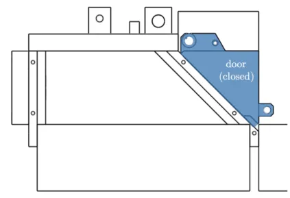
The door was placed such that the differential pressure provided the necessary sealing force. To create clearance along the length of the chamber, a triangular prism door design was used. Both closed and open door positions are shown in Figure 2-1 and Figure 2-2.
Figure 2-1: Assembly with door closed
Figure 2-2: Assembly with door open
Without the ability to have a protruded lip on the flat surface to create a full vertical face seal, an angled plane was necessary to create the seal, as shown in Figure 2-3.
Figure 2-3: Angled plane
For the full load lock system with two doors, this design, with the doors positioned in the same orientation to take advantage of differential pressure, requires two flat top surfaces. Figure 2-4 shows one door with one flat top surface, and it is clear that two doors in the same orientation would not fit without hitting the vial configuration.
Figure 2-4: Vial configuration spacing with one flat surface
The possibility of a double-wide instead of a single-wide door was also explored, but ultimately not pursued. The vials, in a rectangular configuration, must enter with the shortest side first due to movement limitations; therefore, the door cavity was crucial to the vials fitting in the load lock. Ideally, the double-wide door would have allowed two vial configurations to sit side-by-side, which is more efficient in the system. A single-wide door forces the vial configurations to enter the load lock one at
a time. However, the width limitations of the flat top surface and the corner round radius needed for the O-ring seal did not result in a wide enough opening for two of the vial configurations to pass through at the same time. The width of the door includes the following factors, depicted in Figure 2-5:
1. Clearance from wall to edge of door
2. Clearance from edge of door to o-ring groove 3. O-ring groove width
4. O-ring installed ID
5. Clearance for the vial configuration
Figure 2-5: Width considerations
Figure 2-6 shows the lack of clearance for a double-wide door, indicated by the negative total clearance to each side wall.
Figure 2-6: Calculation of clearance
It was not possible to achieve a double-wide door system, so a single-wide door system had to be used. To optimize efficiency in the single-wide case, the door opening was pushed as far to one side as it could go. This asymmetry eliminated the need for extra space to re-position the vial configurations in the middle before entering the load lock.
2.2 Elastomer Sealing
Creating a proper door seal involves both material selection and an understanding of how the O-ring compresses. Improper compression can lead to early fatigue of the seal, as well as increased seal leakage. Important parameters that were considered include material, percent squeeze, leak rate, installation ID, and installation bend radius [5].
The Parker O-Ring Handbook details examples of materials that satisfy different leak and gas compatibility parameters. In common load lock and vacuum chamber mechanisms, Butyl rubber (IIR), Fluorocarbon rubber (FKM), and Perfluorinated elastomer (FFKM) are often used for their relative impermeability, low off-gassing, and large range of working temperatures [13][7]. Given approved FDA material re-strictions and given our lowest operating temperature of -40oC, Ethylene propylene
diene rubber (EPDM) is a better option because it has a low working temperature up to -50oC, despite its slightly inferior impermeability and off-gassing capabilities [5].
However, for the purposes of rapid development of this prototype, a common Buna-N O-ring of durometer 70 was selected.
A static face seal was used to compress the O-ring, requiring metal-to-metal con-tact. In addition to recommendations to specify an O-ring installation ID that is 2%
smaller than the required diameter, a half dovetail groove, requiring 17% compression, was added to mechanically keep the seal in place [5]. While a typical half-dovetail groove has three walls, limited clearance at the bottom of the door meant that the non-dovetailed wall had to be removed for just that bottom section.
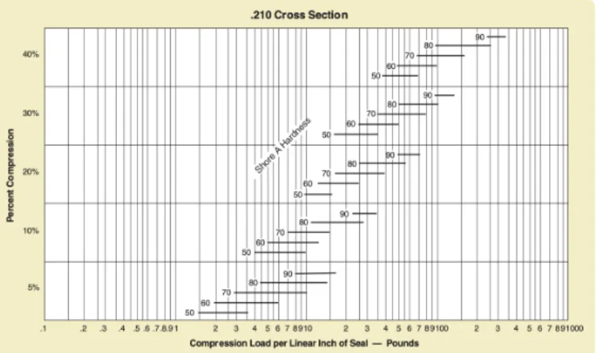
Gland depth, length, and percent squeeze were taken from recommendations for specified cross-sectional diameter in the Parker O-Ring Handbook. The Parker Hand-book contains a figure detailing estimated percent compression of different diameter O-rings based on the compression load per length of O-ring [5]. For this design, due to the 1 atmosphere pressure differential across the plate and an O-ring total length of 18.3", the O-ring load per inch was 21.7 lbs/in. Figures 2-7, 2-8, and 2-9 describe three consecutive common O-ring diameters: 1/8" (0.139" nominal), 3/8" (0.21" nominal), and 1/4" (0.275" nominal). With an O-ring of 70 Shore A durometer, only O-ring diameters 0.21" and above could achieve more than the 17% compression required for a half-dovetail groove.
Figure 2-7: Percent compression compared to compression load per inch of seal for a 0.139" diameter O-ring seal.
Figure 2-8: Percent compression compared to compression load per inch of seal for a 0.21" diameter O-ring seal.
Figure 2-9: Percent compression compared to compression load per inch of seal for a 0.275" diameter O-ring seal.
Although it is true that the compression is constrained by the specified groove depth to achieve 17% compression, this estimation was done to ensure that there would be enough compression in the first place, and to ensure that there was not excessive loading of the metal surfaces during face seal contact.
The physical swing clearance of the door to the next flat surface also constrained the size of the O-ring diameter because of the narrow 10 mm gap. Due to this physical constraint and the required percent compression, the 3/16" (0.21” nominal) diameter O-ring of durometer 70 was the only diameter O-ring that could work.
the installed inner radius of the O-ring is specified as 3 times its diameter [5]. Con-sequently, it was one of the factors influencing the single-wide door decision.
Leak rate was also estimated to ensure that the seal would work properly (Figure B-9). Leak rate was determined as adequate for a vacuum application, at 1.2E-05 mbar/s, through the leak rate equation [5]:
L = 0.7prDiP Q(1 cp)2 (2.1)
Figure 2-10: Calculation of leak rate
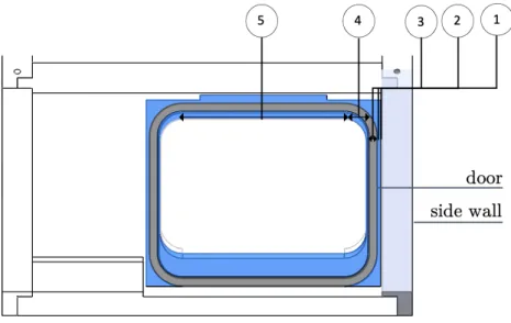
2.3 Test Chamber
The test chamber consisted of four walls that were bolted together and sealed with RTV sealant. A window allowed viewing of the samples, and a zinc selenide viewing port allowed for thermal imaging. An Edwards RV12, dual-mode, direct-drive rotary vane pump will provide the necessary vacuum for testing purposes [1]. To accommo-date this, two vacuum ports in the left chamber wall were placed, as shown in Figures
Figure 2-11: Vacuum testing chamber
Figure 2-12: Vacuum testing chamber with ports
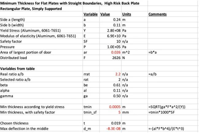
Determining the wall thicknesses of the chamber, door, and window was important because all components were going to be placed under a large pressure differential. Using Roark’s equations for a flat, simply supported rectangular plate, the maximum stress experienced by these plates of different materials was determined [9]:
From the area of the plate and the pressure differential, the distributed force against the plate was found:
Ap = ba (2.2)
From the ratio of a to b, a value was determined from the given table [9] and used to solve for the minimum thickness:
tmin =
r Fpb2
Y (2.4)
The calculation for the back plate of the vacuum chamber, which had the largest unsupported area, is shown in Figure 2-13 as an example. Similar calculations were done for the window and door, all of which are detailed in Appendix B.
Figure 2-13: Calculation of vacuum chamber wall thickness
Using the yield stress of 6061-T651 aluminum plate and glass, a large factor safety of over 10 was incorporated for each material. Based on these calculations, a wall thickness of 3/4” was chosen for the vacuum chamber, a thickness of 1/2” for the door, and a wall thickness of 3/8” was chosen for the window.
half-into account the pressure differential and using Figure 2-8 to confirm appropriate percent compression of the O-ring. The face seal was created by bolting into blind holes in the vacuum chamber back wall.
A non-permanent face seal concept was explored with one of the iterations of the chamber, as shown in Figure 2-14. The face seal was very difficult to achieve because the requirement that the minimum radius of the installed ring be 3 times the O-ring diameter would have forced the entire assembly to extend out far past the 10 mm gap.
Figure 2-14: Vacuum testing chamber with face seal
The location of the angled plane along the length of the flat surface affected its potential angle. Initially, the plane was placed slightly further back on the flat surface, as shown in Figure 2-15. This allowed the plane angle to be significantly smaller. However, the overall structure became more difficult to manufacture, and there was a concern that the O-ring would not be able to create a full seal under vacuum. Figure 2-16 shows that the seal needed to be compliant enough to transition between the angled face and the horizontal opening of the face. However, there was no straightforward way to go about this calculation.
Figure 2-15: Angled plane further back on flat surface
Figure 2-16: Difficulty in seal transition
To ensure that the chamber would seal properly, the angled plane needed to extend into the gap. The current iteration was based on making the vacuum chamber out of simple plates and placed the plane all the way to the front of the flat surface, allowing a solid RTV seal around the edges of the flat surface (Figure 2-3). Given the 10 mm gap clearance to the next flat surface, the angle of the plane had to be minimally 45o
to allow adequate clearance of the door to the next flat surface.
The tensile strain of the RTV silicone sealant was also found to prevent failure due to the deflection of the chamber walls under pressure, as shown in Figure 2-17. Roark’s equations for a simply supported rectangular plate aid in determining the maximum deflection of the plate in the center [9]. Strain was determined through the assumption that the deflection in the center of the plate was equivalent to the deflection at the edge of the plate.
dmax =
↵Fpb4
E3 a
(2.5)
The deflection at the center of the plate was assumed to be the same as the deflection at the end of the plate. This was used to geometrically find the tensile deflection and strain experienced by the silicone seal:
abend = tan-1(dmax
4
b ) (2.6)
dedge = t sin(abend) (2.7)
Using an experimental value for the strain failure of the RTV sealant [10], a large safety factor was found:
✏ = dedge
tseal (2.8)
Figure 2-17: Calculation of RTV sealant strain
2.4 Actuation
The actuation requirements state that there should not be particle generation from the actuator itself. This means that there needed to be either sealed containment, or as few sliding components as possible. Some actuators that were explored include
solenoid valves, hydraulic actuators, and pneumatic actuators. For this application, pneumatic actuators were chosen because they do not risk fluid leakage into the system, like hydraulic actuators. Rotary solenoid valves utilize three ball bearings, which introduces the risk of particle contamination.
Within the scope of pneumatic actuators, there are both linear and rotary actu-ators. A pneumatic rotary vane actuator, as shown in Figure 2-18, initially seemed like a good choice, especially since the system required rotational motion.
Figure 2-18: Pneumatic vane actuator assembly
However, after considering adjustability, a pivoting linear pneumatic cylinder was chosen in conjunction with a keyed linkage to create this rotary motion, as shown in Figure 2-19. The pneumatic cylinder was fixed through a pivot instead of a static nut and bolt to avoid side loading on the piston. Not only is the cylinder more cost-effective than a vane actuator, but it also allows greater adjustability in the test system; if a larger force is needed to break the seal, the piston can be swapped out to provide that.
When a seal is put under pressure, the actuator must provide enough torque to support opening and closing the door. The piston was placed to maximize the amount of torque upon opening by starting the opening motion at a 90o lever arm (Figure
Figure 2-19: Pneumatic linear actuator assembly
To help with sizing the current actuator, the exact amount of torque provided when the pneumatic cylinder is fully opened and fully closed was determined as 24.2 Nm and 18.1 Nm, respectively (Figure 2-20):
⌧a = Fasin(al)l (2.9)
2.4.1 Opening
When a seal is put under pressure, residual stick remains even after the system is vented, and the actuator must provide the torque to break it. There are two states that were considered upon opening the system:
1. The torque required to overcome the residual stick of the O-ring in the closed-door position
2. The torque to hold the door in the open-door position
For both cases, the torque needed to rotate the door, based on door weight, was calculated. First, the component of the weight perpendicular to the linkage lever arm was determined:
Wd,c = Wdcos(ad) (2.10)
Then, the torque required for both the first and second states was determined as 0.604 Nm and 0.427 Nm, respectively:
⌧d = = Wd,cl (2.11)
For the first state, the torque to overcome the residual stick was also approximated. The chord length was calculated assuming that the amount of residual stick was equivalent to 5% vertical squeeze of the O-ring. Then, the length of the O-ring was used to find its effective crush area. Assuming that the micropores of the O-ring were under the maximum door pressure of 1 atmosphere, the torque to lift the O-ring was
c = cp2r (2.12) achord = 2( r c r ) (2.13) lchord = = 2r sin( achord 2 ) (2.14) Ao = lchordlo (2.15) Fo = P Ao (2.16) ⌧o = lscFo (2.17)
In the first case, the torque required for overcoming residual stick and the torque required to lift the door were added to find the total opening torque of 5.2 Nm. In the second case, only the torque required to hold the door, 0.604 Nm, was needed. In the first and second states, given the torque provided by the actuator, safety factors of 4.7 and 30 were respectively calculated. Figure 2-21 details this calculation:
2.4.2 Closing
When closing the system, the actuator needs to provide adequate force to start the seal. This is because full sealing pressure does not occur until the vacuum chamber is pumped down completely. To start off the seal with 1% squeeze, the Parker O-Ring Handbook plot (Figure 2-8), was used to find estimated percent compression based on the compression load per length of a 3/8" (0.21" nominal) O-ring [5]. Figure 2-22 shows a plot created for percent compression based on compression load per length specifically for a 70 Shore A durometer O-ring. Based on the best-fit natural log, the necessary force per inch for 1% compression was interpolated as 2.6 lbs/in, for a total required force of 47.2 lbs, or 210 N along the length of the O-ring.
Figure 2-22: Percent compression compared to compression load per inch of seal for a 0.21" diameter, Shore A durometer 70 O-ring seal. The natural log fit equation is y = 0.1134ln(x)-0.0975. Plot values are taken from the Parker O-Ring Handbook.
From there, the torque required to close the door of 13 Nm, and its safety factor of 1.9 based on the torque provided, was found (Figure 2-23):
Figure 2-23: Calculation of torque to close
Another consideration when using this system was that the keyed part of the linkage needed to withstand the torque provided by the linear actuator. To account for this, both the allowable torque transmitted by the shaft and limited by contact pressure and the allowable torque transmitted before shear failure were found.
The allowable torque, limited by contact pressure, was calculated using:
⌧p = Y
D 2Lk
H
2 (2.18)
The allowable torque transmitted before shear failure was calculated using:
⌧s =
Y
1.7WkLk D
2 (2.19)
The minimum allowable torque, 49 Nm, was divided by the torque provided by the actuator, 24 Nm, in order to obtain a safety factor of about 2, as shown in Figure 2-24:
2.5 Bearing and Shaft
To determine shaft diameter, the amount of bending experienced by the shaft was found. Throughout this calculation, it was assumed that there were four contact points from the two bearings, door, and driving linkage. Although there is a third bearing, it was not counted because over-constraint is avoided through relatively large clearance for the bolts that secure the rectangular tube to the vacuum chamber right wall.
First, the radial force from the bearings were found through a force balance and a moment balance (Figure 2-25).
Figure 2-25: Free body diagram of radial force on shaft
The velocity of the cylinder was estimated through the volume flow of the air compressor and piston area [6]. From the driving linkage length, the angular velocity was found, and translated to the shaft tangential velocity using the shaft radius.
vc = 28.8 ˙V Ap (2.20) ! = vc l (2.21) vt = ! Ds 2 (2.22)
The radial force from the door was estimated as the centripetal force from the door. This, along with the weight of the driving linkage, was used to find the radial load on both bearings, with high safety factors. Figure 2-26 shows a summary of the radial force calculation:
Fc = mdvt2 lsc (2.23) Fb2 = Fcd1+ (d1+ d2+ d3)Wc d1+ d2 (2.24) Fb1 = Fc + Wc Fb2 (2.25)
Figure 2-26: Calculation of radial load on shaft
The radial load on the bearing, door, and driving linkage was needed to find the bending moment on the shaft. From the free body diagram, the moment experienced by the shaft was determined at each intermediate point. The maximum moment of 0.6 Nm was experienced by the shaft at the door location:
M (x) = 8 > > > > < > > > > : Fb1x, if 0 < x d1 (Frd Fb2)x, if d1 < x d2 (Fb1+ Fb2 Frd)x, if d2 < x d3 (2.26)
From the maximum moment, the maximum stress was found. A shaft diameter of 3/8" was chosen to decrease the amount of stress in the shaft and increase the safety factor: I = ⇡Ds 4 64 (2.27) max = | Mmaxds 2I | (2.28)
While considering the bending of the shaft, the Abbe error produced by the phys-ical bending was also found (Figure 2-26). This was important because keeping the Abbe error as less than 10% of the bearing ID preserves bearing life and ensures proper function without too much friction. Using the equations for a simply supported beam, the slope of the ends of the beam were calculated. Abbe error was determined over the length of the bearing, and compared to the bearing ID, to confirm that the error was 5.3E-02%, which is less than 10% of the bearing ID:
✓s = Frd1+ d22 16EsI (2.29) ae = tan(✓s)lb (2.30) pae = 100ae bID (2.31)
Figure 2-27: Calculation of bending moment and Abbe error
Bearing wear was also determined. Contact pressure on the bearing was found by making the assumption of negligible clearance and elastic housing and bearing material. The equation for contact pressure follows [3]:
Pc,max =
4Fb2
⇡lbDh (2.32)
Using this, the maximum PV value was determined. Finding the PV value also helped in calculating the amount of wear in the bearing as well. Archard’s equation was used in this context to provide a rough estimate of the amount of wear in the bearing: [3]:
P V = Pc,maxvt (2.33)
The calculated PV value, of 6.1E04 Ns/m, was confirmed as less than the spec-ification PV value of 7.4E04 Ns/m, which is important for maintaining bearing life. Additionally, minimal wear of 5.5E-02 mm was found, based on a sliding time of 300 hours. Figure 2-28 details the PV value and wear calculation:
Chapter 3
Future Work
In the future, this load lock system will be tested under vacuum pressure and actuated using an air compressor. The purpose of this testing will be to validate clearances and validate that the load lock system can properly seal while physically withstanding the pressure differential of 1 atmosphere. The actuator needs to be tested to ensure that it will provide enough torque to lift the door given the residual stick of the O-ring after applying and releasing the vacuum pressure. This is critical because the calcu-lated value of the torque to overcome the residual stick is based off of assumptions. The actuator also needs to be able to provide enough torque to initiate the seal with 1% crush. It will be connected through pneumatic tubing to a five-way, two position solenoid valve, which will then be connected to the air compressor. Since particle contamination is a concern, there will also be a particle count sensor inside the cham-ber to determine particles generated after opening of the load lock system.
The testing plan, once everything is assembled, is detailed below:
1. Connect inlet and outlet ports of vacuum chamber to vacuum pump
2. Attach pneumatic actuator tubes to air compressor
3. Insert particle count sensor
1 atmosphere pressure differential
5. Leave system under pressure for the amount of time the vials will be left in the load lock system
6. Vent the vacuum testing chamber and open the door 7. Take out particle count sensor and record
Based on what is learned from testing, modifications will be made to the existing system. It is likely that clearances and the size of the actuator will need to be optimized. Later on, the complete load lock system, which will be two flat top surfaces long, will be tested and integrated into the entire continuous lyophilization machine.
Chapter 4
Conclusion
The design of the load lock system for continuous lyophilization was inspired by current load locks in the semiconductor industry, but constrained by the physical limitations of the lyophilization machine, which is under development by the MIT research team led by Profs. Slocum and Trout. The system consisted of a triangular prism door that rotated onto a corresponding angled plate, which created a face seal. It sealed against a flat surface, given a small gap, and took advantage of differential pressure to provide adequate sealing force. RTV silicone sealant simplified the sealing from testing chamber to the flat top surface, and an asymmetrical single-wide door was selected for operational efficiency and acceptable clearance. Simultaneously, the specifics of the load lock system were calculated to allow more detailed design. An understanding of clearances in the system, sealing analysis, and torque analysis led to selecting the appropriate angle of sealing plane, O-ring, and actuator. Bearings, shafts, and wall thicknesses were also validated. The designed load lock system, once tested and optimized, will provide a relevant application of semiconductor technology to lyophilization and contribute to the development of the continuous manufacturing machine as a whole.
Appendix A
3-D Solid Models
This chapter provides more detailed 3-D solid models of the current load lock system design.
A.1 Load Lock System
Figure A-2: Right isometric view of load lock system
Figure A-3: Back view of load lock system
Appendix B
Calculations
This chapter details the design calculations done on the door, vacuum testing cham-ber, bearing, and shaft.
B.1 Shaft Radial Load and Bearing Wear
This calculation was used to find the radial load on the shaft and a maximum PV value based on the contact pressure of the bearing and the velocity of the shaft. This maximum PV value was compared to the given maximum PV value and confirmed that it stayed below this limit. Bearing wear was also calculated here (Figure B-1).
Figure B-1: Calculation of radial loading on shaft and bearing wear
B.2 Shaft Bending
This calculation was used to find the maximum bending stress on the shaft, comparing it to the shaft yield stress. The Abbe error resulting from bending was less than 10%
Figure B-2: Calculation of shaft bending
B.3 Torque Supported by Keyway
This calculation identified the maximum torque that could be supported by the key-way, and was used to design the appropriate length of the keyway. A safety factor of 2.0 was found when comparing maximum torque supported to maximum torque provided by the linear pneumatic actuator (Figure B-3).
B.4 Torque to Open
This calculation was used to find the torque necessary to open the door and overcome door weight and the residual crush of the O-ring. The torque provided by the actuator was found at the open and closed states and used to find a safety factor (Figure B-4).
B.5 Torque to Close
This calculation was used to find the torque necessary to close the door and start the seal with 1% crush (Figure B-5).
B.6 Chamber Thickness and Sealing
This calculation was done to determine chamber thickness based on the pressure differential. It also confirmed that the RTV silicone sealant will likely not fail under minimal deflection of the chamber wall under pressure (Figure B-6).
B.7 Door Thickness
This calculation was done to determine door thickness based on the pressure differ-ential and confirmed a large safety factor compared to yield strength (Figure B-7).
B.8 Window Thickness
This calculation was used to find appropriate window thickness given the pressure differential. A large safety factor was found compared to yield strength (Figure B-8).
Figure B-8: Calculation of window thickness
B.9 Seal Leak Rate
This calculation was used to determine approximate leak rate of the door seal under the pressure differential. The leak rate was shown to be on the order of magnitude appropriate for vacuum applications (Figure B-9).
B.10 Double Wide Door Calculation
Contributed by Prof. Slocum, this calculation detailed the clearance and minimum width of the vial configuration, and showed that the double-wide door could not be feasible due to physical dimensions (Figure B-10).
Bibliography
[1] Edwards Pump Manual, December 2009. [2] <788> Particulate Matter in Injections, 2012.
[3] J. F. Archard. Contact and Rubbing of Flat Surfaces. Journal of Applied Physics, 24(8):981–988, August 1953. Publisher: American Institute of Physics.
[4] Luigi C. Capozzi, Bernhardt L. Trout, and Roberto Pisano. From Batch to Con-tinuous: Freeze-Drying of Suspended Vials for Pharmaceuticals in Unit-Doses. Industrial & Engineering Chemistry Research, 58(4):1635–1649, January 2019. [5] Parker Hannifin Corporation. Parker O-Ring Handbook, 2018.
[6] Engineering ToolBox. Pneumatic Cylinder Velocity.
[7] Nathanael Reis. Semiconductor FFKM Offers Low Particle Generation and Ex-treme Etch Resistance, June 2018. Library Catalog: community.parker.com. [8] Roberto Pisano, Andrea Arsiccio, Luigi C. Capozzi, and Bernhardt L. Trout.
Achieving continuous manufacturing in lyophilization: Technologies and ap-proaches. European Journal of Pharmaceutics and Biopharmaceutics, 142:265– 279, September 2019.
[9] Raymond J. Roark, Warren C. Young, and Richard G. Budynas. Roark’s formu-las for stress and strain. McGraw-Hill, New York, 7th ed edition, 2002.
[10] Yves Staudt, Christoph Odenbreit, and Jens Schneider. Failure behaviour of silicone adhesive in bonded connections with simple geometry. International Journal of Adhesion and Adhesives, 82:126–138, April 2018.
[11] Takako Takehara, Sheng Sun, and M. White. Hybrid PVD-CVD System, January 2007.
[12] Takayuki Matsumoto and Shinichi Kurita. Control of Slit Valve Door Seal Pres-sure, December 2008.
[13] Trelleborg Sealing Solutions. Semiconductor Sealing Solutions, 2008. [14] VAT. Large door L-VAT.
[15] VAT. Rectangular valve FlapVAT, May 2020.
[16] Wendell Blonigan, Emanuel Beer, Jaime Munoz, and Sam H. Kim. Slit Valve Method and Apparatus, March 2006.