Design and Control of a Voice Coil Actuated Robot Arm for Human-Robot Interaction
by
John M. McBean B.S. Mechanical Engineering
Massachusetts Institute of Technology, 2001
SUBMITTED TO THE DEPARTMENT OF MECHANICAL ENGINEERING IN
PARTIAL FULFILLMENT OF THE REQUIREMENTS FOR THE DEGREE OF MASTER OF SCIENCE IN MECHANICAL ENGINEERING
AT THE
MASSACHUSETTS INSTITUTE OF TECHNOLOGY JUNE 2004
@ 2004 Massachusetts Institute of Technology All rights reserved
Signature of Author...
C ertified by...
Department of Mechanical Engineering May 7, 2004
...
Cynthia Breazeal Assistant Professor of Media Arts and Sciences Thef6Supervisor Approved by...
Woodie Flowers Pappalardo Professor o echanical Engineering Mecha ing Faculty Reader A ccepted by ... ...
Ain Sonin Chairman, Department Committee on Graduate Students
BARKER
MASSACHUSETTS INSTI")E.
OF TECHNOLOGY
Design and Control of a Voice Coil Actuated Robot Arm for Human-Robot Interaction
by
John M. McBean
Submitted to the Department of Mechanical Engineering on May 7, 2004 in Partial Fulfillment of the Requirements for the Degree of Master of Science in
Mechanical Engineering
ABSTRACT
The growing field of human-robot interaction (HRI) demands robots that move fluidly, gracefully, compliantly and safely. This thesis describes recent work in the design and evaluation of long-travel voice coil actuators (VCAs) for use in robots intended for interacting with people. The basic advantages and shortcomings of electromagnetic actuators are discussed and evaluated in the context of human-robot interaction, and are compared to alternative actuation technologies. Voice coil actuators have been chosen for their controllability, ease of implementation, geometry, compliance, biomimetic actuation characteristics, safety, quietness, and high power density. Several VCAs were designed, constructed, and tested, and a 4 Degree of Freedom (DOF) robotic arm was built as a test platform for the actuators themselves, and the control systems used to drive them. Several control systems were developed and implemented that, when used with the actuators, enable smooth, fast, life-like motion.
Thesis Supervisor: Cynthia Breazeal
ACKNOWLEDGEMENTS
My thesis is dedicated to my family. Thanks for the support and inspiration.
Thanks for pushing me just hard enough. Thanks for the encouragement, and for the selfless enthusiasm. I am a fortunate son. And a grateful one.
Cynthia, it has been a pleasure working with you. Thank you for giving me such a perfect research opportunity, with the freedom to pursue a new idea, and the trust
that it had potential. My graduate career could not have been better. And congratulations on your newest family member. I wish you all the best!
Woodie Flowers, the past several years would have been very different had we not started arguing about catapults 3 years ago. I'm terribly lucky to have gotten in your way by convincing you that I was a liability. Thanks for asking tough questions, and giving credit to my answers. I have learned so much from you.
Fred Cote in the Edgerton Center Machine Shop. While I owe it to you,
it would be an insult to say thanks just for the machining education. I thank you for making it fun, keeping me on my toes, entertaining me, and teaching
me about more important things than machining. It has been enlightening. Thank you Leslie Regan for all of your help in pulling this together.
This research is the work of the Robotic Life Group and the MIT Media Laboratory. The work is funded by the Digital Life and Things That Think consortia.
OUTLINE CHAPTER 1. Introduction ... 10 1.1 Thesis Outline ... 11 1.2 M otivation... 12 1.3 Thesis Scope ... 16 CHAPTER 2. Background... 17
2.1 Robotic Actuator History ... 17
2.2 Voice Coil Actuator Technology and Prior W ork ... 21
2.2.2 Voice Coil Actuators for Human-Robot Interaction... 22
CHAPTER 3. Voice Coil actuator design ... 24
3.1 Detailed Description of VCA Design... 24
3.2 Specifications... 28
3.2.2 Cost... 30
3.2.3 Efficiency ... 31
CHAPTER 4. Arm Design ... 32
4.1 M echanical Design ... 32
4.2 Actuation and Feedback... 34
4.3 Electrical and Control Hardware ... 35
CHAPTER 5. Kinem atics and Dynam ics... 38
5.1 Kinem atics ... 38
5.2 Dynam ics ... 39
5.2.1 Actuator Constants... 40
5.2.2 Effective Actuator Attachm ent Radius ... 42
5.2.3 Inertial and Gravitational Effects... 43
5.2.4 Viscous Damping ... 43
5.2.5 Electrical Dynam ic M odel... 43
CHAPTER 6. Control System Design... 44
6.1 Overview ... 44
6.2 PID Control System ... 44
6.3 PID Control with Gain Scheduling ... 46
6.3.2 Position-Dependant A ctuator Constants... 48
6.3.3 Gravitational Effects ... 48
6.3.4 Varying Radius At Which The VCA Acts on Arm Segment ... 49
6.4 Model-Based Control System with PD Feedback ... 49
CHAPTER 7. Results ... 52 7.1 A ctuator results... 52 7.1.1 Perform ance... 52 7.1.2 Shortcom ings... 55 7.2 Arm Results ... 55 7.2.1 Interactivity ... 55 7.2.2 Strength ... 55
7.3 Overall System Results (w ith controllers)... 56
7.3.2 Results with PID controller with Gain Scheduling... 59
7.3.3 Results with Model-Based Feedforward controller with PD feedback .... 61 CHAPTER 8. Future Work and Conclusion... 66 8.1 Future W ork ... 66
LIST OF FIGURES
CH A PTER 1. Introduction ... 10
Figure 1.1 Robotic Life Group's robot, Leonardo ... 13
Figure 1.2 Leonardo w ith his fur... 14
Figure 1.3 Closeup view of Leo's gearmotor-driven upper arm... 15
CH A PTER 2. B ackground... 17
Figure 2.1 Basic voice coil consisting of magnetic assembly and moving coil... 21
CHAPTER 3. Voice Coil actuator design ... 24
Figure 3.1 Early prototype of radial field, square cross-section voice coil... 24
Figure 3.2 Solid model of radial voice coil... 25
Figure 3.3 Solid m odel of axial voice coil. ... 26
Figure 3.4 Sectional view of the moving-magnet, axial VCA used in the wrist.... 27
Figure 3.5 Bicep and forearm voice coil actuators... 28
Figure 3.6 Solid model of parallel stacked voice coil actuator ... 30
Figure 3.7 Measured zero-velocity holding power for the voice coil actuators... 31
CHAPTER 4. Arm Design... 32
Figure 4.1 Solid model of 4 degree of freedom direct-drive arm... 32
Figure 4.2 Photo of clevis bearing preload technique ... 33
Figure 4.3 Photo of elbow joint springs for gravity compensation... 34
Figure 4.4 Photo of motor drivers and control hardware ... 35
Figure 4.5 Photo of the arm ... 36
Figure 4.6 Photo of a person interacting with the arm... 37
CHAPTER 5. Kinematics and Dynamics ... 38
Figure 5.1 Schematic of kinematic arm structure ... 38
Figure 5.2 Plot of position dependancy of wrist actuator constant ... 40
Figure 5.3 Linearization of position dependancy of wrist actuator constant ... 41
Figure 5.4 Schematic of position dependency of actuator attachment radius... 42
CHAPTER 6. Control System Design... 44
Figure 6.1 Block diagram of PID controller for 4DOF arm... 45
Figure 6.2 Block diagram of wrist PID controller... 45
Figure 6.3 Block diagram of 4DOF PID control system with gain scheduling ... 47
Figure 6.4 Block diagram of model-based controller with PD feedback... 50
C H A PTER 7. R esults ... 52
Figure 7.1 Plot of forearm and bicep actuator force performance ... 53
Figure 7.2 Upper arm roll tracking performance with PID control (9 rads/sec)... 57
Figure 7.3 Forearm roll tracking performance with PID control (9 rads/sec)... 57
Figure 7.4 Plot of elbow tracking performance with PID control (9 rads/sec)... 58
Figure 7.5 Plot of wrist tracking performance with PID control (9 rads/sec)... 58
Figure 7.6 Plot of upper arm roll tracking performance with PID controller with gain scheduling (9 rads/sec)... 59
Figure 7.7 Plot of forearm roll tracking performance with PID controller with gain scheduling (9 rads/sec)... 60
Figure 7.8 Plot of elbow tracking performance with PID controller with gain scheduling (9 rads/sec)... 60
Figure 7.9 Plot of wrist tracking performance with PID controller with gain
scheduling (9 rads/sec)... 61
Figure 7.10 Wrist actuator tracking performance with PD control, 40 rads/sec... 62 Figure 7.11 Plot of wrist actuator tracking performance with feedforward and
feedback control, 40 rads/sec... 62
Figure 7.12 Plot of wrist actuator step response with simple PD control... 63 Figure 7.13 Plot of wrist step response with feedback and feedforward control... 64 Figure 7.14 Plot of wrist actuator tracking performance with feedforward and
feedback control, 80 rads/sec... 65
CHAPTER 8. Future Work and Conclusion... 66
LIST OF TABLES
CHAPTER 1. Introduction ... 10
Table 1.1 Actuator functional requirements and corresponding characteristics... 16
CHAPTER 2. Background... 17
Table 2.1 Actuator synopsis... 18
CHAPTER 3. Voice Coil actuator design ... 24
Table 3.1 Actuator Parameters... 28
CHAPTER 4. Arm Design ... 32
Table 4.1 Arm design parameters ... 33
CHAPTER 5. Kinematics and Dynamics ... 38
CHAPTER 6. Control System Design... 44
Table 6.1 Arm and actuator design parameters relevant to wrist control system d ev elop m en t... 5 1 CHAPTER 7. Results ... 52
Table 7.1 Actuator performance results... 54
CHAPTER 1. INTRODUCTION
The field of robotics is growing rapidly, and its demands are widespread. Robotic systems are typically comprised of mechanical hardware, electrical hardware, sensors, actuators, and computers. In a myriad of different applications, robots sense information about their own state as well as their environment, process that information, and act within their environment to accomplish a goal. The diverse environments in which different types of robots operate impose widely varying requirements in terms of the quality, speed, accuracy, robustness and type of sensing, actuation and processing
employed. Consequently, the selection of appropriate sensing, actuation, and processing technology for a robot is generally environment and application dependent. This thesis investigates the selection of an actuator technology that pertains specifically to robots designed to operate in environments where their primary goals involve interaction with people. In the ideal case of a robot as a collaborator with a person, there must be an effective information exchange between the person and the robot, as well as the effective execution of the task at hand (if the task consists of something more than the interaction itself). To fulfill these expectations, it is important for a robot to be able to convey and perceive visual, auditory and tactile information, as well as to interact with and affect its environment. This thesis addresses the implications of these requirements on the design, selection and control of robotic actuators.
Since robots find use in areas ranging from microscopic-scale precision assembly to dinosaur-sized amusement park monsters, there are nearly as many metrics for
evaluating actuator technologies as there are applications for them. Some typical metrics for comparing robotic actuators are: strength, response speed, accuracy, robustness to environmental conditions, durability (number of cycles to failure), mass, size, ease of implementation, cost, controllability, sound, stiffness, form factor, safety and scalability [2]. Currently, the majority of robots in operation are used in industrial environments. Spray painting, welding, and pick and place assembly are examples of typical robot applications. As such, the consideration of the interaction between robots and humans (if considered at all) is generally limited to safety and ease of control of the robot by the operator. Further, the actuator selection parameters are very different from those considered for human-friendly, collaborative robots.
The actuator criteria imposed by robots intended for meaningful and useful
interaction with humans differ significantly from those imposed by industrial robots. Our primary concern for such robotic actuators is quality of motion. For a rich and effective
human-robot interaction, robots must move smoothly, fluidly, and quietly. The motion must be fast enough to make the interaction or the task execution unencumbering and practical, while maintaining a slow enough pace that the human can keep up. The motion must be compliant enough that physical contact between the human and the robot is not
dangerous or uncomfortable. Further, it may be important that the human be able to physically guide the robot (in teaching the robot a task or a motion, for example), in which case the robot's motion must be controllable in such a way that it is aware of, robust to, and sympathetic to the touch of a person. This calls for actuators with low mechanical impedances and variable stiffnesses that are readily force-controlled. For certain applications it may also be important that the motion be convincingly organic, as the rigid, precise motion of an industrial robot may not be desirable in a robot intended as
an entertaining companion for a human. In the case of robots of human or mammalian form, the geometry of the actuators may also play an important role in their selection. If the physical appearance, as well as the quality of motion, is to be convincingly organic, actuators must be designed with sizes and shapes that fit seamlessly into organic forms. Comparisons of robot actuator technologies typically reveal the appealing high power densities of electromagnetic actuators, and the high pressures of hydraulic, piezoelectric, shape memory alloy (SMA), and certain electro-active polymer (EAP) actuators [1]. The conventional metrics of comparison for these actuators tend not to clearly identify which technologies are most suitable for high degree of freedom robots intended for tactile interaction with people. Such comparisons also tend to be misleading in that they may overlook some of the bulky infrastructure required for the
implementation of the actuators. Hydraulic actuators, for example, are particularly attractive for their high pressures, low power holding forces, and relatively high speeds. It should not be overlooked, however, that hydraulic actuators are conventionally messy, high maintenance, very stiff, and require large amounts of material overhead for pumps, fluid lines, valves, accumulators and the like. In the selection and development of an appropriate actuation technology for interactive robots, we have considered conventional metrics of comparison (pressure, power density, and controllability), while giving careful attention to the actuator demands that are specific to the field of human-robot interaction (HRI). In short, these demands include quality of motion, quality of tactile interaction, safety, form factor, noise level, robustness to overloading, and ease of implementation and control.
Electromagnetic voice coil actuators (VCAs) show great promise to fulfill many of the aforementioned requirements. They have high power densities, silent operation, smooth, backlash-free motion, variable stiffness, relatively low cost, favorable form factor, and are easily controlled. This thesis covers the design, implementation, control, and evaluation of VCAs as robotic actuators.
1.] THESIS OUTLINE
We begin in chapter 1 by discussing the requirements imposed on robotic actuators by different fields, and examining the actuator requirements imposed by our specific project within the field of HRI. This serves as the motivation for this thesis. In chapter 2, we discuss the background of robotic actuators, as a means of establishing baselines for comparison across many actuator metrics. We then introduce the work being done on voice coil actuators. We discuss the attributes of voice coil actuators, their
advantages and shortcomings (specifically in the context of tactile human-robot
interaction), and design parameters that affect their performance. We also describe prior work in the field of VCA technology. In chapter 3, we discuss more specifically the
design and construction of our VCAs. We discuss the tradeoffs in VCA design among size, form factor, quality of motion, mass, cost, and controllability. In chapter 4 we describe the implementation of the actuators in a 4 DOF robotic arm to be used in the development of a collaborative robot. In chapter 5, we describe the kinematic and dynamic modeling of the actuators and the arm. Chapter 6 is a discussion of the control system design. We discuss the necessity of an adequate control system to take full advantage of the actuator characteristics, and describe the different methods employed.
In chapter 7 we present the results. We discuss actuator performance, implementation issues, advantages and shortcomings of the mechanical design, compatibility of the components, control system performance, and overall system performance. Finally, in chapter 8, we discuss conclusions and future work. We describe the overall potential of VCAs as viable robotic actuators, as well as potential avenues of research for solving some of the fundamental problems with VCAs. We describe possible developments to ease their implementation and configuration, making them more effective and attractive as replacements for conventional actuators.
1.2 MoTIVATiON
The Robotic Life group at the MIT media lab works on developing robots that are socially, intellectually, and physically capable of interacting and collaborating with humans. Currently, the robot used for the implementation and evaluation of the research is Leonardo, a 66 degree of freedom expressive robot that stands approximately 70 centimeters tall. As can be seen in figure 1.1, Leonardo has a mammalian form factor, with a skeletal and muscular structure resembling that of a small child. He is a non-mobile robot, with the majority of his actuators located on his body. The larger actuators are located in the box on which Leonardo stands, and drive the joints via cables or linkages. All of Leonardo's actuators are brushed DC motors with gearboxes, using potentiometers and magnetic encoders for position and velocity feedback.
Vigure 1.2 Leonardo with his fur
DC motors have high volumetric power densities and low output torques.[l] As a
result, DC motors may be significantly smaller than human muscles to achieve similar power outputs for a given joint. However, these high power outputs are achieved at high speeds and low forces, necessitating large transmission ratios to attain the torques
demanded by robotic applications. Unfortunately, the use of such transmissions usually implies the introduction of backlash, noise, bulk, mass, excessive stiffness, torque ripple, and susceptibility to breakage. The peak torques achievable in small scale robotic
applications (like Leo) are generally limited by the strength and robustness of the
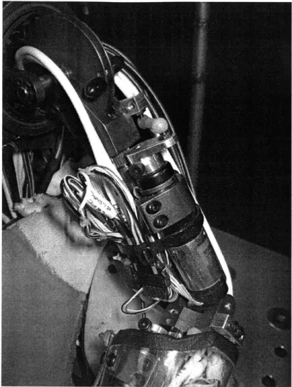
materials used in the gear train, rather than the ability of the motor to transform electrical power into mechanical power. Such is the case with Leonardo's actuators. Most of Leonardo's actuators have gear trains (see figure 1.3) with high ratios so that his joints are effectively infinitely stiff (non-backdriveable) as viewed from his workspace.
Figure 1.3 Closeup view of Leo's gearmotor-driven upper arm
The implication is that smooth, safe contact between Leo and his environment (people and objects) is difficult at best. Fluid, jitter-free motions at human-scale velocities and accelerations are unachievable. Sudden forces exerted on Leo by people or objects in his environment result in damage to his joints or his actuators. Tactile interactions with Leo are rigid, unforgiving, and slow.
There is an obvious need for an improvement in the actuators used in robots such as Leo, if they are to convey and interpret information effectively and exhibit a life-like presence. Table 1.1 presents the general functional requirements that we have chosen as being the most important in the development of actuators for a collaborative HRI robot. The table lists specific actuator characteristics that will be necessary to achieve the functional requirements.
Table 1.1 ACTUATOR FUNCTIONAL REQUIREMENTS AND CORRESPONDING CHARACTERISTICS
Functional Requirement Actuator Characteristics
High Quality of Motion -low backlash
-low coulombic friction/stiction -low mechanical impedance -moderate accelerations attainable -inherent damping
High Quality of Tactile -variable stiffness
Interaction -force or impedance controlled -adequate strength
Safety -high permissible control system gains -low inertia
-high compliance
-force or impedance sensing means
Organic form factor -moderate power and force density (to minimize actuator size)
-bilateral, push/pull actuation (to eliminate necessity of opposed pairs)
-linear, as opposed to rotary actuators (to mimic muscle) -small or no mechanical transmissions (minimize bulk) Quiet operation -few moving parts
-low or no transmission ratios (eliminate high speed mechanical contact)
Robustness to overloading -few mechanical parts. -backdriveable
-high compliance
Easy to implement and -minimize need for complex gear trains to change the
control actuation direction
-use readily available materials -low hysteresis
1.3 THESIS SCOPE
Leo needs new actuators. The goal of this thesis was to research, design and construct voice coil actuators that will serve as viable replacements for the conventional actuators used in robots such as Leo. We have designed and built a 4 degree of freedom arm as an evaluation platform for the new actuators, and as a potential model arm for the next generation of Leonardo. We also developed and evaluated control systems that exploit the actuators' favorable characteristics to improve robot performance in the areas where Leo is deficient.
CHAPTER 2. BACKGROUND
2.1 ROBOTiC ACTUATOR HiSTORY
In this section we give an overview of the state of the art of robot actuator technology. A comprehensive comparison of actuator technologies was published by Hollerbach, Hunter, and Ballantyne in 1992 [1] and is still very much relevant today. The vast majority of actuators used in robotic systems to date employ one or more of the technologies described in that paper. Many of these technologies have been proven to be robust, cheap, and readily available. Under a paradigm where robots are expected to be bulky, dangerous, rigid, precise, and serve strictly industrial applications, many of these conventional technologies excel. A recent push for biologically-inspired robots that interact directly with humans has spurred much research in artificial muscles. Many of these younger, biomimetic materials-based actuation technologies are beginning to provide competition for conventional technologies as robotic actuators [2], [3], [7].
First, we will define some terms that will be used in the discussion of the different actuation technologies. Power density is the amount of mechanical power output an actuator can produce, normalized by its mass or volume. Mass power density is
measured in Watts per kilogram; Volume power density is measured in Watts per cubic meter. Peak pressure is the maximum force an actuator can produce, divided by the
cross-sectional area of the actuator. Pressure density is the peak pressure attainable by the actuator, normalized by its mass or volume. Maximum strain is the maximum percentage by which the actuator can change its length while producing a force.
Efficiency refers to the overall energy conversion efficiency - the mechanical output
power of the actuator divided by the power input to the actuator (electrical, chemical, or thermal). Finally, work density is the amount of work generated over one full cycle of an actuator, divided by the actuator mass.
The following table comprises a combination of our own work and research, as well as that of Madden, Hollerbach, Hunter, and Ballantyne [1], [2]. Attempts to make fair comparisons of actuator technologies can be misleading, as universal metrics for evaluating performance are difficult to find, and often do not take into full account all of the components of the actuators. For example, note that no units have been chosen for the comparison of the speeds of the different types of actuators. This is because a
rigorous experiment has not been conducted where each of the actuators is subjected to a comparable speed or frequency response test; hence the speeds of the actuators are loosely characterized and described in the table. Other examples of the potentially misleading nature of actuator comparisons are the apparent high pressure and power densities of hydraulic and pneumatic actuators. Conventionally, this evaluation neglects the mass of the material overhead (pumps, valves, fluid lines, etc). This is acceptable only for very high DOF robots, where the mass and volume of the material overhead is in fact small compared to the overall mass of the system). We have attempted to highlight, where possible, such ambiguities in actuator comparison. Further, we have made attempts to describe the actuator characteristics that are especially relevant to HRI robot design.
Table 2.1 ACTUATOR SYNOPSIS
Technology Description
Mammalian Moderate peak stress (0.35 MPa)
Muscle Moderate strain (20%)
Moderate power density (50W/Kg) High (and variable) compliance Flexible form factor
Produces smooth, fluid motion Low material overhead
Low-moderate pressure density Moderate speeds
Unilateral (Pull-only) actuation
Inefficient at zero-velocity (holding) forces.
Electromagnetic Low peak stress (0.05-0.1 MPa)
(VCAs) Large strain (50%)
High power density (200 W/Kg)
Efficiency varies from high (-90%) at high speeds and short strokes to low (~5%) at low speeds and high stroke lengths
Fast
High compliance
Form factor compatible with human-form design Produce smooth, backlash-free, quiet motion Low material overhead.
Few moving parts; robust to overloading Bi-directional (push-pull) actuation
High force applications require mechanical transformers
Hydraulic High peak stress (20 MPa) Large strain (50%)
High power density (600 W/Kg) (difficult to account for material overhead mass, and extremely high instantaneous power delivery) High stiffness
Very high material overhead (valves, lines, pump, accumulator, filters, etc)
High maintenance Bilateral actuation
Moderate-high speeds (although inefficient at high speeds)
Pneumatic Moderate peak stress (0.7 MPa) Large strain (50%)
High power density (200 W/Kg) (difficult to account for material overhead mass, and extremely high instantaneous power delivery) High efficiency (-90%)
Pneuamatic (cont'd)
Piezoelectric
control difficulty. Moderate compliance High material overhead Bilateral actuation Often loud
High peak stress (35 MPa) Low strain (1%)
Very low power density (0.1 W/Kg)
Very high speeds (high frequency, very short stroke actuators - less practical for robotic applications)
Moderate material (and control) overhead Must be driven with high voltages
Quiet
Bilateral actuation
"Inchworm" and "Waverotor"- type actuators have been developed with larger strains and lower stresses
Magnetostrictive High peak stress (10 MPa)
Low strain (2%)
Very high power density (5 W/Kg) High efficiency (~80%)
High speeds are possible
Usually unilateral actuation
High material overhead (bulky magnets or coils are required for activation)
NiTi Shape- Very high peak stress (200 MPa)
Memory Alloy Low strain (1-8%)
(Thermal) Very high power density (100kW/kg) Very low efficiency (<5%)
Very difficult to control
Slow
Low voltage activation Low cycle life
Unilateral actuation
Can have good form factor for mammal-form robots Dielectric Moderate-high stress (1-10 MPa peak)
Elastomers Moderate-large strains (20%-380%) Moderate efficiency (15%-90%) Fast
Require high voltages Unilateral actuation
High material overhead (Pre-stretching mechanisms required)
Relaxor or High stress (45 MPa) Ferroelectric Low strain (<7%)
Polymers High work density (<lMJ/m3)
Relaxor or Ferroelectric Polymers (cont'd) Liquid Crystal Polymers Exhibits hysteresis
High driving voltages (>1kV) Unilateral actuation
Large material overhead (power supply, control electronics) Low-moderate stress (0.01-0.45 MPa)
Moderate-high strains (2%-45%, depending on whether thermal or field induced strain)
Moderate-high efficiency Difficult to control (creep) New material
High driving voltages
Slow
Conducting High stress (5-34 MPa)
Polymers Low strain (2%)
High stiffness
Low driving voltage (-2V) High work density (IOOkJ/m 3)
Slow
Bilateral actuation Low efficiency
Molecular Moderate-high stress (>1 MPa) Actuators Moderate-large strain (20%)
High work density (IOOkJ/m3)
Low driving voltage (-2V)
Slow
Unilateral actuation New technology
Carbon High stress (>1OMPa)
Nanotubes Very small strain (0.2%) Low driving voltage (-2V) Inefficient
Unilateral actuation Expensive
Ionic Polymer Large strain
Metal Low driving voltage (<1 OV) Composites Unilateral actuation
(IPMC) Low efficiency
Ferromagnetic High stress (<9 MPa) Shape Memory Small strain (<10%)
Alloys Fast
High efficiency Unilateral actuation
High material overhead (field magnets) ,
2.2 VoicE CoiL ACTUATOR TECHNOLOGY AND PRIOR WORK
Voice coil actuators have been around for decades. They have been used
primarily as the sources of force in audio loudspeakers, and as drive mechanisms for disk drive read heads. As described in Section 2.1, they are characterized by high power densities, high bandwidths, and relatively low pressures. A voice coil (see figure 2.1) is an electromagnetic actuator that generally consists of one or more coils of wire placed in a magnetic field, such that there is a force is produced when current flows in the coil. The voice coils discussed in this thesis use permanent magnets as the magnetic field
source.
isic voice coil consisting of magnetic assembly and moving coil
The force produced by the actuator (the voice coils described in this thesis are linear, rather than rotary actuators) is given by:
F = nrdiBSinO; (1)
where n is the total number of coils of wire, d is the average diameter of the coil, i is the current in the wire, B is the magnetic field strength, and ? is the angle between the magnetic flux lines and the direction of the current. The part of the actuator that moves,
and to which the load is attached is generally called the rotor, and the stationary part (in this case, the part which houses the coils) is called the stator.
Focus areas for improving the force outputs of VCAs are evident from (1). Square wire has been used to increase coil winding density (increasing n for a given volume). Attempts to increase the currents thermally permissible in the coils include development of low resistance coil materials, use of active cooling techniques [1], and the use of ferromagnetic fluid suspended in the air gap between the coil and the magnet.
Since heat adversely affects that magnetic field strength of permanent magnets
(especially NdFeB), the benefits of increased heat dissipation are twofold. Much work has been done to increase the magnetic field strength across the air gap. Permanent magnet materials, such as NdFeB, with higher magnetic remanences and higher
temperature tolerances have been developed. Actuator geometries have been refined so as to "focus" the flux in the air gap and minimize leakage [5]. The use of ferromagnetic fluid also increases the field strength and uniformity, but its effects are limited due to its low magnetic saturation. The preceding techniques have been shown to greatly improve
VCA performance. In the construction of these prototype actuators, however, we have
opted for a simple design, leaving room for the implementation of such techniques in future revisions.
Voice coils are typically not commutated, meaning the entire coil becomes energized when a voltage is applied. This represents a source of inefficiency for voice coils, as waste heat is produced even in the coils that are not contributing significantly to the force produced by the actuator. For this reason, VCAs with arbitrarily long strains are not practical.
2.2.2 VoICE COIL ACTUATORS FOR HUMAN-ROBOTINTERACTION
For their application to HRI and force-controlled robots, VCAs have many advantages over other forms of actuation [5],[6], [10]. The major advantages of
electromagnetic actuators are their speed, smooth motion, silent operation, high
efficiencies, ease of implementation, and robustness to overloading. If, for example, a directly-driven VCA is pushed against the direction of its force, it will simply continue to apply a force proportional to its current, and allow itself to be backdriven if the force exceeds that value. Power input to the actuator in the form of current is then dissipated as heat. This fundamental property of VCAs (and all backdriveable actuators) is a key
safety advantage for robots intended to touch, and be touched by, people. VCAs tend to have only one moving part, with only two points of contact (bearings at either end). This makes for an actuator with low wear, long life, quiet operation, and excellent shock loading tolerance.
Another major advantage that VCAs have over mammalian muscle, and other forms of actuation that imitate it closely, is that VCAs are bilateral actuators, meaning they can push or pull with comparable force. This eliminates the cumbersome, bulky, and often difficult to control need for bilaterally opposed pairs of actuators at every joint. Effectively, the power density of VCAs ought to be compared to ha/f that of unilateral actuators, when they are being considered as sources of force for robotic joints which will undergo flexion and extension. If we consider the metric of Pressure density, bilateral
actuators (such as VCAs) have a twofold advantage over their unilateral counterparts (such as muscle).
For high force applications, mechanical transformers (gear reductions, for
example) are needed to transform the power delivered by electromagnetic actuators from high speed/low force to high force/low speed. Mechanical transformers usually introduce backlash, noise, stiffness, and control problems. They also decrease robustness and increase maintenance requirements. This, of course, is the fundamental problem with VCAs, and necessitates that direct-drive robots using VCAs use larger actuators than might be necessary if a different actuation technology were chosen, or if mechanical transmissions were used. Due to their high power densities, electromagnetic actuators sized to achieve a certain force for an application will be found to have higher power outputs than required for the application. This mismatching of peak power and peak pressure (where mechanical transformers, or geartrains are not used), is discussed further in chapter 8. Our VCAs have demonstrated sufficient pressures to be free of the need for mechanical transformers of any kind, for use in non-mobile, low-payload HRI robots comparable in size, shape and strength to humans.
While rotary electromagnetic actuators (brushed or brushless DC motors, for example) have similar performance characteristics to VCAs, they have a distinct
geometric disadvantage when compared to VCAs, for use in human-form robots. VCAs have a similar form factor to human muscle - they can have large length/diameter ratios (meshing symbiotically with limbs of mammalian-form robots); they can have
comparatively high strains; they are linear actuators, and can therefore be implemented in ways that look and behave like mammalian muscles without the use of bulky, heavy, or complex drivetrains. Rotary actuators, on the other hand, would have to be oriented parallel (preferably concentric) with the axis of the joint, and in order to occupy the same volume as a corresponding VCA, would have to have a diameter or length that would extend far beyond the envelope of the form factor of a human limb. Further, if the rotary actuator should be oriented in a more geometrically favorable way, a drivetrain may be necessary to transmit the mechanical power from the actuator to the joint axis. Such drivetrains introduce backlash, noise, jitter, stiffness, and control problems, while increasing system mass, volume, and susceptibility to breakage.
The low peak pressures produced by VCAs (approx. a factor of 4 lower than that of human muscle, for short durations) require that the actuators be oversized in
comparison to muscle, and are weaker than a muscle of similar size. Consequently, the arm that is the subject of this thesis is approximately the size of that of a young child, and has strength performance that ranges from significantly weaker than a child (for short durations) to comparable strength to a child (for longer durations) [8]. Since many HRI robots may find their applications in areas that do not require high payloads, high contact forces, or high inertial forces, the compromise between decreased strength and smooth, quiet, backlash-free, fast, easily-controlled motion seems acceptable.
CHAPTER 3. VOICE COIL ACTUATOR DESIGN
3.1 DETAiLED DESCRiPTiON OF VCA DESIGN
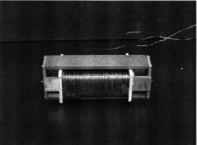
We have experimented a variety coil design with a square cross section.
of VCA designs. Figure 3.1 shows a moving
-Figure 3.1 Early prototype of radial field, square cross-section voice coil
The stator, consisting of NdFeB permanent magnets is constructed such that there is a uniform magnetic flux oriented from the inside (axis) of the actuator to the outside. It is a 2-dimensional approximation of a radial magnetic field. This design has the feature that strains of significantly greater than 50% can be achieved, but at correspondingly lower pressures than other designs would afford. Figure 3.2 shows a sectional view of a possible embodiment of a radially magnetized voice coil design. The white arrows represent the magnetic flux lines.
Radially Magnetized Tube with Iron Core
Figure 3.2
High Permeability shell
Coil
Air Gap
Solid model of radial voice coil.
A radially magnetized tube with an iron core, concentric with an iron shell establishes a
magnetic field across the air gap. A major advantage to radial designs is the uniformity of the field strength achievable along the length of the actuator. The cost, however, is that it is difficult to radially magnetize permanent magnet materials, making them expensive, and causing their field strengths to be typically 10-20% lower than axially magnetized magnets of the same material. Figure 3.3 shows an axially magnetized design, where, similarly to the radial design, the magnetic flux runs along the axis of the magnetic core, into the iron shell at one end of the actuator, and then back across the airgap to the core, to complete the magnetic circuit. The white arrows represent the magnetic flux lines.
Coil
High Permeobility shell
dAolli Mognetized Cylinder
Figure 3.3 Solid model of axial voice coil.
The major difference between axial and radial designs is the uniformity of the flux in the air gap, along the length of the actuator. While radial designs achieve relatively uniform field strengths, axial designs tend to concentrate the flux near the open end of the air gap. Just as an axially magnetized permanent magnet behaves in air, the radial component of the flux is concentrated at the ends, not along the length, of the magnet. The axially magnetized, moving coil VCA in figure 3.3 is a typical design and is commercially
available.
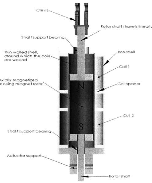
We have chosen a moving-magnet design, as opposed to moving coil design for the VCAs to be used in the arm. While a moving-magnet design can result in a slightly greater moving mass (this, of course, is not always the case and depends on the coil mass
and whether the VCA is being designed for high force or high speed operation), it affords a simpler construction geometry enabling smaller, more streamlined actuators. A
S hof t support bearing
Potor shaft t Rvels linecriv)
Ihin walled shell, ton shell
around which the coils are wound
-Coil I
AExiAy magnelized
rn oving magne t fotor . Cod sp=cei
Shof t st.1ppott brarton
Acfuaoo support~
Figure 3.4 Sectional view of the moving-magnet, axial VCA used in the wrist
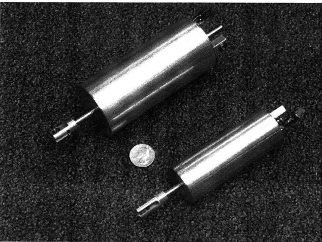
The stator consists of two independently wound coils inside a thin iron shell. The rotor is a cylindrical, axially magnetized NdFeB permanent magnet, with shafts extending from each pole, supported at the ends in linear bearings. The lengths of the rotor and the coils are designed such that throughout the range of motion of the actuator, one coil remains in the magnetic field of the south pole of the rotor; the other coil, the north. The current in each of the two coils is in opposite directions, matching the opposing polarities of the magnetic fields at either end of the rotor. The strokes of the bicep and wrist actuators are 4.7 cm and 2.5 cm, respectively. Figure 3.5 shows the finished bicep and forearm
Figure 3.5 Bicep and forearm voice coil actuators
3.2 SPECIFCA TONS
End effector forces of 20 N were desired on the arm, which correspond to peak actuator forces of approximately 100 N and 50 N for the bicep and forearm actuators, respectively. Table 3.1 shows the parameters for each actuator design, based on
assumptions of an average air gap field strength of 0.25 T, and magnetic field perpendicular to the actuator coils.
Table 3.1 ACTUATOR PARAMETERS
Desired Peak Average Average Coil Number
Peak Force Current (I) Field Diameter (d) of Coils
(F) Strength (B) (n)
Forearm 50N 3A 0.25T 0.0287m 840
The permanent magnets used in both the forearm and bicep VCAs are axially magnetized NdFeB (grade N40) rods with surface field strengths of approximately 1.25 T. The most significant unknown in the above table is the average air gap field strength. The flux behavior across the air gap is difficult to measure or model. Consequently, empirical data was collected (tests were done on a BEI voice coil), and conservative estimates were made for the expected average field strength. Given the large degree of uncertainty in this and other estimates, the table above incorporates a safety factor of 2 in terms of peak actuator force.
We have built and tested a variation on this voice coil design (see figure. 3.6). By effectively stacking smaller VCAs within one, and connecting their outputs to a common rotor such that their forces sum in parallel, the limit on peak actuator pressure effectively vanishes. Practical design considerations would of course limit the pressures achievable, but the force produced in the actuator will grow linearly with length, while the diameter stays constant. This of course would make VCAs look more attractive with respect to the metric of peak pressure, once again making it difficult to characterize the actuators in a normalized way such that they can be compared fairly with other technologies. The technique of increasing length for higher force is relevant because it is often the case in designing human-form robots (with limbs having high length/diameter ratios) that adding width, or thickness to the actuators (limbs) is very costly, but longer actuators, as means to higher forces, can be accommodated. A 3-stage prototype of a VCA using this design has been built and has verified the possibility of increasing peak pressure in this manner, but was not used in the construction of the direct-drive arm presented in this thesis.
~Mcqgr& --xidly nicrelize~d
Figure 3.6 Solid model of parallel stacked voice coil actuator
3.2.2 COST
The VCAs constructed for this thesis use readily available materials. The internal components (the coil separators, the shell around which the coils are wound, the
endplates) are machined from aluminum; the shafts are standard hardened steel shafts, running in ceramic linear bearings. The outer shell is thin-walled steel tubing. The assembly of the VCAs is entirely by press fit. As a result, with the exception of some tight tolerance machining operations, the construction and assembly of VCAs is easy, cheap and fast. Because VCAs have fewer moving parts, and do not involve delicate mechanical components such as brushes and commutators, their cost, complexity and manufacture times are lower than those of DC motors. As a result of the simplicity of their design, they are also more robust to operating conditions than DC motors.
3.2.3 EFFICiENCY
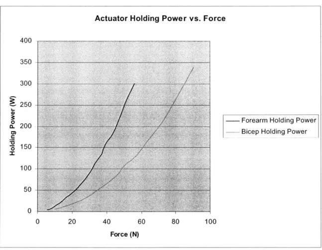
A major shortcoming of VCAs is their inefficiency at low speeds. Their low
backdriveability necessitates that they consume significant amounts of power, even while not moving. This problem can be alleviated to some extent by using springs and
carefully choosing the geometry of a robot so as to minimize constant loads, such as gravitational forces. Robot design with voice coil actuators should therefore take
inspiration from the way human bodies are designed. Relaxed states should involve low torques by ensuring that joints settle in local equilibria (stable equilibria, in the case of a relaxed shoulder or elbow, or unstable equilibria as in the case of a locked knee in a low-energy standing position). Figure 3.7 shows the measured zero-velocity power
consumption by the forearm and bicep actuators, as functions of holding torque.
Actuator Holding Power vs. Force
400
350 300
250
- Forearm Holding Power a. 200
- Bicep Holding Power
150 100 50 0 0 20 40 60 80 100 Force (N)
Figure 3.7 Measured zero-velocity holding power for the voice coil actuators
For small, non-mobile robots with low payload capacities, and whose main goals are smooth, friendly interactions with humans, the tradeoff between efficiency and quality of motion is acceptable.
CHAPTER 4. ARM DESIGN
4.1 MECHANICAL DESiGN
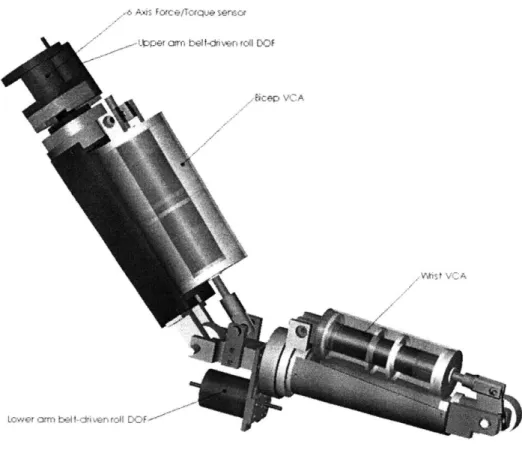
e, A, Forc e/Torque sersor
pper cm arc, bet ieni jr DCO
-bceg VCA
Figure 4.1 Solid model of 4 degree of freedom direct-drive arm
Figure 4.1 is a solid model of the 4DOF direct-drive robotic arm we have built. VCAs drive the bicep and forearm degrees of freedom, while brushed DC motors are driving the upper and lower arm roll degrees of freedom. The roll degrees of freedom are necessary to give the arm enough dexterity to execute meaningful trajectories. The geometry of the arm is modeled after a human, with a forearm slightly longer than the upper arm. The end effector is currently a small knob. This is useful for developing and
evaluating the VCA mechanical and control systems, but in the future, hands with tactile feedback may be implemented. The range of motion of the arm is comparable to that of a
DOF--human. The elbow and wrist have approximate ranges of motion (ROM) of 90', while each of the roll degrees of freedom has an ROM of approximately 2000. Table 4.1 summarizes the properties of the arm.
Table 4.1 ARM DESIGN PARAMETERS
Peak End Effector Forces 20N
Peak Acceleration (hand) 2g
Peak Acceleration (forearm) ig
Joint Ranges of Upper arm roll 2000
Motion Lower arm roll 2000
Bicep 90*
Wrist 900
Dimensions Upper arm 0.20m
(lengths) Forearm 0.1 7m
Hand 0.08m
The arm is constructed mainly of aluminum. The arm segments (or bone structure) are sections of thin-walled aluminum tubing, to maximize stiffness and minimize weight. All rotational axes use preloaded ball bearings, to ensure that the structure of the arm does not compromise the smooth, muscle-like performance of the actuators. The bearings minimize noise, backlash, and friction. Figure 4.2 shows the method of using a set screw to spread the arms of the actuator clevis to apply an adjustable preload to the clevis bearings.
The upper arm roll and elbow degrees of freedom have preload springs to help offset the gravitational torques due to the mass of the lower arm segments. The springs are not necessary, but they improve the arm's performance, give it a more natural resting position, and minimize the risk of sudden collisions when the power to the arm is turned off. The elbow springs are shown in figure 4.3.
Figure 4.3 Photo of elbow joint springs
4.2 ACTUA TION AND FEEDBACK
The bicep and wrist degrees of freedom are driven by VCAs, and the angular positions of the two joints are obtained via Hall Effect rotary position sensors (Honeywell HRS 100). The VCAs attach to the arm segments upon which they act (forearm and hand) at a distance from the joint that is approximately 115th the length of that segment.
End effector forces are therefore approximately 115th of actuator forces. The upper and
lower arm roll degrees of freedom are driven by Maxon Motors brushed DC motors. The motors act on the roll segments of each arm via a 8:1 belt reduction. The reduction allows for a moderate increase in torque, while maintaining a very high degree of backdriveability, and minimizing problems associated with gearboxes. The belts
introduce no backlash, and they have some inherent damping that helps in the control of the joint positions. Joint position and velocity information for the two roll degrees of freedom are obtained via Maxon MR encoders on the backs of the roll motors.
For future control system development on the arm, there is a 6 axis force/torque sensor in series with the upper arm, that will be used to measure inertial forces, as well as gravitational forces (for future implementation of trajectory, force, impedance, or hybrid control schemes). Local force sensors (closer to the end-effector) could be used to form force-control loops around contact and payload forces. A potential future development for VCAs is to include integrated position, velocity, and force sensors in the actuators themselves.
4.3 ELECTRICAL AND CONTROL HARDWARE
The control system development for the arm was done on an IBM workstation, using the DSP-based DSPACE prototyping hardware and software. The DSPACE
software interfaces with Matlab's Simulink program, and the hardware interfaces with the sensors and actuators via a 8 channel ADC and a 8 channel DAC. All control system software was developed and implemented using Matlab and Simulink. The amplifiers used to drive the roll motors and the wrist VCA (the less powerful of the two VCAs) are Maxon Motors linear amplifiers with peak current outputs of 2 Amps. The elbow VCA is driven by a higher power Maxon Motors pulse width modulation-based controller with a peak current output of 10 Amps. The opposing pairs of coils in each VCA are driven by the same control signal, in opposite directions. Figure 4.4 shows the motor driver setup, consisting of linear amplifiers, digital amplifier, and Dspace
I/O
board, used to drive the arm.Finally, a photograph of the finished arm can be seen in figure 4.5.
CHAPTER 5. KINEMATICS AND DYNAMICS
5.1 KINEMA TiCS
Figure 5.1 is a schematic of the 4 DOF arm. The 4 angles that describe the state of the arm are denoted by 6h, 0e, Of, and 0,.
O6
and Of are the upper and lower roll angles, respectively. Their axes are aligned with the axes of their respective arm segments. Angles Oe and Ow are the angles of the VCA-actuated degrees of freedom, the elbow and the wrist.
Ob (upper arm roll)
Ge (elbow angle)
ef (forearm arm roll) w (wrist angle)
Figure 5.1 Schematic of kinematic arm structure
In the interest of conserving control bandwidth, all trajectory control tests were executed in joint space, eliminating the need for real time computation of large jacobian matrices. Conventional techniques for computing the inverse kinematics of a 4 DOF arm exist, but were not necessary to effectively evaluate the performance of the VCAs, the arm, and the controls systems developed.
With regard to the implementation of workspace-coordinate control systems (based on the end effector positions, solved using forward and inverse kinematics), it is important to note that the 4DOF arm is underconstrained with respect to the position of the end effector alone, necessitating a sophisticated control algorithm that introduces constraints between the different degrees of freedom, or imposes constraints on the orientation (in addition to the position) of the end effector. For example, such a
constraint may attempt to keep the bicep joint angle as close to zero as possible, since it is the most costly to move in terms of power consumption.
5.2 DYNAMiCS
The goal of implementing a model-based controller is to use knowledge of the system parameters to give the controller feedforward information that will enable better tracking performance for pre-scripted trajectories. Contrary to a gain scheduled
controller, a full dynamic model provides a priori estimates of control inputs that account for position-dependant system parameters, desired state variables (and their time
derivatives), and prescribed trajectories (and their time derivatives). For the development of such a model-based controller, simple PID controllers were used on the 2 roll degrees of freedom and the elbow, maintaining constant (zero) angles at those joints. This
effectively reduces the 4DOF arm to a 1 DOF planar arm, for the purpose of focusing very closely on the model and performance evaluation of the VCAs themselves. A full
dynamic model was created for the 1 DOF arm. The dynamic model takes into account inertial forces, viscous damping, gravitational forces, actuator winding resistance and inductance, position-dependant actuator attachment radius, and a position dependant actuator constant, accounting for the non-linearities within the VCA. The dynamic model for the VCA driving a IDOF arm is:
ii = [I/(Kmi Ri)]*[Ii 6i+MigljCos6g + KbI]; (2)
Where Kmi is the position-dependant VCA actuator constant, Ri is the position-dependant actuator attachment radius, Ii is the arm moment of inertia, O, is the angular acceleration of the joint, M is the mass of the arm, 1,i is the distance to the centroid of the arm, ,gi is
the gravitational angle of the joint (measured from horizontal), Ki is the viscous damping constant for the joint, 6, is the angular velocity of the joint, and ii is the current input to the VCA, which obeys the following first-order dynamics:
V,=Liji+Reii; (3)
Where V is the control input (voltage) to the actuator, and Li and Rei are the coil
inductance and resistance, respectively. The following sections explain each of the terms in the above dynamic equations.
5.2.1 ACTUATOR CONSTANTS
Ki is the VCA motor constant. Its units are N/Amp. Since the permanent magnet rotor
travels within the coils, the interaction between the induced and permanent magnetic fields varies in strength, creating a position-dependant actuator constant. Effectively, the actuator constant can be regarded as:
K,,i = le1 * B (4)
From (1), where 1c, and Bi are coil length and position-dependent magnetic field, respectively. This non-linearity has been measured for each actuator, and the profile of the position-dependent actuator constant, which is characteristic of both the bicep and wrist actuators, is shown in figure (5.2).
Wrist VCA Force vs. Position
8 7 6 z 0 U. 4 2 1 -0
Wrist VCA Force
0 0.005 0.01 0.015 0.02 0.025 0.03
Wrist VCA Position (m)
Figure 5.2 Plot of position dependancy of wrist actuator constant
i
For simplification, the relationship between actuator constant and joint angular position has been linearized as follows:
For O, ; Oimd :
K,= [(Kia Km i min/ Oimid] Oi +Kmin ; (
For 0. > 0.d:
K, = [-(Kimax -Kimin)/ Oid]*Oi +(Kimin +2(Kimax- Kimin)); (
Where Kimax and Kimin are the maximum and minimum actuator constants, ?hnid is the
middle of the range of motion of joint i, and ?i is the angle of joint i. For these calculations, Kimax, Kimi and ?hnid were measured empirically, for the best accuracy. This linearization describes an actuator profile as follows:
Linearized Wrist Actuator Constant vs. Position
8 7 6 5 4 3 2 1 0
-+- Linearized Wrist Actuator Constant
I IIIIi
0 0.005 0.01 0.015 0.02 0.025 0.03 Wrist VCA position (m)
Figure 5.3 Linearization of position dependancy of wrist actuator constant
5) 6) 0 0 (U U (U U) ---i
'V
5.2.2 EFFECTIVE ACTUATOR ATTACHMENT RADIUS
Ri is the distance from the point of attachment of the actuator clevis to the axis of rotation
of joint i, measured perpendicular to the axis of actuator i. It is the distance R, in figure
5.4.
Figure 5.4 Schematic of position dependency of actuator attachment radius
Ri is clearly position-dependant, and it varies according to:
R
i = laiCos(-r
-, - ,) ;22 (7)
Where each of the parameters lai, 6;, and 8
ai is defined in figure 5.4. For the calculation
of Ri, the axis of the actuator is assumed to be parallel to the arm segment to which it is attached. In reality, this angle varies by less than 5'.
5.2.3 INERTIAL AND GRAVITATIONAL EFFECTS
The first 2 terms in equation (2) represent the torques due to the inertia of the arm, and gravity. These are the dominant effects in the in the dynamic model for the arm. The gravitational term helps to minimize steady state position error, and the inertial term significantly improves tracking performance by adjusting the control signal based on desired acceleration in place of desired position alone.
5.2.4 VIsCousDAMPING
The model includes a small amount of viscous damping. The primary source for velocity-dependant damping is eddy current damping within the actuators, although small amounts of viscous damping are present due to friction in the rotary encoders, and the viscosity of the oil used on the actuator shafts.
5.2.5 ELECTRICAL DYNAMIC MODEL
A simple first-order model was used to represent the actuator coil electrical
dynamics. Equation (3) shows this model, where Li and Rei are the measured coil inductance and resistance of the respective actuators. Given the large size of the actuators, and the small size of the arm segment, the electrical time constant of the actuator coils is significant, necessitating these terms in the dynamic model.
The resultant system model is third order, with voltages to the actuators as the control inputs, and angular positions of the joints (and their first and second derivatives) as state variables.
CHAPTER 6. CONTROL SYSTEM DESIGN
6.1 OVERVIEW
Three control systems were implemented on the arm, in attempts to explore the potential of VCAs as robotic actuators, and to exploit their best characteristics. The first control system developed is a basic PID controller with full state feedback. The PID controller was implemented on all 4 degrees of freedom, and basic trajectory tracking tasks were executed in joint space. The second control system developed is a PID controller with gain scheduling that varies the control gains to account for some of the dominant non-linearities in the actuators themselves, as well as in the construction of the arm. The gain-scheduled PID controller was implemented on all 4 degrees of freedom, and once again trajectory tracking tasks were executed in joint space. Third, a more sophisticated model-based controller was implemented on an individual VCA-driven joint, with dynamic model-based feedforward compensation in addition to PD feedback.
A full dynamic model was created for one of the VCAs (the wrist actuator), in an attempt
to characterize it well enough to improve controller performance. As a means of
exclusively testing the dynamic model of the VCA itself, the model-based controller was only implemented on one degree of freedom, however, it can be extended to multiple degrees of freedom using conventional techniques [6].
6.2 PID CONTROL SYSTEM
The first control system implemented on the arm was a simple PID controller, implemented on all 4 degrees of freedom. No system model was used, and all non-linearities were ignored. Feedback gains were determined empirically, since parameters that were difficult to characterize determine the stability of the system.
4 DEGREE OF FREEDOM PID CONTROLLER
OUTPUT SIGNALS TO DC (ROLL) MOTOR CONTROLLERS
OSITIONNELOCITY SENSOR SIGNALS
DAC
E :t:-forearm roll positon Ini C E14DCC
Eno delta position A -1 In2 0Oft forearm roll control signal
DS1 104ENCPOSCl forearm roll velocity
0 upper aim roll position 00t2 upper aim roll control signal DAC
DS1104ENCP C2 upper arm roil ol Upper and Lower Arm DSIIO4DAC_2
Rol PD Controler
ENCODER
MASTER SETUP
DS1 104ENCSETUP
Trjectory generator
OUTPUT SIGNALS TO VOICE COIL MOTOR CONTROLLERS
HALL EFFECT POSITION SENSOR SIGNALS
... wrist1ontolsig l S DAC
MU AC rst and elbow position -"P0fl
DS1 104MUJXADC Vkist and Ebow PID Controler DS11I 4DACC4
elbow control sga A
DS1104DACC3
Figure 6.1 Block diagram of PID controller for 4DOF arm
Where the block diagram for the individual PID controllers is:
WRIST PID CONTROLLER
WRIST PROPORTIONAL
POSITION CONTROL
I SIGNAL
n2t
WRISTPGAIN
>risne WRIST DESIRED CONTO From POSITION
OUTPUT TO
Integrator WRISTIGAIN Saturation ACITAO
DERIVATIVE
CONTROL
DWRIST VEl=LOCITY SIGNAL
in2 WRISTDOAIN
Figure 6.2 Block diagram of wrist PID controller ENCODERP