HAL Id: tel-00011519
https://tel.archives-ouvertes.fr/tel-00011519
Submitted on 1 Feb 2006HAL is a multi-disciplinary open access
archive for the deposit and dissemination of sci-entific research documents, whether they are pub-lished or not. The documents may come from teaching and research institutions in France or abroad, or from public or private research centers.
L’archive ouverte pluridisciplinaire HAL, est destinée au dépôt et à la diffusion de documents scientifiques de niveau recherche, publiés ou non, émanant des établissements d’enseignement et de recherche français ou étrangers, des laboratoires publics ou privés.
etching using specular and diffuse X-ray scattering
Luca Peverini
To cite this version:
Luca Peverini. Study of the processes of layer growth and ion beam etching using specular and diffuse X-ray scattering. Condensed Matter [cond-mat]. Université Joseph-Fourier - Grenoble I, 2005. English. �tel-00011519�
U.F.R. de Physique
THÈSE
pour obtenir le grade de
DOCTEUR DE L’UNIVERSITE JOSEPH FOURIER-GRENOBLE 1
Etude des procédés de croissance de couche et
de décapage ionique par mesures de diffusion
spéculaire et diffuse de rayons X
Présentée et soutenue publiquement le 25 février 2005 par
Luca PEVERINI
Discipline: Physique COMPOSITION DU JURY:
J. Chevrier Université Joseph Fourier Président
C. Boragno Università di Genova Rapporteur
P. Dhez Centre d’Orsay Rapporteur
E. Ziegler ESRF-Grenoble Directeur de thèse J. Lilensten Université Joseph Fourier Directeur de thèse
THESIS TITLE
Study of the processes of layer growth and ion beam
etching using specular and diffuse X-ray scattering
by Luca Peverini
A thesis submitted to the University Joseph Fourier Grenoble, 2005
Contents
Contents...iii
Acknowledgements ...1
Abstract... 3
Introduction... 4
Chapter 1 Hard X-ray optics ... 7
1.1 X-ray optics with grazing incidence mirror and multilayer reflectors ...8
1.1.1 Total reflection mirrors...8
1.1.2 The X-ray total external reflection phenomena... 11
1.1.3 Mirror coatings: thin films and multilayers... 12
1.1.4 Specifications for hard X-ray mirrors ... 18
1.2 Imaging reflective optics... 19
1.3 Focusing... 24
1.4 Kirkpatrick Baez optics... 27
1.4.1 Mirror manufacturing... 27
1.4.2 Layer coating... 30
1.5 Performance of X-ray reflective optics... 31
1.6 Future applications of SR reflective optics ... 31
Chapter 2 Surface roughness...33
2.1 Surface finish parameters... 33
2.2 Roughness characterization techniques... 34
2.2.1 Scanning probe techniques ... 36
2.2.2 X-ray based techniques ... 38
2.2.3 High resolution angular dispersive diffuse X-ray scattering ... 40
2.3 Thin film and multilayer characterization ... 44
2.4 The definition of Power Spectral Density... 45
2.4.3 2D and 1D power spectra ... 50
2.4.4 PSD models... 52
2.5 Scaling model ... 54
2.6 Linear stochastic model of growth/erosion of thin film ... 55
Chapter 3 X-ray Scattering theory ...58
3.1 X-ray reflectometry... 59
3.1.1 Coherence criteria in X-ray scattering ... 59
3.1.2 Specular reflection... 60
3.1.3 Diffuse X-ray scattering analysis of a rough surface ... 66
3.1.4 Diffuse X-ray scattering from a rough thin film ... 72
3.1.5 Transition layer model ... 78
3.2 Time-resolved reflectometry... 80
3.3 Summary ... 85
Chapter 4 Experimental technique and instrumentation ...86
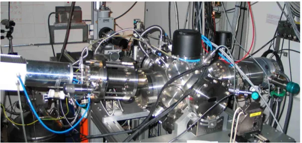
4.1 Beamline description ... 86
4.2 Apparatus: design strategy and realization ... 87
4.2.1 Sample environment, positioning and X-ray alignment... 90
4.2.2 Sample Holder ... 92
4.2.3 Sputter gun ... 94
4.2.4 Ion source... 96
4.2.5 Detection system... 98
4.3 Instrument control and data transfer ... 104
4.4 Temporal scans... 106
4.5 Data correction... 106
4.6 Experimental measurements and normalization ... 109
4.6.1 Specular reflectivity... 109
4.6.2 Diffuse scattering measurement ... 110
4.7 Instrument performance and application... 112
Chapter 5 Real-time studies on film growth ... 116
5.1 Substrate characterization... 116
5.2 Determination of film thickness and optical constants... 120
5.3 Real time analysis in the case of a thick film ... 124
5.4 Study of tungsten film growth on smooth silicon substrate ... 129
5.5 Roughness analysis: conformity during film growth... 136
5.6 Alternative approach to extract the PSD ... 147
5.7 Dynamic scaling analysis... 155
5.9 Minimization of the surface roughness ... 160
Chapter 6 Real time studies on surface etching ... 162
6.1 Ion beam sputtering processing ... 162
6.2 Ion-induced ripple formation ... 163
6.3 Ion erosion experiments ... 167
6.3.1 Evolution of roughness conformity during ion erosion... 172
6.3.2 TIS and roughness evolution during tungsten ion erosion ... 174
6.4 Ion beam assisted deposition... 182
6.5 Ion bombardment of silicon... 185
Conclusion and outlook... 189
Résumé... 193
Acknowledgements
I wish to thank Dr. Eric Ziegler for his constant help and valuable advice throughout this research and for being the initiator of this project. These were the most exciting years of my scientific career. I would also like to thank Prof. Jean Lilensten for supporting and encouraging me during the thesis.
I am honored that Professors Corrado Boragno and Pierre Dhez were willing to judge this work.
Special thanks go to Dr. Igor V. Kozhevnikov for his guidance and for being always willing to discuss and exchange new ideas as well as for his contribution during the analysis of the experimental data. The originality of his theoretical formalism constitutes a unique contribution to this work.
I would like to thank my colleagues Dr. Thierry Bigault and Dr. Joanna Hoszowska whose help and encouragement throughout the experiments, allowed me to obtain new and original experimental results. It was a very good experience to work with them.
I am grateful for assistance and help during the design and the preparation of the setup to Jean-Yves Massonnat, Robert Hustache, Gerard Rostaing, Cyril Ponchut, Marc Dubrulle, Jean-Christophe Peffen, Christine Borel, Philippe Villermet, Jean Pierre Vassalli, Laureant Claustre and Manuel Perez. I am indebted also with all the support groups of the ESRF for their effectiveness in performing any kind of practical work, hardware and software.
I wish to express my thanks to Amparo Rommeveaux from the Metrology Laboratory and Emilie Dubard from the Surface Science Laboratory of the ESRF.
I kindly acknowledge Dr. Christian Morawe and Dr. Andreas Freund for fruitful discussions.
I am thankful to Hélène Rocchiccioli and Manuel Sanchez del Rio for their contribution given to the realization of a very useful data analysis software for X-ray scattering data.
I am indebted with Dr. Gavin Fox for his help during the last moments of the manuscript preparation. He always proved a true friend in troubled times of my life during the last three years.
Many thanks to all those who have contributed to the realization of this works: Alessandro Mirone, Claudio Ferrero, Roberto Felici, Roberto Cerbino, Marco Potenza, Marzio Giglio, Anatoly Snigirev, Irina Snigireva, François de Bergevin, Peter Takacs, Giovanni Pareschi, Mauro Ghigo, Daniele Spiga, Alessandro Patelli, Timm Weitkamp, Bruno Golosio, Finn Christensen and David Windt.
Special thanks to Silvia, Laura, Annamaria, Quinto and in particular to Rosalia for their support, encouragement and immense patience over the course of my time spent at the ESRF.
Abstract
A novel X-ray scattering technique and a dedicated apparatus have been conceived and realized at the optics beamline BM5 at the ESRF. The apparatus permits to study the surface roughness in-situ and in-real time via grazing incidence X-ray scattering. The interaction of X-rays with the surface was analyzed in the framework of the first order scalar perturbation theory expressing the surface’s attributes through the power spectral density function. Information on the rms roughness, the correlation length, the roughness conformity and the scaling exponents characterizing the synthesis process could be extracted.
The potential of the method was demonstrated in two particular cases: thin film deposition by magnetron sputtering and surface etching by ion beam bombardment. Finally, the experimental results obtained were discussed in the light of the present models of film growth and ion interaction with solids.
Introduction
Any real surface is marked by the presence of roughness. On a macroscopic level the concept of surface roughness should be familiar to anyone. Most of the light we see is light scattered diffusely from rough surfaces. For instance, objects that are observed under conditions which differ from the specular one are visible. Roughness also induce friction, when one body moves relative to another body with which it is in contact, and this allows, for example, to have grip between shoes and the ground for walking.
A wide variety of surfaces and interface present in nature, possess the characteristic of roughness and can be associated with the fractal concept defined by Mandelbrot [1] in terms of fractional Brownian motion. Many surfaces appear as a self-affine instead of a pure fractal surface. This is often the case of surfaces that are of interest in technology, e.g., in X-ray optics, microelectronics or EUV lithography, when dealing with spatial scale ranging from several µm up to the atomic scale. The concept of self-affine surface has been created to describe a surface that is in-between that of a pure fractal, an object showing the same morphology at different observation scales, and a non-fractal object. In mathematical terms, this is an object that rescales anisotropically at different spatial coordinates (lateral and vertical).
Roughness is a measure of the topographic relief of a surface around a mean plane conventionally taken as zero level. For synthetic surfaces, roughness, and its stochastic nature, arises from the manufacturing process. These processes may involve deposition, grinding, polishing, and etching techniques. At the atomic scale the morphology of a surface is still rough. At this scale, roughness is caused by the action of a stochastic process while the surface morphology is governed by the interplay between several relaxation mechanisms: the dynamics of surface roughening due to the random arrival of particles and smoothing due to material transport induced by surface relaxation [2]. In the analysis of roughness and of the relaxation mechanism that generates it, the fractal concept is powerful because it enables to describe the morphology of a surface with a limited number of statistical parameters. For instance, when dealing with surface scatter
measurements: three statistical parameters are sufficient to describe both the surface topography and the distribution of the scattered radiation.
For any surface, the study of roughness presents both fundamental and practical interests. In the case of coated surfaces, from a fundamental point of view, roughness is related to the kinetics that controls film deposition and therefore studying the roughness evolution may bring insights on the growth mechanisms. Technologically, the study of roughness is important since roughness determines the ultimate performance of the reflective optical elements used, for example, in X-ray optics or EUV lithography.
This thesis is a contribution to the development of hard X-ray optics for synchrotron radiation sources. Almost any application of synchrotron radiation requires optical elements to condition the X-ray beam. The short wavelength in use and the source characteristics (flux exceeding 1013 ph/sec and beam divergence below few µrad) impose unprecedented specifications for the reflecting surfaces, which have to satisfy requirements on smoothness and figure finish at the atomic scale, to fully exploit the beam properties. Nowadays, there are three classes of reflective optics used in the conditioning of synchrotron radiation beams, namely grazing incidence mirrors, crystals and multilayers. To optimize the surfacing of these elements, a metrology with accuracy at the atomic spatial scale is needed. This is the primary motivation of this thesis. The objective of the project is to realize a real-time on-line roughness-measuring instrument for surfaces and thin films to be used in synchrotron radiation applications.
Presently, the techniques of investigation of roughness can be divided in two main categories: (i) Scanning Probe Techniques such as stylus profilometry, optical interferometry, Scanning Tunneling Microscopy and Atomic Force Microscopy. (ii) Scattering Techniques, energy and angular dispersive. As the sensitivity and accuracy of each technique are only satisfactory within limited lateral spatial bandwidth and vertical heights, the combination of several instruments and measurements is essential for a full description of the morphology of a surface. Among these techniques, X-ray reflectometry is widely accepted as a routine characterization for determining thin-film properties such as density, thickness and surface roughness. For these characteristics, X-ray reflectometry was chosen to provide a representative description of the surface analyzed during this work.
The experimental work achieved was performed at the bending magnet beamline BM05 at the European Synchrotron Radiation Facility.
Keeping in mind that the performance of a reflective-based imaging device is eventually related to the various imperfections of the mirrors surfaces, Chapter 1 will present an overview on the general manufacturing issues of the X-ray optics for synchrotron radiation sources. Several reflective optical elements commonly used in
manufacturing technologies currently employed. Layer coating, figuring, and polishing processes will be discussed and compared with more recent approaches. As the main tool of investigation of this thesis is the scattering of X-rays from surfaces, Chapters 2 and 3 will review the physical and mathematical concepts underlying the scattering phenomenon in the case of a single surface (substrate) and particularly when a film is grown on it. The main roughness parameters and the statistical tools commonly used to describe a surface are presented first. Those parameters are linked to the theory of scattering from a rough surface in Chapter 3 using the first order scalar Perturbation Theory. Emphasis will finally be given to the concept of time-resolved reflectometry showing the potential of the method in contrast to other "post-process" characterization techniques.
The main practical tasks were to design, implement and characterize an apparatus and a technique to perform time-resolved studies on thin films. These are extensively described in Chapter 4. Chapter 5 presents the most representative results obtained experimentally, thus demonstrating the performance of the instrument in terms of spatial and temporal sampling. The comparison of some of these measurements with results obtained with an atomic force microscope complements the findings. On the basis of the experimental observations, a more detailed description of the physics underlying the growth process will then be given. The experimental results are presented in the context of an eventual use of this method for manufacturing mirrors. Emphasis is given to the "real time" advantage of the method for surface roughness optimization. The other important part of this thesis concerns the study in situ of ion beam etching of thin films and of silicon substrates. This is discussed in Chapter 6. The intriguing formation of ripples observed during the experiments is also presented and discussed.
Chapter 1 Hard X-ray optics
Modern synchrotron radiation (SR) sources such as the Advanced Photon source (APS-USA), the European Synchrotron Radiation Facility (ESRF-France) and the Super Photon ring (SPring-8-Japan), deliver photon beams of unprecedented intensity and quality. The size of the source is of the order of a few tens of microns FWHM and the X-ray beam divergence is well below the milliradian. As an example, at the beamline ID01 of the ESRF, the beam divergence is of 0.208 x 0.009 mrad2 and the flux after monochromatization in the order of 1013 ph/sec. The available photon energy range for these machines spans from few tenths of kilo electron Volts (keV) to several hundreds of keV. The associated wavelength range is 100 Å - 0.1 Å.
Surfaces almost ideally figured and finished are needed to reflect efficiently X-rays between 0.1 keV and 100 keV through total external reflection from mirrors and Bragg reflection from multilayers (ML) and crystals. Unfortunately, the finite quality of real mirrors will partially spoil the exceptional brilliance of the available photon beam. Local deviations from the ideal reflecting surface, called figure slope errors, should be kept in the 1 µrad rms range over the whole mirror length (~1 meter) and micro roughness should be in the few Å rms range. As traditional mechanical polishing techniques have remarkably evolved over the last few years, these requirements can nowadays be achieved over a relatively wide range of materials. However, this is still a remarkable challenge, especially when a full exploitation of the partial coherence of the source is needed, e.g., in phase contrast imaging, X-ray fluctuation spectroscopy or X-ray interferometry applications.
The large variety of SR optical elements can be categorized in 4 families: crystal monochromators, grazing incidence mirror reflectors (focusing or not, with or without coating), compound refractive lenses and Fresnel zone plates. For all of them the surface imperfections give rise to diffuse scattering which degrade their optical performance. However, in this thesis only the reflective optics is presented. Additional information concerning the other optical components have been recently reviewed by Dhez (see [3]
1.1 X-ray optics with grazing incidence mirror and multilayer reflectors
1.1.1 Total reflection mirrors
Grazing incidence X-ray mirrors are nowadays widely used as energy low pass filters, focusing and imaging devices. Usually, the mirrors of a reflective optics are made of a super-polished light material substrate, such as Si, SiC or glass, coated with either a high-density (high-Z) metal, a few tens of nanometer thick, or with a multilayer (ML) coating. When coated with ML, reflective mirrors can be used as an energy band pass filter or as a low-resolution high-flux monochromator as compared to single crystals. Here, thanks to the small grazing angle, the thermal load per surface unit is reduced, as it is spread over a large area keeping a spectral purity ∆E/E in the order of few percent.
The grazing incidence mirror exploits the phenomenon of total external reflection (TER). As for any electromagnetic wave and material, the reflectivity of a photon beam shining onto a material increases as the grazing angle of incidence gets smaller. However, for sufficiently short wavelengths, typically less than a few nanometers, an abrupt increase in reflectivity, known as total external reflection, occurs when the grazing angle of incidence becomes smaller than a value known as the critical angle, see, e.g., Figure 1-1. This is because the refractive index of materials is slightly smaller than unity for short wavelengths. In other words, passing from air (n= 1) to the reflecting material (n < 1), it is possible to totally reflect the beam if the incident angle θ (angle between the surface of the sample and the incident beam) is small enough. This occurs when the incident angle is smaller than the critical angle θ given by the Snell/Descartes law, cr
cos(θcr)= n = − . Since n, in the X-ray domain, is very close to unity, this angle is 1 δ very small and a Taylor approximation in θ yields cr
2
cr
θ ≈ δ (1.1)
At the same time the constant δ is related to the bulk density of the reflecting material according to the following equation:
0 2 2 at r f δ λ π = Ν (1.2).
The quantities in (1.2) are, r0 the classical electron radius, λ the wavelength of the
radiation in use, Nat the atomic density of the material and f is the atomic scattering factor.
Formula (1.2) suggests that the best candidate materials to achieve the widest reflection band pass in the X-ray are high-density materials, such as Pt, Au, Ir and W.
To understand the TER phenomenon1 in a simple way we can imagine the reflection phenomenon considering X-ray photons as particles and associate to the reflecting material a critical momentum perpendicular to the surface plane. The critical momentum can be written as qcr ~ n where e ne = N fat 1 is the effective electronic density. Particles with a perpendicular projection of the momentum higher than this critical momentum will penetrate while others will be reflected. Notice that the defined momentum does not explicitly depend on the photon energy. However, as the optical constant (and in turns n) depends on the X-ray energy, θcr is expected to change as well. A
practical equation can be written to relate the value of the critical angle of TER and X-ray energy in use:
[ ] cr[deg] ~ 4.4 deg
E keV ×θ ⋅keV ⋅ (1.3)
Eq. 1.3 is valid in the absence of absorption edges and for high-Z materials.
As the penetration depth is small in TER condition, the mirror reflectivity can be further tailored by coating a bare substrate of density ρsub with a material with a different
density, ρlayer. Let us limit ourselves to the case of ρlayer > ρsub. In this case the critical
angle is increased by a factor ρlayer/ρsub . This is a consequence of the relation that
exists between density and critical angle. Figure 1-2 shows the reflectivity curve of a silicon mirror coated with three different materials and assuming ideally smooth interfaces. As one can see, the critical angle of TER can be further increased by a factor 2-3 if the coating is done with a high-density material. The reflectivity is less than 100% because of absorption, which is greater for high-Z materials. To account for it, one must describe the film using a complex refractive index. Due to the finite thickness of the coating layer, interference effects may be present. These effects appear as oscillations on the reflectivity curve above the TER region and are called Kiessig fringes, after the name of the scientist who first discovered and explained this effect [4].
Let us discuss the reflectivity of a tungsten mirror at different energies (Figure 1-1) and grazing angle of incidence (Figure 1-2) of an X-ray beam. As one can see, to achieve an efficient reflection (TER) over a wide energy range one needs to reduce dramatically the angle of incidence. In this region the mirror behaves as a low pass filter.
From the above consideration, one can understand why normal incidence mirrors cannot be used in the X-ray domain as efficiently as in the visible light region: the region
1 This effect can be understood with the analogy with the launch of a stone onto the surface of a lake: the stone will only bounce at the water surface if the momentum projection is short enough, i.e., if the stone is thrown at
of angles and energy where reflection occurs efficiently is indeed limited to grazing angle only2. 0.8 0.6 0.4 0.2 0.0 R ef le cti vi ty 100 80 60 40 20 0 Energy [keV] θinc= 0.125° θinc= 0.25° θinc= 0.5° θinc= 1° W [50 nm] /Si
Figure 1-1: Reflectivity of a tungsten-coated silicon mirror at different glancing angles of incidence.
1.0 0.8 0.6 0.4 0.2 0.0 Re fle ct iv ity 0.8 0.6 0.4 0.2 0.0
Grazing angle [deg]
Absorption
Si
Cu, thickness = 20 nm Pt, thickness = 20 nm
Figure 1-2: Reflectivity versus angle of a silicon substrate coated with materials of different density, namely Si, Cu and Pt. The curves are calculated using a radiation wavelength of 0.1 nm.
2 Strictly speaking, using mirrors coated with short period ML, the use of normal incidence is technologically possible and can effectively used up to about 200 eV. This conditions are typical in EUV lithography.
1.1.2 The X-ray total external reflection phenomena
The first X-ray experiment on TER from flat and smooth surfaces was reported by Compton in 1923 [5]. The TER phenomenon was only discovered about 30 years after the discovery of the X-rays (Roentgen). His discovery has been one of the most important scientific events of this century as it opened up many new areas of modern science. Within a few years, this discovery was awarded the Nobel Prize, a clear confirmation of its importance.
It was found that the beam could be reflected by the surfaces of a polished glass and of silver inclined by angles of several minutes of arc at ~8 keV (Cu-Kα ). By studying the spectrum of the reflected beam, the critical glancing angle was found to be approximately proportional to the wavelength (see Eq. (1.3)).
Figure 1-3: The apparatus used by Compton for studying the total reflection of X-rays (taken from his Nobel lecture3).
For X-rays whose wavelength is one half of an Ångström, the critical glancing angle from crown glass was found to be about 4.5 minutes of arc (0.075 deg), implying a reflective index differing from unity by less than one part in a million. The experimental difficulties encountered before the Compton discovery were due to the fact that the polarizability δ for common materials at X-ray wavelengths is extremely small, typically 10-5÷10-6, thus generating deviations from the direction of the incoming beam that were very small and difficult to be recorded with the equipment available at that time.
Furthermore, for X-rays, the refractive index of a material n is slightly less than unity. This means that concave rather than convex lenses and very large radius of curvature would have to be used for an X-ray beam to converge. Recently [6], this possibility was proved technologically realizable by stacking behind each other several concave lenses in linear array of a low-Z material to form a compound refractive lens (CRL).
1.1.3 Mirror coatings: thin films and multilayers
In SR radiation optics mirrors are frequently coated with the materials that help matching the requirements of a specific application, e.g., in terms of reflection within a given range of angles or energy. As previously stated, the most common way to achieve efficient reflection at grazing incidence is to use, either mirrors coated with a high-Z material, e.g., Ir, Pt or Au, or multilayer-coated mirrors.
Total external reflection can provide usable grazing angles up to a few tens of keV (see Figure 1-1). However, above this energy range total external reflection would occur at very small angles and long mirrors would be needed to allow a usable acceptance. This
would lead to tighter constrains in terms mirror alignment and handling. An interesting solution was pioneered by Spiller in the seventies for extreme ultraviolet region (EUV)[7]. He understood first that, by layering two materials with dissimilar densities, a spacer made of a low-Z material and a high-Z as a “reflector”, it was possible to fabricate a 2d crystal-like structure capable of diffracting an X-ray beam with an excellent efficiency. Since then, metallic multilayers have been successfully employed for a variety of applications from the EUV to the hard X-ray range, where substitute solutions are rare.
As first explained by Spiller [7], the use of synthetic multilayers instead of a single layer can finally lead to the largest angles of incidence accessible with a synthetic structure. Here, the reflection occurs due to the Bragg reflection phenomenon, i.e., the waves partially reflected at each interface add in phase when constructive interferences occur.
The reflectivity curves for three material systems, namely a Si substrate, a Si coated with a W layer and a periodic ML, are shown for illustration in Figure 1-4, at a grazing angle θinc=0.25°. The curves show that, by stacking together two materials with dissimilar
densities, one can access regions where the reflectivity for a single material would be negligibly small. Figure 1-5 shows the dependence of the reflectivity on the number of layers present in the stack. The ML structure is the same in the three cases. The saturation occurs for different number of bi-layers due to the variation of the absorption with the X-ray energy. As one would expect, absorption becomes less effective when the radiation energy increase.
As shown in Figure 1.4 the reflectivity is sharply peaked around angles fulfilling the Bragg condition as for perfect crystals. The reflectivity of a ML can be further tailored through an a-periodic design of the stack. With such a variation of the periods along the stack the ML can be employed as a wide band reflector in the angle or the energy ranges.
1.0 0.8 0.6 0.4 0.2 0.0 Re fle ct iv ity 100 80 60 40 20 0 Energy [keV] Silicon Substrate Layer coating, 50 nm Periodic multilayer [W/Si]1000 hW=hSi=1.5 nm
Figure 1-4: Reflectivity versus energy for grazing incidence mirrors for different systems: Si substrate, substrate coated with Pt, 50 nm thick and with a periodic W/Si multilayer. The curves are simulated assuming smooth interfaces. The multilayer comprises 500 bi-layers with thicknesses τSi=1nm and τW =1nm. 1.0 0.8 0.6 0.4 0.2 0.0 B ragg P e ak R ef lec tiv ity 500 400 300 200 100 0 Bilayer Number E = 8.5 keV E = 17 keV E = 34 keV
Figure 1-5: Variation of the reflectivity of a multilayer as the number of bi-layer is varied along the stack at three different energies.
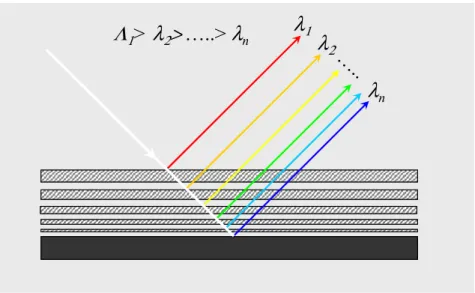
The general principle of these structures can be easily understood by discussing the reflection in the energy domain. This is schematically shown in Figure 1-6: if a white beam is illuminating such a mirror shorter wavelengths will penetrate deeper into the structure while others will be reflected by the upper layers. If the bi-layer periodicity is varied continuously, the Bragg law will be fulfilled locally along the stack with the results that many Bragg peaks will overlap over the energy range and result in wide band-pass reflection.
λ
1λ
2λ
n…
..
Λ
1>
λ
2>
…..>
λ
nλ
1λ
2λ
n…
..
Λ
1>
λ
2>
…..>
λ
nFigure 1-6: Principle of production of a broadband reflection using a multilayer with variable d-spacing. A white X-ray beam is partially reflected at the various interfaces.
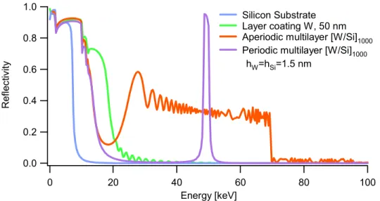
Figure 1-7 shows the reflectivity versus energy of several layered materials systems. Two of them are multilayer mirrors with a different layer distribution along the stack and assuming ideally smooth surfaces. The sharp Bragg peak corresponds to a periodic multilayer with constant spacing while the wide peak represents the spectral response of an aperiodic ML. The latter case corresponds to the combination [Si/W] with N=1000 periods for which the thickness of each bi-layer period is varied according to the following power law:
( ) ( )c a z i b i = + (1.4)
To obtain a wide reflection band the Si layer thickness was varied using the following parameters a=42.18, b=0.24 and c=0.25 which lead to a variation of the thickness from 4.0 nm to 0.75 nm. The W layer was varied using a=42.19, b=1.11 and c=0.25, i.e., varied from 3.50 to 0.75 nm. Notice that the oscillations are nothing but the effect induced by a smooth variation of the film thickness along the stack. It has been shown that[8], with local random variations of film thickness modulated by the function defined in Eq. (1.4), these oscillation can be reduced. These multilayer structures are now becoming popular in SR applications because of the large flexibility in contrast to the use of traditional crystals and mirrors.
1.0 0.8 0.6 0.4 0.2 0.0 R efl ec tivi ty 100 80 60 40 20 0 Energy [keV] Silicon Substrate Layer coating W, 50 nm Aperiodic multilayer [W/Si]1000 Periodic multilayer [W/Si]1000 hW=hSi=1.5 nm
Figure 1-7: Reflectivity versus energy for grazing incidence mirror coated with different materials systems. The aperiodic multilayer structure was calculated using the “a b c“ model parameters which are in given in the text and a grazing angle θi=0.25°.
The design of a multilayer can be done for the reflection to occur within well-defined spectral range and shape of the reflectivity curve. Moreover, ML can be routinely grown on any kind of shaped substrate, using techniques such as sputtering, evaporation and ion beam assisted depositions. However, the fabrication of short periods ML and the mastering of more complex structures such as aperiodic ML, requires the availability of a dedicated metrology capable of accuracy at the picometer spatial scale. The testing method should be fast enough to allow a short deposition-testing loop to improve the performance of the coating. These were the two important requirements that motivated the work carried out during this thesis: the development of an X-ray scattering technique and the realization of an apparatus for real-time on-line roughness measurements on surfaces and thin films.
The ultimate efficiency of a reflecting ML mirror is eventually determined by the absorption of the spacer material and by the surface errors (figure and finish). The former is minimized by employing low-Z materials. The latter requires highly specialized technological procedures to polish the surface at the desired level (see section 1.4).
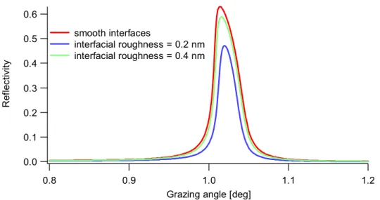
The effect of interfacial roughness on the ML mirror reflectivity is illustrated in Figure 1-8. The figure shows the reflectivity of a ML coating for different interfacial roughness values, 0 nm, 0.2 nm and 0.4 nm. The effect of roughness is much pronounced at larger angles, up to one order of magnitude when the roughness is varied from 0.2 nm to 0.4 nm. This example shows once more the importance of reducing roughness when high mirror acceptance, and in turn, flux or throughput are needed.
10-9 10-7 10-5 10-3 10-1 R efl ec tiv ity 3.5 3.0 2.5 2.0 1.5 1.0 0.5 0.0
Grazing angle [deg] Reflectivity Model: Nevot-Croce
smooth interfaces
interfacial roughness = 0.2 nm interfacial roughness = 0.4 nm
Figure 1-8: Reflectivity of a multilayer mirror [W(1.5)/Si(1.5)] versus grazing angle for three different interfacial roughness values.
The advances in film thickness measurements are generally important in the advanced technological processes implicated in the fabrication of layered devices. When fabricating ML mirrors, the individual layer thickness must be tailored for the boundaries to be close to the correct positions. The positioning of the absorber material (high-Z) should be in correspondence with the nodes of the wave field produced by superposition of incident and reflected field and spacer material (low-Z) in the remaining space. For the required exact period thickness control, a sputtering rate monitor with a sensitivity better than 0.001 nm is usually needed (1 pm). This sensitivity is not readily available by any commercial methods applicable for sputtering. Several techniques can be used as an in situ thickness monitor. The quartz microbalance is probably the most widely used since it is rather cheap and easy to use in comparison with the others. This is a resonance-frequency method that is based on the property of quartz, i.e., on the change in the resonance frequency with the change of mass. In principle, the thickness measurements performed with a quartz microbalance require knowledge of the film density and viscoelastic properties. The latter depend on the material and crystal structure or molecular arrangement in the film. The major drawback of this method is its sensitivity to thermal drift which may occur during deposition and can provide relative errors up to 20 %.
In-situ tracking ellipsometry, is an optical method based on the measure of the changes in
polarization of a monochromatic light , usually in the visible range, reflected from matter. The changes are related to the film thickness, the angle of incidence, the wavelength and the optical constants through an optical model of the film (accounting for film inhomogeneities, film structure and roughness). Therefore, the suitability of the method for a specific case depends on the validity of the model used. In-situ reflectivity is a method
1.1.4 Specifications for hard X-ray mirrors
Current (third-generation) SR sources deliver photon beams with high brilliance and moderate coherence. Full exploitation of coherence and brilliance preservation have required the use of grazing-incidence mirrors typically 1 m long or more, with surface figure errors below 3 µrad rms and surface micro-roughness errors less than 0.3 nm rms. These requirements, along with others concerning high heat loading and ultra-high vacuum-compatibility materials, have imposed stringent specifications for the mirror manufacturing process. Successful collaborations between synchrotron radiation beamline scientists and mirror vendors have resulted in the production of mirrors with a quality that is sufficient to meet the challenges of third-generation beamlines. Special fabrication tools were created, in particular, the long trace profiler (LTP) [9]. They were developed to measure surface figure and curvature of long aspheres. Standard commercial instruments were adapted to evaluate the figure and finish of these large optics.
The impressive improvement of micro roughness and slope error of mirrors used at ESRF over the last 10 years is shown in Figure 1-9[10]. The best achieved values at present settle at 0.07 nm and 0.15 - 0.17 µrad, for mirrors with a perfect area with a length of 160 mm and 400 mm, respectively. Typical figure errors obtained currently on SR mirrors are of the order of 2 µrad or less, depending on the mirror material, size and
Figure 1-9 Improvement of micro roughness and slope error of mirrors used at ESRF over the last 10 years. The best-achieved and measured values settle at rms values of 0.07 nm and 0.15 -0.17microrad, respectively, measured over a length of a perfect mirror area of 160 mm and 400mm.
Despite the remarkable results achieved technologically, the production of a high quality figured mirror remains a challenge. Only two techniques, namely differential deposition[11] and Elastic Emission Machining [12], are presently being developed for figuring and polishing elliptical mirrors to x-ray quality surface roughness. In these cases, only few test models have been produced and alternative solutions are still wanted. These optical devices are of interest for imaging applications and when X-ray focusing is needed. These issues shall be discussed in the next two sections.
1.2 Imaging reflective optics
When using grazing incidence mirrors, two reflecting surfaces are at least necessary to produce an extended image without residual aberrations. One can understand that by considering an ellipsoidal reflector. In this case, one can only focus a point source. Notice that this is not the case for an extended source. This is because the magnification of an image changes along the surface of the ellipsoid. The rays reflected closest to the source are demagnified while the ones reflected closest to the focus are magnified. For a reflecting surface working at grazing incidence the magnification changes linearly with the position, and only a short section should be used. This situation does not occur in normal
incidence optics for which the magnification changes only slightly. In geometrical optics the requirements for constant magnification can be expressed by the Abbe sine condition:
sin( ) constant sin( ) u y y u ′ = = ′ (1.5)
where u and u’ are the aperture angles of rays on the side of the object and image, and y’/y is the magnification. This condition defines for each optical system the shape of the effective surface as the intersection between the input ray and its corresponding output ray.
There are three different configurations for objectives, which are potentially suitable for grazing incidence imaging systems. These are called (i) Kirkpatrick-Baez (KB) type (ii) Wolter types and (iii) focusing collimator or "Lobster-eye" systems. All these configurations can fulfill the previous conditions and generate a constant magnification.
Among them the KB system is the imaging device the first most used in SR applications. Kirkpatrick and Baez obtained the first two-dimensional images ever obtained in a laboratory with grazing incidence reflection[13]. At that time they used two Pt coated cylindrical mirrors to image simple objects with a resolution of 1-2 µm over a field of view (FOV) of about 10 µm. The KB systems used today utilize two successive reflections to focus a source in two dimensions. They combine two elliptically shaped mirrors rotated 90° from each other, and having a common focus at a distance F. A representation for such a system is given in Figure 1-10. The main concept is the following: sagittal rays, weakly focused by the first mirror, become the tangential rays for the second and vice versa.
The focusing properties of such a mirror are described by the Coddington equations, that is:
For tangential rays
( 0)
1 1 1 2
sin
t t t
p +q = f = R θ (1.6)
and for sagittal rays:
( 0) 1 1 1 2 sin s s s p q f R θ + = = (1.7)
where p is the source object distance, qt is the distance of the tangential line focus
from the mirror pole and Rt and Rs are the mirrors radii of curvature in the two
orthogonal directions (meridional and sagittal).
If the mirror is spherical (Rt = Rs), the two focal lengths differ by a very large
factor and the mirror is clearly a poor image-forming device. In 1929 [14] Jentzsch pointed out that a toroidal mirror having a sagittal radius Rs smaller than the meridional radius Rt by a factor θ2 would bring the two set of rays at the common focus. Therefore, the ideal shape for KB mirror, to reduce astigmatism, is the toroidal one [15]. If so, only two mirrors could be used to image an extended source. However, because of technological difficulties in manufacturing such a mirror, and because the focusing along the sagittal rays is very weak, the mirrors are often prepared flat along this direction, i.e., with Rs = ∞ . Here, an extended source could be imaged with minimum aberrations
only if two pairs of crossed mirrors are used (i.e. four reflections)[16]. In this case aspheric surfaces are needed to remove the coma aberration completely and to ensure a good image quality.
When ML mirrors are employed two additional constraints must be added to the design, which is dictated by the choice of the d-spacing of the multilayer (if periodic). The requirement to achieve a certain magnification M is given by the following relation:
1 1 2 2 1 1 1 R d s s M M R d u u = − − (1.8)
where d1 and d2 are the multilayer periods, u1 is the distance between the object and
the first mirror and s is the distance between mirrors centers. The ML periods should also fulfill the following relation for the Bragg angles θ1 and θ2:
( ) ( )
1 1 2 2
2 sind θ = 2 sind θ = nλ (1.9)
For extreme focusing, the Kirkpatrick-Baez has proven recently to give the best focusing results (~90 nm, ESRF). This result was obtained with a KB coated with a ML to filter the incoming white beam.
X-ray X-ray Focus Parabola Hyperbola X-ray X-ray Focus Parabola Hyperbola
Figure 1-11: Schematic principle of a Wolter type imaging system
Figure 1-12: Wolter type mirror proposed for the fourth-generation SR sources, external diameter φ~.01
m (left), the Free Electron Laser. Wolter I mirror shells for Chandra mission (NASA), φ~1 m
(center). Artistic impression of the ambitious project XEUS (ESA), the X-ray telescope having φ~10 m will be linked at 50 m with another detectors satellite with the helps of an auto-tracking system (yellow box).
Wolter types and Lobster eyes [17] have been often proposed for hard X-ray telescopes (HXRT) as they can easily achieve a large effective area. An interesting application of the Wolter geometry has been also proposed for SR application and for the next FEL source, at the Linac Coherent Ligth Source (LCLS)4. With a replication technology derived from the experience accumulated over many years in HXR astronomy, miniature Wolter type mirrors have been realized for SR application as focusing or collimator devices. The operating principle is the following: X-rays enter on one end, undergo a single reflection at the interior surface, and exit at the other end with a different direction of travel. The optics is composed of truncated paraboloidal or ellipsoidal shells of revolution depending whether they are used as collimator or as focusing devices. Other authors have proposed the use of Wolter type mirrors for
imaging purposes and, in particular, to image extended objects at SR sources[18]. In this case, as for the KB system, two reflections are needed to fulfill the Abbe sine condition.
These optical devices are made of layers with materials deposited onto a supersmooth mandrel[19, 20]. When the mandrel is separated from the mirror shell, for example by thermal dilatation, the innermost layer replicates the mandrel smoothness and serves as the reflecting surface. One of the advantages of using this type of optics is that their cylindrical geometry is adapted to sustain high heat load, as it will be the case for FEL source. Moreover, it can image extended sources without residual aberration. By nesting several confocal mirrors shells it is possible to obtain a largest effective area. This feature is fully exploited when designing an X-ray telescope whose scope is to collect extremely weak flux or to image an extended source such as rest of a Supernova. Their major drawback is that the slope errors induced by the replication process are often too large to be used as optics for advanced SR applications.
Typical optics systems fabricated have a length of approximately 10 cm, a large end diameter of 3-4 cm and a small end diameter of 2-3 cm. A photograph of a large-diameter mandrel and its associated replicated optic is shown in Figure 1-12 (left). On the same figure, similar Wolter type mirrors for HXR astronomy are shown for comparison purpose.
Note that, while the KB geometry was first introduced for X-ray telescopes, the Wolter type mirrors were first designed for microscopy purpose. The reverse finally occurred: KB systems are used in SR source as microscopes and Wolter type mirrors in HXRT!
The lobster-eye5 design was proposed by Angel in 1979 [17]. The optical geometry consists of a series of micro channels disposed over a plate slightly curved. A ray passing through these micro channels is then either reflected once or transmitted. Rays reflected will be focused in a way which is determined by the plate geometry while rays that pass straight through, will contribute to a diffuse background. The finite height of the tubes will also produce some defocusing in the image, while the angle subtended by each tube at the detector will limit the resolution of the system. Despite of these drawbacks, the great advantage of this design is an almost unlimited field of view. This makes it ideal for imaging and particularly as an all-sky ray monitoring device. However, to date, no X-ray telescopes have been built using lobster-eye optics, principally due to the difficulty in
constructing the reflective tubes. Improvements in multi-channel plate technology are expected to lead to a further advance of this technology6.
Figure 1-13: Lobster eye imaging system
1.3 Focusing
A very important application of mirrors in X-ray optics is in beam focusing[21]. For this purpose, the mirrors should have an ellipsoidal shape to fulfill the requirement for constant magnification along the beam footprint thus reducing residual aberration and the number photons spread off-axis. If the mirror is coated with a ML, the requirement for constant magnification is translated in a lateral thickness gradient x∆ to fulfill the Bragg law along the mirror length while an additional depth gradient z∆ is designed according to the required spectral bandwidth.
In the TER geometry the small angle value complicates the optical design, the main aberrations being astigmatism and field obliquity [22]. When using Bragg diffraction from multilayers, the reflected intensity at the peak is less than in the TER case. However, this loss is recovered by the increase of aperture (larger angles). Therefore, this geometry is very efficient for achieving high magnification (large f-number) and throughput.
Figure 1-14: Kirkpatrick Baez mirror system fabricated at ESRF[23].
Their use is typically involved when ones need: i) to increase the flux density at the sample position, ii) to obtain a demagnification of the source or iii) in projection imaging geometries.
The performance of a focusing system is typically given in terms of flux and gain in as compared to an equivalent slit geometry. The reflectivity of each individual mirror is also important: in double-reflection geometry the reflectivity of each individual mirror contributes in a multiplicative way. This is particularly important for mirror systems working out of the TER condition because the reflectivity is intrinsically lower than in the TER region.
Let us illustrate this discussion with a practical example: consider a double multilayer mirror [W/Si]200 with a 3-nm period and thickness ratio γ=0.5 whose reflectivity is shown in Figure 1-8. We assume the interfacial roughness to be fully correlated and with a constant value of σrms= 0.2 nm throughout the stack. As seen in Figure 1-8, an increase of interfacial roughness by a factor 2, i.e., when passing from 0.2 nm to 0.4 nm, the reflectivity of a single mirror would decrease from 60% to 47 % and from 36% to 22% after two reflections.
At higher order Bragg peaks this reduction can reach several orders of magnitude. Therefore, to increase the Bragg angle, excluding an operation at the (higher) angles of the harmonics, the preferred solution would consist in reducing as much as possible the multilayer periodicity. Notice that, presently, the minimum usable ML periodicity is settled to about 1-2 nm [24]. The major limitations in fabricating smaller periods are
technological: presence of coating inhomogeneities, use of lateral gradients along the mirror, layer intermixing and difficulty of controlling/monitoring the film thicknesses.
An important figure of merit to evaluate the performance of a focusing device is the
gain factor G. It can be defined as the ratio between the flux at the focal point and the one
achievable with a slit that would lead to an equivalent spot size, that is
( ) ( ) ( ) 2 2 0 Focus sin slit eff slit R A RL G A M θ σ Φ = = = Φ (1.10)
where M=q/p is the mirror magnification, R the mirror reflectivity, L the mirror length, and σ the vertical source size assumed to be 80 µm. Let us consider different KB mirrors configurations, namely, an uncoated silicon system, and a device coated with two ML with dissimilar periods. We consider a typical distance from the source to the mirrors of p = 50 m and a focal length q = 1 m. The gains will be compared assuming mirrors 0.30 m long. The results in terms of G are summarized below. The former case leads to a grazing angle of the order of θ0=0.2 deg., and reflectivity R~1. These numbers provide a GAIN = 4 105. The gain is increased if we now consider a ML to increase the usable angles to some degrees. We consider first a ML W(1 nm)/Si(1 nm) such that the first Bragg peak is at θι~1 deg and another one with shorter periods, say a ML with W(.5 nm)/Si(.5 nm), for which the angle is increased by a factor 2. Their reflectivity, R=0.6 and R=0.5, respectively, leads to an increase of the gain of G= 2.5 106 and G= 2.4 107. If now we consider the last example and a focal length of 15 cm, which is possible to achieve with ML-coated KB we arrive to a gain of 109 (108 if we include .2 nm roughness when modeling the reflectivity), a remarkable result in contrast to a TER mirror: a factor 10000 more.
The roughness is probably the ultimate effect limiting ML devices. Its effect is illustrated by the example given in Figure 1-15 and Figure 1-16 showing the variation of the reflectivity at the first Bragg peak of a periodic ML with progressive roughness.
0.6 0.5 0.4 0.3 0.2 0.1 0.0 R efl ec tiv ity 1.2 1.1 1.0 0.9 0.8
Grazing angle [deg] smooth interfaces
interfacial roughness = 0.2 nm interfacial roughness = 0.4 nm
Figure 1-15: Reflectivity of the first Bragg order for different roughness values: 0, 0.2 nm and 0.4 nm.
0.5 0.4 0.3 0.2 0.1 Bragg peak r ef lec tiv ity 1.4 1.2 1.0 0.8 0.6 0.4 0.2 0.0 Interfacial roughness [nm]
Figure 1-16: Variation of the intensity at the first Bragg peak as a function of the interfacial roughness (Nevot Croce model).
As one can see in Figure 1-16, rms roughness values at each interface should be kept less than 0.3-0.4 nm if one wants to achieve a reflection above the 50% and therefore advantageous gain values.
1.4 Kirkpatrick Baez optics
1.4.1 Mirror manufacturing
Advances in mirror manufacturing have been recently made, and now it possible to fabricate x-ray mirrors with a few Ångstroms rms roughness and with sub-microradian
existing for polishing elliptical mirrors to x-ray quality surface roughness. The alternative to the fabrication of monolithic mirrors is to induce the desired shape by bending a flat mirror.
The techniques employed to reach the desired mirror shape are briefly summarized below:
Dynamical Shaping. Here, sophisticated bending techniques are used to shape an x-ray quality flat to an ellipse[21]. This method has successfully produced submicron x-ray beams, the best focus measured to date being 90 nm. However, the focus size is very sensitive to the bender adjustment and is complicated when compared to monolithic mirrors. Because of their additional complexity, benders become increasingly less attractive with stronger demagnification and decreased focal length (large f-number). On the other hand, a fixed shape is only optimized for a fixed energy, i.e., reducing the tenability performance.
Differential deposition. This recent approach allows to realize monolithic mirrors for elliptical K–B system [11]. With this approach, a high density Au layer is differentially deposited onto a cylindrical substrate to get the elliptical shape. Here the desired shape is obtained by mastering the reciprocal speed of the sample and/or sputtering target. This looks relatively easy, in comparison with other figuring techniques (see below). On the other hand the deposited thickness needs to be large, which typically results in the development of intrinsic roughness (columnar growth, crystallization).
Elastic emission machining. Several highly sophisticate techniques can presently be
used to reach a good figure up to the nm scale. Yamauchi et. used the fabrication methods of elastic emission machining (EEM) and plasma chemical vaporization machining (CVM) as ultra-precise figuring and polishing methods to prepare both flat and figured X-ray mirrors [12, 25]. EEM is a chemical machining method utilizing reactivity of the surfaces to ultrafine powder particles. Digitally-controlled EEM was proved to create atomically and crystallographically non-damaged surfaces with a figuring accuracy in the 0.1 nm r.m.s range. The main inconvenience of this technique is that the removal rate is low compared with other figuring techniques (ion-milling, diamond turning, etc). Plasma CVM, developed as a precise and effective preprocess of EEM, is a chemical-plasma process with an r.m.s. figure accuracy close to 1 nm, having a high removal rate comparable with conventional grinding. A combined process of plasma CVM and EEM in series was also proposed to enable the manufacturing of the ultra-precise X-ray optical components in a reasonable time. However, only a couple of test mirrors have been produced to date. Therefore, its implementation for intensive mirror production is far from being realized.
Ion milling and diamond turning. Two techniques are well known since the seventies for fabricating high quality mirrors: diamond turning [26, 27] and ion milling[28-30]. The former consists in making a mass replication master or in direct production, as in high precision aspherical optics. In such a case, a single diamond crystal cuts the surface of the metal or glass master into an arbitrary 3D surface with nanometer precision. A sub-nanometer position measurement system is thus required to control the motion of the diamond cutter. This technology was successfully employed for visible and infrared reflective optics because the residual surface roughness is extremely low compared to the wavelength in use. However, there are residual imperfections arising in this process: relevant periodic components appear at spatial scales determined by the removal rate of the tip in the order of several nanometers. This leads inevitably to an enhancement of the X-ray diffuse scattering, which in contrast is extremely sensitive to these spatial frequencies. As a results the diamond turning could only be employed in combination with a polishing technique adapted to polish curved surfaces.
In summary, in terms of gain and spatial resolution, a monolithic system seems to be preferable. Moreover, higher grazing angles can be accessed by coating the mirror with a ML. At large grazing angles dynamical shaping is not suitable due to mechanical constrains. Larger grazing angles would lead to larger beam acceptance, and in turn, to higher flux and lower residual aberrations, coma and field of obliquity. On the other hand, dynamical shaping guarantees a certain flexibility and the possibility of obtaining energy tunability [21]. Its use seems to be complementary and dictated mainly by the final application of the mirror optics.
Among the various solutions to obtain an elliptical mirror, the Optics group of the ESRF proposed first the dynamical shaping [21]. The dynamic shaping has been proved flexible and effective for its optical performance in term of focusing. To achieve X-ray focusing a bender shapes a flat mirror to an elliptical shape. The mirror can be made of a light-weight material as a silicon crystal substrate coated with a high-Z material or a multilayer coating to further tailor the X-ray reflectivity. Anyhow, a flat surface with atomic scale roughness has to be prepared. The details concerning the procedure adopted at ESRF can be found at the page reported below7. The best surface finish presently achieved is about 1Å (rms) while the best figure (flatness) for a thick specimen is around 1 µrad (rms).
1.4.2 Layer coating
Numerous materials can be deposited on substrates and various types of techniques of deposition have been used. The sputtering technique is probably the most widely used for coating metallic films.
The sputtering involves knocking an atom or molecule out of a target material by accelerated ions from an excited plasma and condensing it on a substrate either in its original or in a modified form. The sputtering can be achieved by a number of ways, including accelerating the plasma ions by a d.c. field, or with a d.c. field combined with a magnet (to direct the high velocity emitted electrons away from the substrate), with r. f. (with its self induced bias) as well as with ion beams. Hence, names such as magnetron or reactive r.f. sputtering reflect the process that has been used for the deposition.
The technique used in this study involves magnetron sputtering in an Ar+ plasma. This method has the reputation of providing good uniformity and sharp interfaces. Parameters known to influence the quality include sputtering pressure, pre-conditioning, film thickness and dc power. A detailed description of the system used in this dissertation is presented in Chapter 4.
There are many other ways to create complex layered structures. The traditional techniques are listed in the following items:
1. Evaporation –Thermal evaporation is the oldest technique, it involves vaporizing a
solid by heating the material to sufficiently high temperatures and recondensing it on a cooler substrate. The high temperature can be achieved by resistively heating or by an electron-beam hitting the boat containing the material to be evaporated.
2. Ion Beam Assisted Deposition (IBAD) – The interfacial roughness of film deposited by
e-beam evaporation can be further improved by making the film thicker and removing the exceeding material by ion bombardment or by parallel ion irradiation of an ion beam. These two processes are generally called IBAD. Here, smoothing occurring is though to be due to preferential removal of weaker bounded surface atoms.
3. Pulsed Laser Deposition – A pulsed infrared or ultraviolet laser beam is focused onto
a target material at a power density sufficient to vaporize it but not to form a hot plasma. Its main advantage in contrast to the previous methods is the possibility of choosing a wider range of materials, including, carbon, platinum, gold, tungsten, rhenium and tantalum.
Several authors have tested alternative deposition methods for microelectronic industry applications. However, they have not yet been used to produce ML synchrotron
optics. Examples of these techniques include, cluster deposition, atomic layer-by-layer growth, and ion beam deposition.
1.5 Performance of X-ray reflective optics
Although real surfaces have a continuous spectral range of error periods, the traditional way of specifying mirror quality is to divide their shape errors into two main groups: figure and finish. These two extreme regimes are distinguished only by their spatial wavelengths (or frequency). The figure errors are those left by the shaping process. They are generally in a spatial frequency scale range from 10 cm-1 down to the macroscopic scale of the mirror. They are measured by interferometry and are usually expressed in terms of Zernike polynomials. At smaller spatial scales, surface imperfections are called finish errors. Finish errors are imperfections left by the finishing process and cover the overall spatial-wavelength spectrum from the near-atomic dimension up to the macroscopic scale. However, as polished surfaces exhibit a fractal spectrum (or fractal-like), i.e., their power spectrum is a power law of the spatial frequency, their finish is only characterized below few hundred of µm (see chapter 2) and finally combined to figure measurements. All those errors can be described in terms of their power spectral density.
The light scattered from the surface irregularities degrades optical performance in several different ways. First, it reduces the optical throughput because some of the scattered radiation will not even reach the focal plane. Second, the wide-angle scatter will produce a veiling glare that reduces the image contrast or the signal-to-noise ratio at the detector. Finally, the intensity scattered at small angle will decrease resolution by producing an image blur.
A detailed description of these effects is beyond the scope of this work. Therefore, we will limit ourselves to mention two references, [9, 31], illustrating the way surface finish and figure errors affect the performance of an optical system. With the approach described in these works it is possible to describe the intensity in the image plane of an imaging optics in terms of the Power Spectral Density of the surface roughness. Eventually PSD measurements, available through surface metrology, can be used to predict the optical performance of X-ray optics.
1.6 Future applications of SR reflective optics
The two main tasks for future applications involved in the third and fourth generations of SR are: i) to preserve the high degree of spatial coherence and ii) to obtain extreme focusing down to the diffraction limit. For extreme focusing surface roughness and angular errors will have to be further decreased, depending on the specific
application. The development of fabrication processes controlled in-situ using SR itself is believed to achieve these two objectives.
Among the most promising applications envisaged for the near future, imaging techniques play an important role. They can be classified as full field or scanning. The full-field techniques include absorption radiography, tomography, phase-contrast tomography, phase contrast imaging. Depending on the level of resolution, the techniques use either direct illumination of the sample or additional magnifying optical elements (projection imaging). The diffractive optics promises to reach a resolution of 10 nm for 10 keV radiation, compared to the 90-100 nm limit at third generation synchrotron sources. Very promising is imaging for time-resolved studies of processes. Scanning methods, on the other hand, require focusing optics to provide a small beam cross section at the sample position and micro stages for mechanical movements of the sample.
There are wide prospects of combining scanning imaging techniques with other methods of X-ray analysis (chemical mapping, trace element mapping, magnetic diffraction). The full transverse coherence of the beam will allow the development of novel methods for the investigation of crystalline and non-crystalline matter. Many of these methods are already known from the domain explored by optical lasers, but the use of short-wavelength radiation in the Å regime will improve the resolution and expand the range of applications. Methods to be mentioned here are off-line holography, interferometry methods and speckle interferometry. Moreover, the use of coherent beams will enable the development of new techniques like lens-less imaging, where the information about the wavefront form and the intensity distribution provides phase information and allows the image of the object to be reconstructed with holographic methods.
However, even with the present advances in mirror fabrication technology, residual imperfections on mirrors (as well as on other optical X-ray SR components) will be found to degrade the quality of X-ray beams. This raises new challenges on mirror polishing and metrology and strongly motivates the subject of this dissertation.
Chapter 2 Surface roughness
As already pointed out, the finish of optical surfaces is an important issue in Hard X-ray optics because roughness leads to scattering thus leading to performance degradation of an imaging device. In this chapter, the main parameters affecting the surface finish are discussed by introducing the power spectral density (PSD) function. As mentioned previously, the optics performance can be expressed in terms of the parameters used to describe the PSD, i.e., the rms roughness, the correlation length and the roughness exponent.
In this chapter, the characterization techniques giving access to these finish parameters and the surface topography are presented in comparison with scattering methods and in relation to their spatial sensitivity. The scaling theory and the linear model of film growth are finally discussed. These approaches show that a parametric description of the roughness (through a physical model of the surface) combined with a scattering theory (see Chapter 3), enable one to make a detailed description of a surface morphology both in the spatial and temporal domains in a unique descriptive frame.
2.1 Surface finish parameters
The parameters describing the finish of a surface are usually defined from the surface Z(x,y) referenced to the zero mean surface plane. Let us consider for simplicity a 1D profile as schematically shown in Figure 2-1. The relevant statistical quantities about a surface topography can be defined in accordance to the following identity:
The root mean square (rms) roughness, σ: / 2 2 2 / 2 1 lim L ( ) L L L Z x dx σ →∞ − =
∫
(2.1)The rms profile slope, m:
( )
2 / 2 2 / 2 1 lim L L L dZ m dx L dx →∞ − =∫
(2.2)The rms profile curvature, c: 2 2 / 2 2 2 / 2 1 lim L L L d Z c dx L dx →∞ − =
∫
(2.3) 6 4 2 0 -2 -4 -6 Z( x) [n m] 800 600 400 200 0 x [nm] σ Correlation length L , ξFigure 2-1: Typical sampled profile, measured with an Atomic Force Microscope, after the flattening procedure (profile -line fit). The notation used in the text are illustrated on the profile.
The above definitions are written using the notion of infinite limits for the scanning length (or window) L. However, any real measurement can only be performed within a limited bandwidth. This leads to the well-known Nyquist theorem (also called sampling theorem). The theorem states that any real roughness measurement can be performed only in a discrete bandwidth of spatial frequency determined by:
min 1 max 21
f f
Nd d
= = (2.4)
where N is the number of sampled points and d is their sampling distance. The longest measurable wavelength is essentially the trace length and the shortest is twice the sampling interval, 2d , the reciprocal of the Nyquist frequency. For a profile roughness measurement, these limits arise from the fact that low frequencies are filtered out of the measured profile by the flattening procedure to remove tilt effects introduced by the measurement process, and high frequencies are removed by a mechanism involved in any realistic measurement, such as the finite lateral resolution.
2.2 Roughness characterization techniques
The various measurement techniques can be classified by the range of spatial wavelengths they can reach when measuring mirror imperfections. They can be divided in two main families: the ones measuring shape errors, generally based on optical

![Figure 1-8: Reflectivity of a multilayer mirror [W(1.5)/Si(1.5)] versus grazing angle for three different interfacial roughness values](https://thumb-eu.123doks.com/thumbv2/123doknet/15036453.690333/24.918.179.718.114.396/figure-reflectivity-multilayer-mirror-grazing-different-interfacial-roughness.webp)