Characterizing the Mechanical Properties of Drop Stitch Inflatable Structures
by
Lia DiGiovanna
Submitted to the
Department of Mechanical Engineering
in Partial Fulfillment of the Requirements for the Degree of Bachelor of Science in Mechanical Engineering
at the
M Massachusetts Institute of Technology
June 2013
ASSACHUSETTS INSll E OF TECHNOLOGY
JUL
3 1 2013
LIBRARIES
0 2013 Massachusetts Institute of Technology. All rights reserved.
Signature of Author:
Department of Mechanical Engineering May 10, 2013
Certified by:
Accepted by:
Anette Hosoi Professor of Mechanical Engineering Thesis Supervisor
Anette Hosoi Professor of Mechanical Engineering Undergraduate Officer
Characterizing the Mechanical Properties of
Drop Stitch Inflatable Structures
by
Lia DiGiovanna
Submitted to the Department of Mechanical Engineering on May 10, 2013 in Partial Fulfillment of the
Requirements for the Degree of
Bachelor of Science in Mechanical Engineering
ABSTRACT
This study investigates the mechanical properties of drop stitch inflatable structures with specific reference to inflatable stand up paddleboards. A sample of drop stitch material was fabricated and simple beam bending tests were performed at different pressures. This data was then used to invalidate a developed model for the deflection of the sample. High standard deviations indicate that the pressure inside the tested sample was changing throughout the duration of the tests. An
elastic modulus for the material was determined using the internal pressure. The results showed an elastic modulus on the order of 60 MPa. The fabrication process and results led to the conclusion that one of the main advantages of drop stitch technology is its ability to create unique shapes that are unable to be constructed with an inflatable alone. The results also showed that the beam becomes stiffer with an increase in internal pressure and that simple beam theory is
invalid for characterizing drop stitch inflatable structures.
Thesis Supervisor: Anette Hosoi
Abstract
This study investigates the mechanical properties of drop stitch inflatable structures with specific reference to inflatable stand up paddleboards. A sample of drop stitch material was fabricated and simple beam bending tests were performed at different pressures. This data was then used to invalidate a developed model for the deflection of the sample. High standard deviations indicate that the pressure inside the tested sample was changing throughout the duration of the tests. An elastic modulus for the material was determined using the internal pressure. The results showed an elastic modulus on the order of 60 MPa. The fabrication process and results led to the
conclusion that one of the main advantages of drop stitch technology is its ability to create unique shapes that are unable to be constructed with an inflatable alone. The results also showed that the beam becomes stiffer with an increase in internal pressure and that simple beam theory is invalid for characterizing drop stitch inflatable structures.
Acknowledgments
The author would like to acknowledge Professor Hosoi for her guidance and support throughout this process. In January, 2013 Professor Hosoi facilitated a trip to Maui, Hawaii on sports technology. This trip turned out to be one of the most rewarding experiences of my
undergraduate career and sparked my interest on the subject matter contained in this thesis. Professor Hosoi's kindness, enthusiasm, and expertise truly made my experience rewarding and enjoyable, and for that I cannot thank her enough.
Table of Contents Abstract... 3 Acknowledgments... 4 Table of Contents... 5 List of Figures... 6 List of Tables ... 6 1. Introduction... 7
2. Drop Stitch Technology 2.1 Drop Stitch Inflatable Design... 9
2.2 Manufacturing of Warp Knitted Spacer Fabrics... 10
2.3 Bending of Inflatable Beams... 12.
2.4 Relating Elastic Modulus to Pressure... 15
2.5 Buckling Analysis... 17
3. Test Procedure 3.1 Fabrication of Drop Stitch Inflatable Device... 19
3.2 Fabrication of Inflatable Device ... 23
3.3 Experimental Apparatus... 23
4. Results and Discussion 4.1 Results of Three Point Bending ... 26
4.2 Determining Elastic Modulus from Deflection Data ... 27
4.3 Determining Elastic Modulus from Pressure ... 30
5. Conclusions... 31
List of Figures
Figure 1: Photo of a standup paddle boarder ... 7
Figure 2: Components of drop stitch inflatable technology... 9
Figure 3: Construction of warp knitted spacer fabric ... 11
Figure 4: Machine that knits warp knitted spacer fabrics ... 11
Figure 5: Diagram of an inflatable structure in three point bending ... 12
Figure 6: Free body diagram of slice of drop stitch inflatable structure ... 13
Figure 7: Free Body Diagram of Area Directly Under Applied Force ... 15
Figure 8: Force Diagram of a Stand Up Paddle Boarder ... 17
Figure 9: Buckling Loads for average inflatable SUP ... 18
Figure 10: Side view of wooden apparatus and mounted fabric ... 20
Figure 11: Top view of sew ing process ... 20
Figure 12: Side view of stitched nylon ... 21
Figure 13: Fabricated drop stitch sample used for testing ... 22
Figure 14: Dimensions of fabricated sample used for testing ... 23
Figure 15: Texture analyzer and experimental apparatus ... 25
Figure 16: Close up of experimental apparatus ... 25
Figure 17: Raw data for two beam bending tests at 25psi and 30psi... 26
Figure 18: Simple model (Equation 13 and Table 3) vs. measured data (Table 2)... 29
Figure 19: Elastic Modulus as a Function of Internal Pressure... 30
List of Tables Table 1: Buckling Loads at Selected Pressures ... 19
Table 2: Results of beam bending tests... 27
Table 3: Average slopes from each raw data set... 27
Table 4: Values of elastic modulus (E) with the standard deviation (Y) for each model tested ... 28
1. Introduction
Inflatable structures are used in a variety of industries. They have automotive, spacecraft, military, and marine applications.' Distinct advantages include: lightweight design, efficient transport and deployment, flexible shapes and rigidity, and ability to return to its original shape after collapse. In the 1950's a new technology called drop stitch technology was explored to improve the performance of inflatable airplanes and small watercrafts. 2
This paper will look at drop stitch technology with specific reference to inflatable stand up paddle boards. Stand up paddle boarding is one of the fastest growing water sports,
combining surfing and kayaking and totaling a $7.2 billion industry.
Figure 1: Photo of a standup paddle boarder
1 Falls and Waters, "Bending Tests," 593.
2 Bagnell, "Recent Advancements," 807.
Stand up paddleboards have historically been made of foam and composites like regular
surfboards. A more recent advancement in the sport has been the use of drop stitch technology to create rigid, high performance, yet inflatable boards. These boards that can measure up to 11 feet in length simply roll up into a bag and are inflated at the usage site creating an easy and
enjoyable experience for the user. Understanding this technology further could facilitate the design of boards that are lighter, stronger, and more efficient.
Research on the subject of drop stitch technology is not extensive. Results of testing regular cylindrical inflatable structures are more accessible, and the benefits of drop stitch inflatables are fairly easy to come by. However information comparing the two and
characterizing the behavior of drop stich technology is minimal. Inflatable panels are often not characterized either because of the difficulty in forming an inflatable structure into a board or panel like shape. The background on these materials is further discussed in Section 2.
An experiment was done in an attempt to characterize the mechanical properties of drop stitch materials in order to predict its behavior and further understand the material. Due to the difficulty in obtaining pre made drop stitch materials, a small sample was fabricated to use for testing. This fabrication process is outlined in Section 3. Using this sample, three point beam bending tests were done at different pressures to measure the material's elasticity. It is predicted that a higher pressure will yield a higher elastic modulus. The results of the experiment are analyzed in Section 4.
2. Drop Stitch Technology
2.1 Drop Stitch Inflatable Design
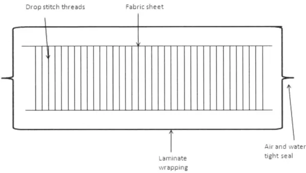
Drop stitch structures consist of three fabric, and an outer laminate as shown in
Drop stitch threads
basic components: drop stitch threads, connecting Figure 2. Fabric sheet
I
Laminate wrapping Air an tight s d water ealFigure 2: Components of drop stitch inflatable technology
The fabric is woven using a manufacturing process described in Section 2.2. During this process, a specified length of thread is left between the two fabric sheets. When the fabric sheets are pulled apart, they will remain parallel to each other at a distance equivalent to the specified
length of thread. This distance can range from 2 inches to 30 inches, and usually is constant. Certain manufacturing processes allow for a linearly varying thickness. 4 Thread density can
make a difference in both the stiffness and shape of the structure. A common thread density is
4 Bagnell, "Recent Advancements," 807.
50 threads per square inch. The threads and fabric are usually made of Nylon. The threads are what allow these inflatable structures to take unique shapes while still maintaining rigidity. Simple inflatables will not take the shape of a panel on its own.
Once the fabric is constructed it is wrapped in a laminate layer. This layer needs to be air and water tight and able to bond to the nylon fabric to facilitate the separation of the drop stitch layers once inflated. The materials used for this include neoprene, PVC, Kevlar, or more generally a non-permeable elastomer.5 When this is applied to stand up paddleboards in
industry, additional layers of material will be wrapped around the outside. As shown by Naish, in standup paddleboards these can be UV protection layers, chemical protection layers, etc. 6
2.2 Manufacturing of Warp Knitted Spacer Fabrics
Drop stitch technology is applied on a much smaller scale for use in fabrics, seat cushions, sports apparel, geotextiles and more. However instead of leaving inches of material between the two fabric skins, it is only on the order of millimeters or less.7 The side view can be seen in
Figure 3, and shows the identical structure to the technology used in standup paddleboards. The construction is the same and therefore the manufacturing process should be similar. Information on the manufacturing of large drop stitch materials is not readily available, so this section will briefly discuss the knitting process of these smaller fabrics often referred to as "warp knitted
Bagnell, "Recent Advancements," 808. 6 "Boards: Nalu Air 11 '0."
spacer fabrics." Top Layer Connecting Layer Bottom Layer
Figure 3: Construction of warp knitted spacer fabric8
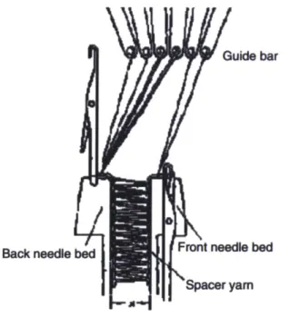
To produce these materials, the drop stitch threads and the fabric skins are completely stitched together. The fabric layers and the threads are made of the same material and knitted on a warp knitted machine. Figure 4 shows the machine with the threads.
Guide bar
Back needle bedFront needle bed Spacer yam
Figure 4: Machine that knits warp knitted spacer fabrics9
As shown above, the needle beds are spaced apart as the desired width of the fabric. For warp knitted spacer fabrics, this is millimeters or less. If drop stitch fabrics are made the same way, it can be assumed that these beds would be inches apart. In the case of a standup
paddleboard, it would be about six inches. These thinner fabrics also stitch the spacer fabrics at different angles, making them stronger. Instead of the threads running straight up and down, they criss cross into an "x" shape. This could be an area of interest for drop stitch inflatables.
2.3 Bending of Inflatable Beams
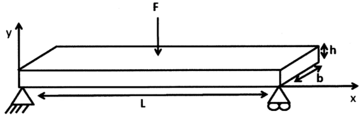
The following is a first attempt to develop the expected deflection of drop stitch inflatable structures. A simple three point bending will be considered as shown in Figure 5. To
approach this, a rectangular pressure vessel in bending was considered.
F
V
b
Figure 5: Diagram of an inflatable structure in three point bending
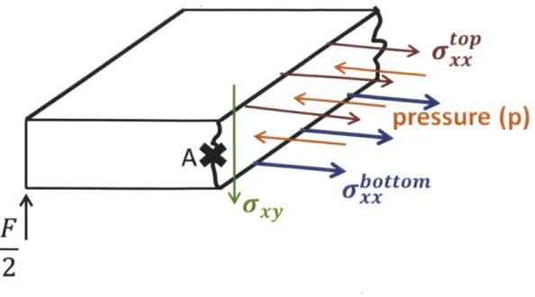
Taking a cut close to the origin, the forces on the slice are shown in Figure 6. These forces will be used to determine the internal stresses acting on the structure.
A
FT
top
xxpressure
(p)
L orUL LUt
cr
2
Figure 6: Free body diagram of slice of drop stitch inflatable structure
Using Figure 6 to create the equilibrium equations and solve for the three unknowns stresses it is found that: F= top bt + xbxOtom bt - pbh = 0 and ZMA = F+ x + o bt -2 2 x (2)
(
ot"bt = 0.
Solving for the stressesbottom = I Fx + ). (1) top 1 Fx 2 bth (3) (4)
The moment equation can be expressed as
M(x) =f h a, dA.
Assuming that the total stress is two time the stress on the top membrane is
M(x)= 2 p
the stress can be expressed as
where top =E Ey Uxx p (8) 1 d2V(X) p dx2 Rearranging d2 v(x) dx2 (9) pbh 2 2 -2 (Fx Eh 2bt 2
and using the boundary conditions
dv L\
0 and v(0) =0 dx \2
this produces the deflection equation at the midpoint where the testing will occur
v(x) = 2E1 _-b 2X 2 + pbh 2Lx - FL . 2Eft2bt' 3
p
)/ (5) (6) - o ttox h (7) (10) (11)Once the data is collected this deflection equation will be applied to find the elastic modulus at each pressure. Another model, the model for the deflection of a rectangular beam in three point bending, can be used to compare the results of the above model.
(L) FL
(12) 2 =48EI
2.4 Relating Elastic Modulus to Pressure
A second approach to develop the elastic modulus of drop stitch inflatable structures uses the
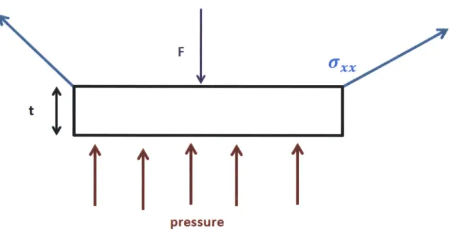
area being directly under the applied force, as shown in Figure 7. It can be said that a small piece of the membrane will relate the pressure and the effective elastic modulus.
F
1'
I I I I I
pressureFigure 7: Free Body Diagram of Area Directly Under Applied Force tI
Doing a force balance on Figure 7 yields the equation
-F + pLb - u,sin62bt. Using the constitutive equations relate stress and strain
Uxx = Emembrane Exx
L
L
and knowing that
is FL
3 (16)
4 8Eeff '
a final relation can be made for the effective elastic modulus
-1
E - 481 L2Emembrane(F-pLb) 12
eff ~ FL3 I 2b
where F will be the weight of the person on the board and I is the moment of inertia for a thin walled rectangle shown in Equation 18 as
I
=
(b3
+h
3) + (b + h)
6 (13) (14) (15) (17) (18)2.5 Buckling Analysis
An important aspect of the design of inflatable stand up paddleboards is the maximum load that can be attained with different internal pressures. Using similar concepts of the stresses shown in section 2.3 the pre tension stress and the bending stress in the top membrane can be added to find the buckling loads.
F paddler
F water
Figure 8: Force Diagram of a Stand Up Paddle Boarder
The pre tensioned stress plus the bending stress added together yield
ph My 6xx = 2t I
Buckling will occur when there is no longer any stress in the top membrane denoting the moment as
(19)
M = Fbuckle * L
8
and y as the distance from the neutral axis which is h/2. Rearranging, the buckling load can be related to internal pressure
81
Fbuckle - -p
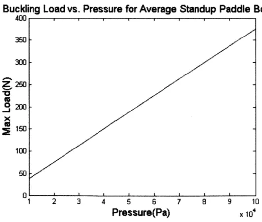
Using standard measurements for an inflatable stand up paddle board Figure 9 is obtained.
Buckling
400 10% z 0 -J x 350 300 250 200 150 100 50 0Load vs. Pressure for Average Standup Paddle Board
1 2 3 4 5 6 7 8 9 10
Pressure(Pa)
x 104Figure 9: Buckling Loads for average inflatable SUP
(20)
(21)
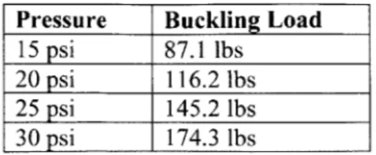
Table I shows some example pressures and the buckling load associated with it.
Table 1: Buckling Loads at Selected Pressures
Pressure Buckling Load
15 psi 87.1 lbs
20 psi 116.2 lbs
25 psi 145.2 lbs
30 psi 174.3 lbs
Since this calculation does not account for the drop stitches within the inflatable or the extra coatings previously discussed, it is expected that the buckling loads are slightly low. With the drop stitches and the coatings, these boards actually allow for riders up to 240 lbs. The buckling load was not tested because of the small size of the sample. However, the buckling load is still an important design parameter to consider.
3. Test Procedure
3.1 Fabrication of Drop Stitch Inflatable Device
In order to characterize drop stitch materials, a small sample was made to be tested. The size was determined based on feasibility and the scaling down of the dimensions of standard stand up paddle boards about 12 times.
The same materials were used for the following attempts at constructing a small scale drop stitch inflatable. The thread used was an abrasion resistant nylon thread measuring 0.21mm in diameter. The nylon fabric was rip stop nylon 0.08mm thick. The wrapping material was a PVC fabric sheet used for inflatable pool floats, making it water and air tight. Heavy duty PVC cement was used for all gluing purposes.
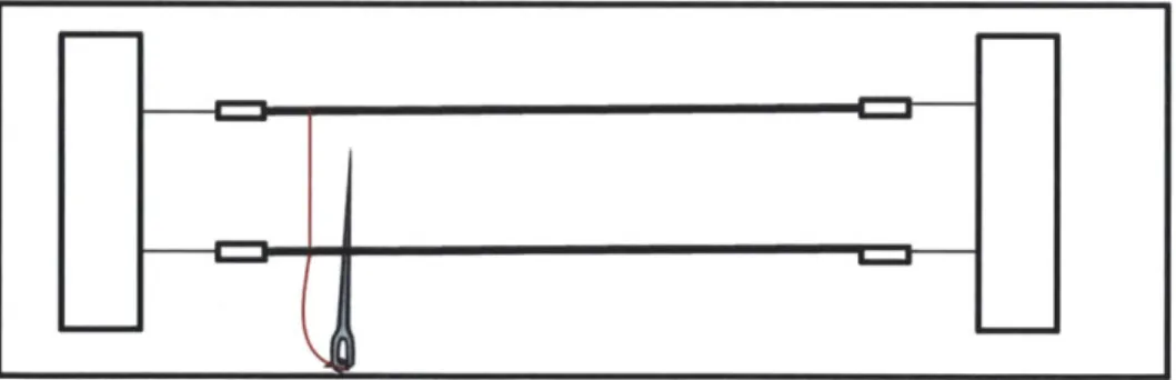
Although the materials changed, the way the drop stitch threading occurred remained consistent throughout the process. The fabric pieces were mounted to a wooden apparatus and placed 0.5 inch apart, as shown in Figure 10. Using a standard sewing needle, the needle would penetrate through both layers, leaving that 0.5 inch of thread in between the fabric pieces, since the pieces were pulled taught onto the wooden apparatus, as shown in Figure 11. The individual approaches are described below.
___ * 1.1
Figure 10: Side view of wooden apparatus and mounted fabric
Figure 11: Top view of sewing process
The first approach to create a small scale drop stitch inflatable device consisted of using the rip stop nylon as the interior fabric and wrapping it in the PVC fabric. The rip stop nylon pieces were sewn together and the device was removed from the apparatus. PVC cement was
F1
--placed on the outside edge of the nylon fabric, and it was placed onto the PVC fabric. This was repeated to the other side. All open ends were sealed and a valve was placed on a far end of the device. Upon inflating the device, the drop stitch part of the device did not expand properly. The PVC fabric inflated however the nylon fabric did not become rigid with it. In an attempt to bond the nylon to the PVC fabric, PVC cement was placed on the entire face of the nylon fabric, instead of just the edges. This resulted in the threads being constricted and a poor bond between the nylon and the PVC fabric. A side view of the stitched nylon is shown in Figure 12.
Figure 12: Side view of stitched nylon
The second approach used the PVC fabric to sew together as well as wrap. No rip stop nylon was used for this approach. The PVC fabric was sewn together with the nylon thread. It was then removed from the apparatus and PVC cement was placed sporadically on the face of the sewn PVC fabric. The device was wrapped completely and a valve installed. Upon inflation, the device did not inflate uniformly. However the areas where the sewn PVC fabric and the wrapping bonded correctly, traces of possible rigidity could be seen.
The third approach also sewed the thread into the PVC fabric. However instead of removing the device from the apparatus and then wrapping, the device was wrapped while still connected to the frame. This ensured the proper spacing of the threads and eliminated the potential of the threads being constricted by the gluing. The PVC cement was applied to the entire face of the sewn part and then pressed together and wrapped completely. Leakage was a
large problem in this final iteration. The most effective method was wrapping the stitched
portion twice and applying a heavy weight to the edges immediately following the application of glue. A small one way valve was installed at one end of the sample. PVC fabric was wrapped around the base of the valve and glued to avoid leakage. Figure 13 shows the final sample and Figure 14 shows its dimensions and components. The thickness of the wrapping material is 0.3mm.
Figure 14: Dimensions of fabricated sample used for testing
3.2 Fabrication of Inflatable Device
A standard panel shaped inflatable device was fabricated to use as a base line for testing.
This was made in a similar fashion, wrapping PVC fabric around the drop stitch inflatable, adding a one way valve and gluing together. However when inflated, the structure would not hold a panel like shape an immediately went into a tube like shape. This would not provide a valid base line for testing. This can imply that in addition to the added rigidity, drop stitch technology is used primarily to hold shapes that cannot be obtained by inflatable structures alone.
3.3 Experimental Apparatus
A three point bending test was conducted to measure the elasticity of the material at different
the material simply deforms with the rate of the machine and does not provide different
resistances. This may be a result of the small size of the sample. At high pressures above 30psi, the stitched PCV material begins to break away from the wrapping PVC materials. This may be a result of a poor bond between the stitched material and the wrapping material in certain areas. This resulted in testing at an internal pressure of 25psi and 30psi. The parameters measured were
force and deflection.
The machine used for the tests was a TA.XT.plus Texture Analyzer. The force and height were calibrated and the parameters for the test were set. The sample was simply supported on two blocks with the probe hovering above the center of the sample, about 55mm from the
platform, just touching the top of the sample. The test sent the probe down at 2mm/sec for 30mm and measured the force required to move at this designated speed. It then returned to it starting position at 3mm/sec. The experimental apparatus is shown in Figure 15 and a close up of the sample in the apparatus in Figure 16.
Figure 15: Texture analyzer and experimental apparatus
4. Results and Discussion
4.1 Results of Three Point Bending
The beam bending tests resulted in a positive correlation between the stiffness of the material and the internal pressure. Figure 17 shows one trial for 25psi and one trial for 30psi.
30 25 10%
0
20-15 10F 5 01 -1Raw Data 25psi and 30psi
0 1 2 3 4
Force(N)
5 6 7 8
Figure 17: Raw data for two beam bending tests at 25psi and 30psi
The above raw data shows the linear elastic part of the curve that indicates the stiffness. The inverse of each data set is plotted and a line fit to the data. The slope of the fitted line is determined and the results are shown in Table 2 with 95% confidence.
25psi raw data
30psi raw data
--Table 2: Results of beam bending tests
Pressure(psi) Trial Slope (mm/N)
25 1 6.355 0.020 25 2 6.824 ±0.030 25 3 7.006 ±0.022 30 1 4.543 ±0.022 30 2 5.733 ± 0.015 30 3 3.822 ±0.025
The slopes and uncertainties are averaged in Table 3 below.
Table 3: Average slopes from each raw data set
Pressure (psi) Slope(mm/N)
25 6.723 ± 0.388
30 4.699 ±1.114
The structure tested at 30psi has a much higher uncertainty than the one tested at 25psi, however the average is lower which is consistent with the hypothesis. This indicates that at a higher pressure more force is required to deflect the center of the sample. The slopes in Table 3 will be compared to two theoretical models to determine the most accurate model.
4.2 Determining Elastic Modulus from Deflection Data
To experimentally find the effective elastic modulus of the material, equation 11 is revisited
1 Fx3 FL2X
V(x) =(3 - pbhzxz + pbhzLx - 4)
2Ehzbt 3 4
Equations 11 and 12 (developed model and simple beam bending model) were applied to three sets of data for each pressure at 600 points at the linear section in the middle of the curve. Table 4 shows the experimentally determined elastic moduli for both models.
Table 4: Values of elastic modulus (E) with the standard deviation (C) for each model tested
25psi (172382 Pa) 30psi (206842 Pa) Developed Model (Equation X) E = -20.1 MPa E = -28.7MPa
Simple beam bending model E = 3.2694 MPa E = 31.664 MPa
(Equation X) 7=0.2019 MPa Y = 3.9673 MPa
The negative elastic modulus shows that the developed model is incorrect. Although it matches an expected order of magnitude the model cannot be considered valid. The large standard deviations within the simple model data show that the elastic moduli and pressures were not constant during the testing. When the pressure is held constant, the elastic modulus is shown to decrease throughout the duration of the testing. The source of this is most likely small air leakages within the sample that developed as a result of inflating the sample to a high pressure. Leakage tests were done in water and although the sample passed, the air was probably released during the testing as a result of the extra force from the experiment. This would result in a decrease in pressure, and since the pressure change throughout the test was not measured, this presents as a continuous change in the elastic modulus during the data analysis.
The value of the elastic modulus cannot be fully determined from testing this fabricated sample. The test can however give an order of magnitude estimate and validate the accuracy of simple beam theory on inflatables. Plotting the measured average slopes shown in Table 3 versus the simple model using
L) =FL 3 = 48EI'
Simple Model vs. Measured Data
0.07 1 9 1 1 25psi model 0.06 -25psi measured 30psi model 0.05. 30psi measured C 0.04 -0 0.03-0.02 0.01 0 0 1 2 3 4 5 6 7 8 9 10Force(N)
Figure 18: Simple model (Equation 13 and Table 3) vs. measured data (Table 2)
The slopes were determined and the differences were recorded in Table 5.
Table 5: Slopes and error of above graphs
Simple 25psi Simple 30psi Measured (m/N) .006723 .004699 Theory (m/N) .0008632 .00008913
Percent Error 678% 5172%
The above results reaffirm the hypothesis that the simple model cannot be used to characterize inflatable devices. The simple model yielded an elastic modulus on the order of
3-31 MPa, which is comparable rubber. Foams and polymers are on the order of 1.0-10.0 MPa, and
4.3 Determining Elastic Modulus from Pressure
Revisiting Equation 17, the elastic modulus can be plotted as a function of pressure.
2 1.8 1.6 1.4 1.2 1 0.8 0.6 0.4 0.2 n
X 108 Elastic Modulus vs. Internal Pressure
- I I I
-0 0.5 1 1.5 2 2.5 3
Pressure(Pa)
3.5 4 4.5 5
x 106
Figure 19: Elastic Modulus as a Function of Internal Pressure
This shows that the elastic modulus for an inflatable at 30psi is 75 MPa, and the elastic modulus at 25psi is 63 MPa. This is an appropriate order of magnitude and verifies that this can be an accurate way to express the elastic modulus as a function of pressure.
.0-,
0
5. Conclusions
The results of the performed experiment agreed with the initial hypothesis that an increase in pressure will result in an increased elastic modulus. However due to the inability to inflate the fabricated sample to more than two pressures, the original data was unable to be used to calculate the elastic modulus fully. An additional relation needed to be developed to understand the elastic modulus as a function of pressure. This yielded an elastic modulus of 75 MPa for the structure inflated to 30 psi.
One of the major conclusions that can be drawn from this study is that one of the main advantages of drop stitch technology is its ability to hold shapes that simple inflatables cannot hold. With sealant and fabric alone, the simple inflatable was unable to hold the desired shape of a panel. Since the shape was not even similar to the fabricated structure, tests would have been invalid. Another major conclusion is that the extra wrapping layers have a significant impact on the rigidity of standup paddleboards. The drop stitch technology provides the initial strength and the shape of the board; however the wrapping layers will allow it to withstand greater forces. The wrapping layers will also protect the board against UV rays, and the natural wear of the product.
Future research on this subject would greatly benefit from improving the fabricated sample. Testing different sealants and using an appropriate amount of force to bond the wrapping to the fabric skin would prevent air from leaking and hold the pressure constant. Preventing the change in pressure should result in a constant elastic modulus. Also, creating a sample that can be tested at more than two pressures would allow for a comprehensive definition of the elastic modulus as a function of pressure.
6. Bibliography
Bagnell, Daniel G. "Recent Advancements of Inflatable Multi-Hull Boats Utilizing Drop-Stitch Fabric." American Society ofNaval Engineers (2011): 807-812.
Bruer, Shanna et al, "Three-Dimensionally Knit Spacer Fabrics: A Review of Production Techniques and Applications." Journal of Textile and Apparel, Technology and Management 4 (2005): 1-3 1.
Cavallaro, Paul V. "Technology & Mechanics Overview of Air-Inflated Fabric Structures." Naval Undersea Warfare Center (2006): 1-11.
Falls, Jaye and Jennifer K. Waters. "Bending Tests of Inflatable Dropstitch Panels." American Society of Naval Engineers (2011):593-600.
Helliker, Kevin. "Surf s Up: The Rise of Stand-up Paddle Boards." Wall Street Journal, July 20, 2010. Accessed April 30, 2013.
http://online.wsj.com/article/SB 10001424052748703720504575377023651849234.html. Naish International. "Boards: Nalu Air 11'0." Accessed April 16, 2013.
http://naishsurfing.com/Nalu%2OAir%20 11 .0/#tab-2.
Ye, Xiaohua et al, "Development of the Warp Knitted Spacer Fabrics for Cushion Applications." Journal ofIndustrial Textiles 37(2008):213-223.