impact on gravitational-wave searches
The MIT Faculty has made this article openly available. Please share
how this access benefits you. Your story matters.
Citation Aasi, J et al. “The Characterization of Virgo Data and Its Impact on Gravitational-Wave Searches.” Classical and Quantum Gravity 29,15 (June 2012): 155002 © 2012 IOP Publishing Ltd
As Published http://dx.doi.org/10.1088/0264-9381/29/15/155002
Publisher IOP Publishing
Version Author's final manuscript
Citable link https://hdl.handle.net/1721.1/121223
Terms of Use Creative Commons Attribution-Noncommercial-Share Alike
arXiv:1203.5613v2 [gr-qc] 18 Jun 2012
on gravitational-wave searches.
J. Aasi1, J. Abadie1, B. P. Abbott1, R. Abbott1, T. D. Abbott2,
M. Abernathy3 , T. Accadia4 , F. Acernese5ac, C. Adams6 , T. Adams7 , P. Addesso58 , R. Adhikari1 , C. Affeldt9,10, M. Agathos11a, K. Agatsuma12 , P. Ajith1 , B. Allen9,13,10,
A. Allocca14ac, E. Amador Ceron13
, D. Amariutei15 , S. B. Anderson1 , W. G. Anderson13 , K. Arai1 , M. C. Araya1 , S. Ast9,10, S. M. Aston6 , P. Astone16a, D. Atkinson17 ,
P. Aufmuth10,9, C. Aulbert9,10, B. E. Aylott18
, S. Babak19 , P. Baker20 , G. Ballardin21 , T. Ballinger55 , S. Ballmer22 , Y. Bao15 , J. C. B. Barayoga1 , D. Barker17 , F. Barone5ac,
B. Barr3, L. Barsotti23, M. Barsuglia24, M. A. Barton17,
I. Bartos25
, R. Bassiri3,26, M. Bastarrika3
, A. Basti14ab,
J. Batch17
, J. Bauchrowitz9,10, Th. S. Bauer11a, M. Bebronne4
, D. Beck26 , B. Behnke19 , M. Bejger27c, M.G. Beker11a, A. S. Bell3 , C. Bell3 , I. Belopolski25 , M. Benacquista28 , J. M. Berliner17 , A. Bertolini9,10, J. Betzwieser6 , N. Beveridge3 , P. T. Beyersdorf29 , T. Bhadbade26 , I. A. Bilenko30 , G. Billingsley1 , J. Birch6 , R. Biswas28 , M. Bitossi14a, M. A. Bizouard31a, E. Black1 , J. K. Blackburn1 , L. Blackburn32 , D. Blair33 , B. Bland17
, M. Blom11a, O. Bock9,10, T. P. Bodiya23
,
C. Bogan9,10, C. Bond18
, R. Bondarescu34
, F. Bondu35b,
L. Bonelli14ab, R. Bonnand36, R. Bork1, M. Born9,10,
V. Boschi14a, S. Bose37 , L. Bosi38a, B. Bouhou24 , S. Braccini14a, C. Bradaschia14a, P. R. Brady13 , V. B. Braginsky30 , M. Branchesi39ab, J. E. Brau40 , J. Breyer9,10, T. Briant41 , D. O. Bridges6
, A. Brillet35a, M. Brinkmann9,10, V. Brisson31a,
M. Britzger9,10, A. F. Brooks1 , D. A. Brown22 , T. Bulik27b, H. J. Bulten11ab, A. Buonanno42 , J. Burguet–Castell43 , D. Buskulic4 , C. Buy24 , R. L. Byer26 , L. Cadonati44 ,
G. Cagnoli28,36, E. Calloni5ab, J. B. Camp32
, P. Campsie3 , K. Cannon45 , B. Canuel21 , J. Cao46 , C. D. Capano42 , F. Carbognani21 , L. Carbone18 , S. Caride47 , S. Caudill48 ,
M. Cavagli`a49, F. Cavalier31a, R. Cavalieri21, G. Cella14a,
C. Cepeda1 , E. Cesarini39b, T. Chalermsongsak1 , P. Charlton50 , E. Chassande-Mottin24 , W. Chen46 , X. Chen33 , Y. Chen51 ,
A. Chincarini52 , A. Chiummo21 , H. S. Cho53 , J. Chow54 , N. Christensen55 , S. S. Y. Chua54 , C. T. Y. Chung56 , S. Chung33 , G. Ciani15 , F. Clara17 , D. E. Clark26 , J. A. Clark44 , J. H. Clayton13
, F. Cleva35a, E. Coccia57ab, P.-F. Cohadon41
,
C. N. Colacino14ab, A. Colla16ab, M. Colombini16b, A. Conte16ab,
R. Conte58
, D. Cook17
, T. R. Corbitt23
, M. Cordier29
,
N. Cornish20, A. Corsi1, C. A. Costa48,59, M. Coughlin55,
J.-P. Coulon35a, P. Couvares22 , D. M. Coward33 , M. Cowart6 , D. C. Coyne1 , J. D. E. Creighton13 , T. D. Creighton28 , A. M. Cruise18 , A. Cumming3 , L. Cunningham3 , E. Cuoco21 , R. M. Cutler18
, K. Dahl9,10, M. Damjanic9,10, S. L. Danilishin33
,
S. D’Antonio57a, K. Danzmann9,10, V. Dattilo21
, B. Daudert1 , H. Daveloza28 , M. Davier31a, E. J. Daw60 , R. Day21 , T. Dayanga37 , R. De Rosa5ab, D. DeBra26 , G. Debreczeni61 , J. Degallaix36
, W. Del Pozzo11a, T. Dent7
, V. Dergachev1
,
R. DeRosa48
, S. Dhurandhar62
, L. Di Fiore5a, A. Di Lieto14ab,
I. Di Palma9,10, M. Di Paolo Emilio57ac, A. Di Virgilio14a,
M. D´ıaz28 , A. Dietz4,49, F. Donovan23 , K. L. Dooley9,10, S. Doravari1 , S. Dorsher63 , M. Drago64ab, R. W. P. Drever65 , J. C. Driggers1 , Z. Du46 , J.-C. Dumas33 , S. Dwyer23 , T. Eberle9,10, M. Edgar3 , M. Edwards7 , A. Effler48 , P. Ehrens1 , G. Endr˝oczi61 , R. Engel1 , T. Etzel1 , K. Evans3 , M. Evans23 , T. Evans6 , M. Factourovich25 , V. Fafone57ab, S. Fairhurst7 , B. F. Farr66 , M. Favata13 , D. Fazi66 , H. Fehrmann9,10, D. Feldbaum15 , I. Ferrante14ab, F. Ferrini21 , F. Fidecaro14ab, L. S. Finn34 , I. Fiori21 , R. P. Fisher22 , R. Flaminio36 , S. Foley23 , E. Forsi6 , L. A. Forte5a, N. Fotopoulos1 , J.-D. Fournier35a, J. Franc36
, S. Franco31a, S. Frasca16ab, F. Frasconi14a,
M. Frede9,10, M. A. Frei67
, Z. Frei68
, A. Freise18
, R. Frey40
,
T. T. Fricke9,10, D. Friedrich9,10, P. Fritschel23
, V. V. Frolov6
,
M.-K. Fujimoto12, P. J. Fulda18, M. Fyffe6, J. Gair69,
M. Galimberti36 , L. Gammaitoni38ab, J. Garcia17 , F. Garufi5ab, M. E. G´asp´ar61 , G. Gelencser68 , G. Gemme52 , E. Genin21 , A. Gennai14a, L. ´A. Gergely70 , S. Ghosh37 , J. A. Giaime48,6, S. Giampanis13 , K. D. Giardina6 , A. Giazotto14a, S. Gil-Casanova43 , C. Gill3 , J. Gleason15 , E. Goetz9,10, G. Gonz´alez48 , M. L. Gorodetsky30 , S. Goßler9,10, R. Gouaty4 , C. Graef9,10, P. B. Graff69 , M. Granata36 , A. Grant3 , C. Gray17 , R. J. S. Greenhalgh71 , A. M. Gretarsson72 , C. Griffo2 , H. Grote9,10, K. Grover18 , S. Grunewald19 , G. M. Guidi39ab, C. Guido6 , R. Gupta62 , E. K. Gustafson1 , R. Gustafson47 ,
C. Hanna1,73, J. Hanson6 , A. Hardt55 , J. Harms65 , G. M. Harry74 , I. W. Harry22 , E. D. Harstad40 , M. T. Hartman15 , K. Haughian3 , K. Hayama12 , J.-F. Hayau35b, J. Heefner1 , A. Heidmann41 , M. C. Heintze6 , H. Heitmann35a, P. Hello31a, G. Hemming21 , M. A. Hendry3 , I. S. Heng3 , A. W. Heptonstall1 , V. Herrera26 , M. Heurs9,10,
M. Hewitson9,10, S. Hild3, D. Hoak44, K. A. Hodge1, K. Holt6,
M. Holtrop75 , T. Hong51 , S. Hooper33 , J. Hough3 , E. J. Howell33 , B. Hughey13 , S. Husa43 , S. H. Huttner3 , T. Huynh-Dinh6 , D. R. Ingram17 , R. Inta54 , T. Isogai55 , A. Ivanov1 , K. Izumi12 , M. Jacobson1 , E. James1 , Y. J. Jang66 , P. Jaranowski27d, E. Jesse72 , W. W. Johnson48 , D. I. Jones76 , R. Jones3 , R.J.G. Jonker11a, L. Ju33 , P. Kalmus1 , V. Kalogera66 , S. Kandhasamy63 , G. Kang77 , J. B. Kanner42,32,
M. Kasprzack21,31a, R. Kasturi78
, E. Katsavounidis23 , W. Katzman6 , H. Kaufer9,10, K. Kaufman51 , K. Kawabe17 , S. Kawamura12
, F. Kawazoe9,10, D. Keitel9,10, D. Kelley22
, W. Kells1 , D. G. Keppel1 , Z. Keresztes70 , A. Khalaidovski9,10, F. Y. Khalili30 , E. A. Khazanov79 , B. K. Kim77 , C. Kim80 , H. Kim9,10, K. Kim81 , N. Kim26 , Y. M. Kim53 , P. J. King1 , D. L. Kinzel6 , J. S. Kissel23 , S. Klimenko15 , J. Kline13 , K. Kokeyama48 , V. Kondrashov1 , S. Koranda13 , W. Z. Korth1 , I. Kowalska27b, D. Kozak1 , V. Kringel9,10, B. Krishnan19 ,
A. Kr´olak27ae, G. Kuehn9,10, P. Kumar22
, R. Kumar3 , R. Kurdyumov26 , P. Kwee23 , P. K. Lam54 , M. Landry17 , A. Langley65 , B. Lantz26 , N. Lastzka9,10, C. Lawrie3 , A. Lazzarini1 , A. Le Roux6 , P. Leaci19 , C. H. Lee53 , H. K. Lee81 , H. M. Lee82 , J. R. Leong9,10, I. Leonor40 , N. Leroy31a, N. Letendre4 , V. Lhuillier17 , J. Li46 , T. G. F. Li11a, P. E. Lindquist1 , V. Litvine1 , Y. Liu46 , Z. Liu15 ,
N. A. Lockerbie83, D. Lodhia18, J. Logue3, M. Lorenzini39a,
V. Loriette31b, M. Lormand6
, G. Losurdo39a, J. Lough22
,
M. Lubinski17
, H. L¨uck9,10, A. P. Lundgren9,10, J. Macarthur3
, E. Macdonald3 , B. Machenschalk9,10, M. MacInnis23 , D. M. Macleod7 , M. Mageswaran1 , K. Mailand1 ,
E. Majorana16a, I. Maksimovic31b, V. Malvezzi57a, N. Man35a,
I. Mandel18 , V. Mandic63 , M. Mantovani14a, F. Marchesoni38ac, F. Marion4 , S. M´arka25 , Z. M´arka25 , A. Markosyan26 , E. Maros1 , J. Marque21 , F. Martelli39ab, I. W. Martin3 , R. M. Martin15 , J. N. Marx1 , K. Mason23 , A. Masserot4 , F. Matichard23 , L. Matone25 , R. A. Matzner84 , N. Mavalvala23 , G. Mazzolo9,10,
G. McIntyre1 , J. McIver44 , G. D. Meadors47 , M. Mehmet9,10, T. Meier10,9, A. Melatos56 , A. C. Melissinos86 , G. Mendell17 , D. F. Men´endez34 , R. A. Mercer13 , S. Meshkov1 , C. Messenger7 , M. S. Meyer6 , H. Miao51 , C. Michel36 , L. Milano5ab, J. Miller54 , Y. Minenkov57a, C. M. F. Mingarelli18 , V. P. Mitrofanov30 , G. Mitselmakher15 , R. Mittleman23 , B. Moe13 , M. Mohan21 ,
S. R. P. Mohapatra44, D. Moraru17, G. Moreno17,
N. Morgado36
, A. Morgia57ab, T. Mori12
, S. R. Morriss28
,
S. Mosca5ab, K. Mossavi9,10, B. Mours4
, C. M. Mow–Lowry54 , C. L. Mueller15 , G. Mueller15 , S. Mukherjee28 , A. Mullavey48,54, H. M¨uller-Ebhardt9,10, J. Munch87 , D. Murphy25 , P. G. Murray3 , A. Mytidis15 , T. Nash1 , L. Naticchioni16ab, V. Necula15 , J. Nelson3 , I. Neri38ab, G. Newton3 , T. Nguyen54 , A. Nishizawa12 , A. Nitz22 , F. Nocera21 , D. Nolting6 , M. E. Normandin28 , L. Nuttall7 , E. Ochsner13 , J. O’Dell71 , E. Oelker23 , G. H. Ogin1 , J. J. Oh88 , S. H. Oh88 , R. G. Oldenberg13 , B. O’Reilly6 , R. O’Shaughnessy13 , C. Osthelder1 , C. D. Ott51 , D. J. Ottaway87 , R. S. Ottens15 , H. Overmier6 , B. J. Owen34 , A. Page18 , L. Palladino57ac, C. Palomba16a, Y. Pan42 , C. Pankow13 , F. Paoletti14a,21,
R. Paoletti14ac, M. A. Papa19,13, M. Parisi5ab, A. Pasqualetti21
,
R. Passaquieti14ab, D. Passuello14a, M. Pedraza1
, S. Penn78
,
A. Perreca22
, G. Persichetti5ab, M. Phelps1
, M. Pichot35a,
M. Pickenpack9,10, F. Piergiovanni39ab, V. Pierro8
, M. Pihlaja63 , L. Pinard36 , I. M. Pinto8 , M. Pitkin3 , H. J. Pletsch9,10, M. V. Plissi3
, R. Poggiani14ab, J. P¨old9,10, F. Postiglione58
, C. Poux1 , M. Prato52 , V. Predoi7 , T. Prestegard63 , L. R. Price1 , M. Prijatelj9,10, M. Principe8 , S. Privitera1 , R. Prix9,10,
G. A. Prodi64ab, L. G. Prokhorov30
, O. Puncken9,10,
M. Punturo38a, P. Puppo16a, V. Quetschke28
,
R. Quitzow-James40, F. J. Raab17, D. S. Rabeling11ab, I. R´acz61,
H. Radkins17 , P. Raffai25,68, M. Rakhmanov28 , C. Ramet6 , B. Rankins49 , P. Rapagnani16ab, V. Raymond66 , V. Re57ab, C. M. Reed17 , T. Reed89 , T. Regimbau35a, S. Reid3 , D. H. Reitze1 , F. Ricci16ab, R. Riesen6 , K. Riles47 , M. Roberts26 ,
N. A. Robertson1,3, F. Robinet31a, C. Robinson7
, E. L. Robinson19 , A. Rocchi57a, S. Roddy6 , C. Rodriguez66 , M. Rodruck17 , L. Rolland4 , J. G. Rollins1 , J. D. Romano28 , R. Romano5ac, J. H. Romie6
, D. Rosi´nska27cf, C. R¨over9,10,
S. Rowan3 , A. R¨udiger9,10, P. Ruggi21 , K. Ryan17 , F. Salemi9,10, L. Sammut56 , V. Sandberg17 , S. Sankar23 , V. Sannibale1 ,
E. Saracco36 , B. Sassolas36 , B. S. Sathyaprakash7 , P. R. Saulson22 , R. L. Savage17 , R. Schilling9,10, R. Schnabel9,10, R. M. S. Schofield40 , B. Schulz9,10, B. F. Schutz19,7, P. Schwinberg17 , J. Scott3 , S. M. Scott54 , F. Seifert1 , D. Sellers6 , D. Sentenac21 , A. Sergeev79 , D. A. Shaddock54 , M. Shaltev9,10, B. Shapiro23 , P. Shawhan42 , D. H. Shoemaker23 ,
T. L Sidery18, X. Siemens13, D. Sigg17, D. Simakov9,10,
A. Singer1 , L. Singer1 , A. M. Sintes43 , G. R. Skelton13 , B. J. J. Slagmolen54 , J. Slutsky48 , J. R. Smith2 , M. R. Smith1 , R. J. E. Smith18 , N. D. Smith-Lefebvre23 , K. Somiya51 , B. Sorazu3 , F. C. Speirits3 , L. Sperandio57ab, M. Stefszky54 , E. Steinert17 , J. Steinlechner9,10, S. Steinlechner9,10, S. Steplewski37 , A. Stochino1 , R. Stone28 , K. A. Strain3 , S. E. Strigin30 , A. S. Stroeer28 , R. Sturani39ab, A. L. Stuver6 , T. Z. Summerscales91 , M. Sung48 , S. Susmithan33 , P. J. Sutton7 , B. Swinkels21 , G. Szeifert68 , M. Tacca21 , L. Taffarello64c, D. Talukder37 , D. B. Tanner15 , S. P. Tarabrin9,10, R. Taylor1 ,
A. P. M. ter Braack11a, P. Thomas17
, K. A. Thorne6 , K. S. Thorne51 , E. Thrane63 , A. Th¨uring10,9, C. Titsler34 , K. V. Tokmakov83 , C. Tomlinson60 , A. Toncelli14ab,
M. Tonelli14ab, O. Torre14ac, C. V. Torres28
, C. I. Torrie1,3, E. Tournefier4 , F. Travasso38ab, G. Traylor6 , M. Tse25 , E. Tucker55 , D. Ugolini92 , H. Vahlbruch10,9, G. Vajente14ab,
J. F. J. van den Brand11ab, C. Van Den Broeck11a,
S. van der Putten11a, A. A. van Veggel3
, S. Vass1 , M. Vasuth61 , R. Vaulin23 , M. Vavoulidis31a, A. Vecchio18 , G. Vedovato64c, J. Veitch7 , P. J. Veitch87 , K. Venkateswara93 , D. Verkindt4 ,
F. Vetrano39ab, A. Vicer´e39ab, A. E. Villar1
, J.-Y. Vinet35a,
S. Vitale11a, H. Vocca38a, C. Vorvick17
, S. P. Vyatchanin30 , A. Wade54 , L. Wade13 , M. Wade13 , S. J. Waldman23 ,
L. Wallace1, Y. Wan46, M. Wang18, X. Wang46, A. Wanner9,10,
R. L. Ward24
, M. Was31a, M. Weinert9,10, A. J. Weinstein1
,
R. Weiss23
, T. Welborn6
, L. Wen51,33, P. Wessels9,10, M. West22
,
T. Westphal9,10, K. Wette9,10, J. T. Whelan67
, S. E. Whitcomb1,33, D. J. White60 , B. F. Whiting15 , K. Wiesner9,10, C. Wilkinson17 , P. A. Willems1 , L. Williams15 , R. Williams1
, B. Willke9,10, M. Wimmer9,10, L. Winkelmann9,10,
W. Winkler9,10, C. C. Wipf23 , A. G. Wiseman13 , H. Wittel9,10, G. Woan3 , R. Wooley6 , J. Worden17 , J. Yablon66 , I. Yakushin6 , H. Yamamoto1 , K. Yamamoto64bd, C. C. Yancey42 , H. Yang51 , D. Yeaton-Massey1 , S. Yoshida94 , M. Yvert4 , A. Zadro˙zny27e,
N. Zotov89
, M. E. Zucker23
, J. Zweizig1
1
LIGO - California Institute of Technology, Pasadena, CA 91125, USA
2
California State University Fullerton, Fullerton CA 92831 USA
3
SUPA, University of Glasgow, Glasgow, G12 8QQ, United Kingdom
4
Laboratoire d’Annecy-le-Vieux de Physique des Particules (LAPP), Universit´e de Savoie, CNRS/IN2P3, F-74941 Annecy-Le-Vieux, France
5
INFN, Sezione di Napoli a; Universit`a di Napoli ’Federico II’b, Complesso
Universitario di Monte S.Angelo, I-80126 Napoli; Universit`a di Salerno, Fisciano, I-84084 Salernoc, Italy
6
LIGO - Livingston Observatory, Livingston, LA 70754, USA
7
Cardiff University, Cardiff, CF24 3AA, United Kingdom
8
University of Sannio at Benevento, I-82100 Benevento, Italy and INFN (Sezione di Napoli), Italy
9
Albert-Einstein-Institut, Max-Planck-Institut f¨ur Gravitationsphysik, D-30167 Hannover, Germany
10
Leibniz Universit¨at Hannover, D-30167 Hannover, Germany
11
Nikhef, Science Park, Amsterdam, the Netherlandsa; VU University Amsterdam,
De Boelelaan 1081, 1081 HV Amsterdam, the Netherlandsb 12
National Astronomical Observatory of Japan, Tokyo 181-8588, Japan
13
University of Wisconsin–Milwaukee, Milwaukee, WI 53201, USA
14
INFN, Sezione di Pisaa; Universit`a di Pisab; I-56127 Pisa; Universit`a di Siena,
I-53100 Sienac, Italy 15
University of Florida, Gainesville, FL 32611, USA
16
INFN, Sezione di Romaa; Universit`a ’La Sapienza’b, I-00185 Roma, Italy 17
LIGO - Hanford Observatory, Richland, WA 99352, USA
18
University of Birmingham, Birmingham, B15 2TT, United Kingdom
19
Albert-Einstein-Institut, Max-Planck-Institut f¨ur Gravitationsphysik, D-14476 Golm, Germany
20
Montana State University, Bozeman, MT 59717, USA
21
European Gravitational Observatory (EGO), I-56021 Cascina (PI), Italy
22
Syracuse University, Syracuse, NY 13244, USA
23
LIGO - Massachusetts Institute of Technology, Cambridge, MA 02139, USA
24
APC, AstroParticule et Cosmologie, Universit´e Paris Diderot, CNRS/IN2P3, CEA/Irfu, Observatoire de Paris, Sorbonne Paris Cit´e, 10, rue Alice Domon et L´eonie Duquet, 75205 Paris Cedex 13, France
25
Columbia University, New York, NY 10027, USA
26
Stanford University, Stanford, CA 94305, USA
27
IM-PAN 00-956 Warsawa; Astronomical Observatory Warsaw University 00-478
Warsawb; CAMK-PAN 00-716 Warsawc; Bia lystok University 15-424 Bia lystokd;
NCBJ 05-400 ´Swierk-Otwocke; Institute of Astronomy 65-265 Zielona G´oraf, Poland 28
The University of Texas at Brownsville, Brownsville, TX 78520, USA
29
San Jose State University, San Jose, CA 95192, USA
30
Moscow State University, Moscow, 119992, Russia
31
LAL, Universit´e Paris-Sud, IN2P3/CNRS, F-91898 Orsaya; ESPCI, CNRS,
F-75005 Parisb, France 32
NASA/Goddard Space Flight Center, Greenbelt, MD 20771, USA
33
University of Western Australia, Crawley, WA 6009, Australia
34
The Pennsylvania State University, University Park, PA 16802, USA
35
Universit´e Nice-Sophia-Antipolis, CNRS, Observatoire de la Cˆote d’Azur, F-06304 Nicea; Institut de Physique de Rennes, CNRS, Universit´e de Rennes 1, 35042
36
Laboratoire des Mat´eriaux Avanc´es (LMA), IN2P3/CNRS, F-69622 Villeurbanne, Lyon, France
37
Washington State University, Pullman, WA 99164, USA
38
INFN, Sezione di Perugiaa; Universit`a di Perugiab, I-06123 Perugia; Universit`a di
Camerino, Dipartimento di Fisicac, I-62032 Camerino, Italy 39
INFN, Sezione di Firenze, I-50019 Sesto Fiorentinoa; Universit`a degli Studi di
Urbino ’Carlo Bo’, I-61029 Urbinob, Italy 40
University of Oregon, Eugene, OR 97403, USA
41
Laboratoire Kastler Brossel, ENS, CNRS, UPMC, Universit´e Pierre et Marie Curie, 4 Place Jussieu, F-75005 Paris, France
42
University of Maryland, College Park, MD 20742 USA
43
Universitat de les Illes Balears, E-07122 Palma de Mallorca, Spain
44
University of Massachusetts - Amherst, Amherst, MA 01003, USA
45
Canadian Institute for Theoretical Astrophysics, University of Toronto, Toronto, Ontario, M5S 3H8, Canada
46
Tsinghua University, Beijing 100084 China
47
University of Michigan, Ann Arbor, MI 48109, USA
48
Louisiana State University, Baton Rouge, LA 70803, USA
49
The University of Mississippi, University, MS 38677, USA
50
Charles Sturt University, Wagga Wagga, NSW 2678, Australia
51
Caltech-CaRT, Pasadena, CA 91125, USA
52
INFN, Sezione di Genova; I-16146 Genova, Italy
53
Pusan National University, Busan 609-735, Korea
54
Australian National University, Canberra, ACT 0200, Australia
55
Carleton College, Northfield, MN 55057, USA
56
The University of Melbourne, Parkville, VIC 3010, Australia
57
INFN, Sezione di Roma Tor Vergataa; Universit`a di Roma Tor Vergata, I-00133
Romab; Universit`a dell’Aquila, I-67100 L’Aquilac, Italy 58
University of Salerno, I-84084 Fisciano (Salerno), Italy
59
Instituto Nacional de Pesquisas Espaciais, 12227-010 - S˜ao Jos´e dos Campos, SP, Brazil
60
The University of Sheffield, Sheffield S10 2TN, United Kingdom
61
Wigner RCP, RMKI, H-1121 Budapest, Konkoly Thege Mikl´os ´ut 29-33, Hungary
62
Inter-University Centre for Astronomy and Astrophysics, Pune - 411007, India
63
University of Minnesota, Minneapolis, MN 55455, USA
64
INFN, Gruppo Collegato di Trentoa and Universit`a di Trentob, I-38050 Povo,
Trento, Italy; INFN, Sezione di Padovac and Universit`a di Padovad, I-35131 Padova,
Italy
65
California Institute of Technology, Pasadena, CA 91125, USA
66
Northwestern University, Evanston, IL 60208, USA
67
Rochester Institute of Technology, Rochester, NY 14623, USA
68
E¨otv¨os Lor´and University, Budapest, 1117 Hungary
69
University of Cambridge, Cambridge, CB2 1TN, United Kingdom
70
University of Szeged, 6720 Szeged, D´om t´er 9, Hungary
71
Rutherford Appleton Laboratory, HSIC, Chilton, Didcot, Oxon OX11 0QX United Kingdom
72
Embry-Riddle Aeronautical University, Prescott, AZ 86301 USA
73
Perimeter Institute for Theoretical Physics, Ontario, N2L 2Y5, Canada
74
American University, Washington, DC 20016, USA
75
University of New Hampshire, Durham, NH 03824, USA
76
77
Korea Institute of Science and Technology Information, Daejeon 305-806, Korea
78
Hobart and William Smith Colleges, Geneva, NY 14456, USA
79
Institute of Applied Physics, Nizhny Novgorod, 603950, Russia
80
Lund Observatory, Box 43, SE-221 00, Lund, Sweden
81
Hanyang University, Seoul 133-791, Korea
82
Seoul National University, Seoul 151-742, Korea
83
University of Strathclyde, Glasgow, G1 1XQ, United Kingdom
84
The University of Texas at Austin, Austin, TX 78712, USA
85
Southern University and A&M College, Baton Rouge, LA 70813, USA
86
University of Rochester, Rochester, NY 14627, USA
87
University of Adelaide, Adelaide, SA 5005, Australia
88
National Institute for Mathematical Sciences, Daejeon 305-390, Korea
89
Louisiana Tech University, Ruston, LA 71272, USA
90
McNeese State University, Lake Charles, LA 70609 USA
91
Andrews University, Berrien Springs, MI 49104 USA
92
Trinity University, San Antonio, TX 78212, USA
93
University of Washington, Seattle, WA, 98195-4290, USA
94
Southeastern Louisiana University, Hammond, LA 70402, USA E-mail: robinet@lal.in2p3.fr
Abstract.
Between 2007 and 2010 Virgo collected data in coincidence with the LIGO and GEO gravitational-wave (GW) detectors. These data have been searched for GWs emitted by cataclysmic phenomena in the universe, by non-axisymmetric rotating neutron stars or from a stochastic background in the frequency band of the detectors. The sensitivity of GW searches is limited by noise produced by the detector or its environment. It is therefore crucial to characterize the various noise sources in a GW detector. This paper reviews the Virgo detector noise sources, noise propagation, and conversion mechanisms which were identified in the three first Virgo observing runs. In many cases, these investigations allowed us to mitigate noise sources in the detector, or to selectively flag noise events and discard them from the data. We present examples from the joint LIGO-GEO-Virgo GW searches to show how well noise transients and narrow spectral lines have been identified and excluded from the Virgo data. We also discuss how detector characterization can improve the astrophysical reach of gravitational-wave searches.
1. Motivations
The first-generation gravitational wave (GW) interferometric detectors, TAMA300 [1], LIGO [2], GEO600 [3] and Virgo [4], have performed several GW searches over the last decade. In 2007-2010, LIGO, GEO600 and Virgo detectors operated in coincidence at, or near, their design sensitivities. Many noise events and non-stationarities are present on top of the fundamental Gaussian component of the detector output, and so searches for GW events require signals to be observed in multiple detectors to reduce the large number of false-alarm events due to instrumental or environmental disturbances. A multi-detector network also offers a better sky coverage and the possibility of localizing the source’s sky position. The detection of a GW event is expected to be unlikely given the detector sensitivities in 2007-10, and, in the analyses performed so far, no GW signal has been detected by the LIGO-GEO-Virgo network of interferometers.
In GW searches for rare transients, weak continuous signals or a stochastic background, the strain amplitude time series h(t) of each detector may contain a GW signal buried in the instrumental noise. The sensitivity of interferometric detectors varies as the detector noise increases or decreases. Noise events and GW events can have similar properties and the challenge of a data-quality investigation is to discard as many noise events as possible in order to improve the sensitivity of GW searches.
Many astrophysical sources are expected to emit short duration GW signals, such as: the inspiral and coalescence of binary neutron stars and/or black holes [5], core collapse supernovae [6], pulsar glitches [7], newly formed and rapidly spinning neutron stars [8], accreting neutron stars in low-mass X-ray binaries [9], soft gamma repeater giant flares, anomalous X-ray pulsars [10] and cosmic (super)-strings [11]. When the GW signal waveform is well modeled, as in the case of the compact binary coalescence (CBC), template-based matched filtering techniques are used to search for GWs [12, 13]. Otherwise, robust methods to detect a “burst” of excess energy in the detector network
are used [14, 15]. Burst detections are particularly susceptible to the presence of
transient noise events (or glitches). Even matched filtering searches are affected by noise glitches, especially when the templates are of short duration. For these reasons we must understand the nature and the source of the glitches in a detector. However the amplitude distributions of these noise transients do not follow a Gaussian distribution. For many years in Virgo, starting with the first “commissioning” runs, great efforts have been made to identify and locate transient noise sources that couple into the output of the detector. In the best case scenario, provided that a noise source is understood, it is possible to mitigate the noise in the detector or its environment. This paper will provide a few examples of such cases. However, for many transients, the noise source cannot be eliminated or the cause is only understood after the end of the data acquisition period. Therefore there is no choice but to exclude short periods of time surrounding these noise events. We refer to this as “vetoing”.
In addition to transient GW signals, continuous gravitational wave (CW) signals are expected to be produced by rapidly-spinning non-axisymmetric neutron stars. A
CW signal is expected to be contained in a narrow band ∆f centered on a frequency f0,
which depends on the emission mechanisms at work [16]. Targeted searches for known pulsars [17, 18, 19] (known frequency, position and spin-down rate) use matched filtering
techniques and are restricted to a narrow frequency band (∆f ∼ 10−4
f0). The search
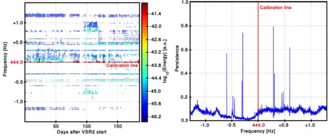
for CW signals with unknown parameters is performed over a much larger parameter space [20] (all-sky, GW frequencies between 20 Hz and 2 kHz, and for several possible values of the spin-down rate) which reduces the sensitivity of the search. Broad-band increases of the detector noise level are the first obstacle for CW searches [21]. This paper, however, focuses on narrow-band frequency disturbances called spectral lines (or lines). The presence of lines in the detector frequency spectrum can significantly reduce the sensitivity of CW searches. The origins of several lines in the Virgo sensitivity curve (figure 2) are well-known. Some of these lines are associated with resonances of different detector components, including the mirrors (“drum modes”) or the suspension wires (“violin modes”). This family of lines is part of the detector design and cannot be removed from the data. There are also constant frequency signals which are injected into the detector for calibration and control purposes. This paper focuses on a second class of lines which are more problematic since many of them have no identified origin or they cannot be mitigated easily without degrading the general performance of the detector. Furthermore, some of these noise lines are not stationary; they fluctuate in amplitude and frequency, making their identification more complicated. These non-stationarities can also be a source of glitches that affect transient GW searches. It is thus important to track the noise spectral lines, to monitor their characteristics (frequency, amplitude and variability) to ensure that they do not cross the frequency band of a known pulsar. Both LIGO and Virgo have dedicated data-analysis tools to achieve this task and to help identify the sources of noise lines [22, 23, 24, 25].
A stochastic gravitational wave background (SGWB) is expected to be emitted in the early stages of the universe evolution (by inflation [26], electroweak phase transition [27] and cosmic strings [28]) or produced as a consequence of the incoherent superposition of many astrophysical sources like core collapse supernovae [29], magnetars [30] or neutron star coalescence [31]. SGWB searches correlate two detector’s strains over a wide frequency range [32, 33] and are also affected by noise spectral lines. The SGWB search is also sensitive to large transients which distort the estimation of the detector frequency spectrum used to measure the signal. The published SGWB search involving Virgo [34] made use of the data-quality work described here for transient searches to reject the most noisy time periods for the analysis.
This paper gives an overview of the data-quality studies carried out during the three Virgo science runs designated as VSR1, VSR2 and VSR3 which occurred during 2007-2010 (see table1). Many noise sources were identified by our investigations and we describe the actions taken to mitigate noise or the procedure used to veto remaining noise events. The paper is organized as follows: section 2 presents the Virgo detector, its sensitivity to GWs and the different Virgo data-taking campaigns over the years. Several detector sub-systems are also briefly described. In section 3, a summary of the
detector characterization work is given. Section 4 focuses on transient noise sources. We present the different methods which have been developed to identify glitches, we list the noise sources which have been identified and we explain how they couple with the strain output. This section also describes the actions to remove glitches either at the detector level or from the data-analysis, with the definition of data quality flags. Noise spectral lines, which primarily affect CW and SGWB searches, are discussed in section 5. Methods for identifying lines are briefly described and we review the main families of lines. Finally, section 6 shows how the Virgo detector characterization work impacts the transient GW and CW searches involving Virgo data. We conclude with section 7, where we present ideas for improvement of the detector characterization tools and procedures for the next generation of GW detectors.
2. The Virgo Detector
Virgo is an interferometric GW detector located near Pisa, Italy, aiming at directly
observing GWs. The optical layout of the detector is based on a power-recycled
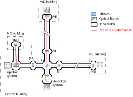
Michelson interferometer where each arm contains a 3-km long Fabry-Perot cavity. The Virgo experiment layout is shown on figure 1. An incident GW from a plausible
astrophysical source induces a differential length variation (smaller than 10−18
m) between the test masses suspended at both arm ends. The interferometer is set to operate at a dark fringe and photo-diodes at the output of the interferometer observe a GW signal as a fluctuation in the intensity of the light. In the following we will often refer to the dark fringe (DF) as the uncalibrated GW detection channel. The calibrated GW strain amplitude, h(t), is reconstructed taking into account the frequency-dependent transfer functions of the instrument [35, 36] which are applied to the DF signal. The ability to detect GWs relies on the stability of the detector, and much attention is given to critical systems of the instrument: the mirrors, laser and feedback controls.
The isolation of the test masses from seismic activity is crucial in order to ensure good sensitivity, especially at low frequencies. In Virgo, sophisticated super-attenuators (SA) [37] have been installed to decouple mirror motion from seismic fluctuations. A SA consists of an eight meter chain of five mechanical pendula with a connection to the ground by three elastic legs, playing the role of an inverse pendulum. The bottom part of the suspension, called the payload, is composed of mechanical elements that suspend the mirror and control its motions. This payload is suspended from the last stage of the SA. The SA allows for good sensitivity down to 10 Hz.
The main laser (a 1064 nm Nd:YaG laser [38]) is a critical component of the interferometer and special attention must be given to its stability and its operation. The laser frequency and power are stabilized and the laser position jitter is controlled to limit the impact of environmental disturbances [39]. A suspended 144 m triangular cavity, called the Input Mode Cleaner (IMC), is used to remove high-order modes from the light. The laser propagation takes place inside a high-quality vacuum to limit air contamination which could induce phase noise. Scattered light represents a major
Figure 1. The Virgo detector layout showing the main laser path through the input mode cleaner (IMC), the power recycling mirror (PR), the beam splitter (BS), the western cavity (WI-WE), the northern cavity (NI-NE) and the detection system. Most of the laser propagation is performed in high-vacuum [4].
contribution to the Virgo noise since it can recombine with the main laser beam. Such an effect is limited by installing beam dumps and baffles at strategic points inside the vacuum tanks [40].
The optical cavities are maintained at resonance using the Pound-Drever-Hall
technique [41], relying on a laser beam phase-modulated at 6.26 MHz. DC and
demodulated signals from different photo-diodes throughout the detector are used to control the interferometer. The control loops, running at a sample rate of 10 kHz, are composed of Analog to Digital Converters (ADC), and a real-time software architecture that is used to reconstruct the cavities length. The control system also sends corrections to the mirror actuators (coils in front of magnets) through Digital to Analog Converters (DAC) to keep the optical cavities resonant. Special care is taken to keep the electronic noise at a very low level and to insure a reliable synchronization between the different control processes involved in the feedback systems [42, 43].
Virgo can detect GWs with an amplitude as low as 10−21
over a wide frequency
band, from tens to thousands of hertz (and below 10−22
at a few hundreds of hertz). The sensitivity curves shown in figure 2(b) are limited by several types of noise that can be divided into three frequency regions. At low frequencies (below 100 Hz), the sensitivity is limited by mirror and suspension thermal noise, mirror control noises, and environmental noises. Mirror control noise refers to the noise introduced by the feedback systems used to maintain the interferometer alignment and resonance. This noise originates from the actuators’ electronics and from the control system’s error signals. Environmental noise includes seismic and acoustic disturbances coupling into the interferometer through scattered light or input beam jitter, as well as magnetic
Figure 2. (a) Typical sensitivity vs. frequency curves for the first three Virgo science runs: VSR1 (2007), VSR2 (2009) and VSR3 (2010). (b) The measured VSR2 sensitivity curve is compared to the predicted noise budget [44]. The agreement between the measured and the predicted sensitivity was the best for VSR2. For VSR1&3 the agreement was not as good, especially at low frequency.
disturbances coupling through the mirror magnets. At high frequencies (above 300 Hz) the sensitivity is primarily limited by the shot noise of the main laser beam and by laser frequency noise. The frequency noise originates from the shot noise of the sensor delivering the error signal used in the laser frequency stabilization. For intermediate frequencies (between 100 Hz and 300 Hz), both thermal noise and shot noise limit the sensitivity. Noise structures around 165 Hz and 210 Hz are suspected to originate from scattered light (see section 4.2.6).
In addition to achieving a good sensitivity, it is also important to maintain the detector in operation as long as possible in order to maximize the live-time (or duty cycle). A lock acquisition scheme [42, 43] was designed to bring and maintain the Virgo detector to its working point. The Virgo locking procedure has proved to be very efficient and robust. The lock can last for several hours or days at a time (see table 1). If lock is lost, it can be recovered in a few minutes. When locked, the detector is manually set in science mode when a stable state is reached. When in science mode, no external input or detector tuning is allowed. Science mode ends when decided by the detector operator (for maintenance or tuning) or whenever an instability causes loss of lock of the interferometer. The beginning and the end of a lock segment are considered unsafe in terms of data quality. Thus, the first 300 seconds after the end of locking procedure and the 10 seconds of data before the loss of lock are, a priori, rejected and not used for science analysis.
The first Virgo science run, VSR1, took place between May and October 2007, in coincidence with the LIGO detectors. The second run, VSR2, started in July 2009 after a commissioning period devoted to detector upgrades. These upgrades included: more powerful and less noisy read-out and control electronics, a new laser amplifier that provided an increase of the laser power from 17 to 25 W at the input port of
Virgo Science Runs VSR1 VSR2 VSR3 Date May 18, 2007 Jul 07, 2009 Aug 14, 2010
→Oct 01, 2007 →Jan 08, 2010 →Oct 20, 2010
Duty cycle (% of lock time) 81% 80% 73%
Science time 108 days 149 days 50 days Average lock duration 10 hours 10 hours 9 hours Max lock duration 94 hours 143 hours 63 hours Omega average trigger rate (SNR > 5) 2.1 Hz 0.6 Hz 1.8 Hz
Table 1. Virgo runs summary information. Omega [45] triggers are generated online to estimate the rate of transient noise events.
the interferometer, and the installation of a thermal compensation system (TCS) [46], to reduce the effects of thermal lensing in the arms’ input mirrors. As a result, the detector sensitivity was much improved with respect to the previous run, as can be seen on figure 2(a). VSR2 lasted six months, after which further upgrades were performed. Higher reflectivity mirrors were installed to increase the finesse of the Fabry-Perot cavities. As a test for Advanced Virgo [47], these mirrors were hung by a new suspension made of monolithic silica-fibers in order to reduce thermal noise effects [48]. These detector upgrades took six months before resuming science with VSR3 from August to October 2010. The resulting sensitivity in VSR3 was not as good as expected, however, and was slightly worse than VSR2. It was not possible to obtain a reliable noise budget in VSR3. It was discovered that the newly-installed mirrors had a large asymmetry in the radius-of-curvature and losses. This increased the interferometer’s contrast defect, resulting in higher power in the DF and stronger couplings to some noise sources. This paper focuses on the detector characterization work performed during the three first Virgo science runs. A final run, VSR4, occurred in 2011 for which very few references will be given in the following. Table 1 summarizes the performance of the Virgo science runs covered in this paper.
3. Detector characterization
The power spectral density shown in figure 2 is an incomplete representation of detector performance as it does not include transient effects which reduce the sensitivity of GW searches. The DF signal can be disturbed by a large variety of noise sources originating from within the detector or from its environment. The noise path (or coupling), which connects the noise source to the DF affects the characteristics of the noise. A long process called “noise hunting” consists of tracking down each noise source and understanding the conversion mechanisms which occur between the source and the DF. To achieve this task, the Virgo detector is equipped with hundreds of sensors, including microphones, seismometers, magnetometers, photo-diodes, current and voltage monitors, thermometers and cameras. The signals from these auxiliary channels are used to monitor external disturbances to help determine whether a candidate event found by a search pipeline was produced by a GW or by an instrumental
artifact. The Virgo noise hunting process can be summarized as the following:
(i) Identify events (glitches or noise spectral lines), or a family of events with similar properties, seen in the DF.
(ii) Correlate this event with some unusual detector behavior or environmental disturbances (human intrusions, earthquakes, thunderstorms, etc.).
(iii) Check the event time against external scheduled events, such as the stop/start of infrastructure machineries or changes in the interferometer running configuration. (iv) An extensive study is performed to tell whether the event occurred in time
coincidence with an event in one or several auxiliary channels. Statistical algorithms are used to quantify the correlations between auxiliary channels and the DF, see sections 4.3 and 5.1 for more details.
(v) In many cases, the previous studies cannot differentiate whether the noise has been identified at its source or somewhere along its propagation. Experiments are performed to understand how the noise couples into the DF signal. For example, one can artificially inject noise in a hardware component and study the response of the detector [49]. Another possibility is to switch off a potential noise source to see if the noise disappears. Some examples of such actions are given in sections 4.2 and 5.2.
(vi) If a noise source is identified, the strategy to remove it from the DF is twofold: first we try to eliminate or reduce the noise sources; second, we try to reduce the coupling to the DF.
An important aspect of detector characterization is reaction time. When a problem occurs while Virgo is acquiring data, if we can understand the source of noise quickly, we can make appropriate modifications to the detector or its environment to mitigate the noise. To this end, many algorithms are run online which monitor the detector’s data quality. The strain signal is analyzed by various search pipelines to characterize the type of events that limit the sensitivity of the searches. Auxiliary signals are monitored in quasi-real time so as to be able to tell if they are linked to events found in the GW searches. The loudest glitches and noise spectral lines are studied, common features are searched for, and cause-effect relationships are investigated. For VSR2 and VSR3, data was analyzed shortly after it was collected so the commisioning groups could mitigate the noise source/coupling as quickly as possible. Depending on the noise complexity, mitigation actions could last from a few hours to a few days. Interactions between analysis and commissioning groups are imperative to make the noise hunting process efficient.
Because many noise sources cannot be clearly understood or mitigated, they must be identified and tagged in the data. These events will be vetoed when data are processed by search pipelines with data quality flags.
For transient searches, data quality investigations consist of defining lists of time segments of a few seconds long (commonly called DQ flag segments) where there is a high
probability that a glitch is caused by an instrumental or environmental source. A DQ flag is usually defined by using an auxiliary signal that indicates that the interferometer was out of its proper operating condition or that an external disturbance was present. Any event found during flagged times by the data analysis pipelines are vetoed [50, 51, 52] (see section 4.3).
For CW searches, data quality investigations consists of tagging, characterizing and tracking noise spectral lines. Algorithms are used to establish coincidences between lines in the detector output and auxiliary channel signals. This information is then used by the search to reduce the number of false CW candidates (see 5 and 6.2).
All of the data quality information is stored in databases [53, 54]. In addition to reliably archiving data, the Virgo database may also be used to perform specific queries. DQ flags and noise lines can be retrieved by analysis pipelines or through a web interface.
4. Transient noise sources 4.1. Investigations
In Virgo, two analysis pipelines are run online, Omega [45] and MBTA [55], which monitor the data quality for transient GW searches in quasi-real time. Omega is a burst search algorithm which produces triggers based on a sine-Gaussian excess power method with frequencies between 48 and 2048 Hz. A discrete Q transform is applied which consists in tiling the time-frequency plane for a specific quality factor value. For each tile, it is possible to define a central time, a central frequency, a duration and a signal-to-noise ratio (SNR) which is simply the ratio of the total energy content of the tile to the power spectral density of the detector noise. The Omega algorithm is generic enough to produce triggers which are a reliable representation of the output of any transient GW search. Omega is sensitive to typical detector glitches and provides useful information about the glitch properties. Omega triggers are often the starting point for glitch investigation, and special attention is given to high-SNR events. The noise coupling associated with loud events is expected to be more obvious, and therefore easier to understand. Moreover, mitigating or vetoing loud noise events should also remove quieter glitches which are due to the same noise source. The MBTA pipeline was specifically designed to detect GWs associated with the coalescence of compact binary objects. An inspiral waveform template bank is used to match-filter the data. The intercorrelation between the data and the template, weighted with the inverse of the noise power spectral density, defines the event SNR. The glitches detected by the MBTA pipeline are not as generic as the ones produced by Omega since these glitches mimic the specific properties of a CBC signal. However, MBTA triggers give a reasonable sample of the type of glitches that may affect CBC searches.
A glitch detected by Omega or MBTA often results from a sudden environmental perturbation that then propagates through the detector, reaches one of the Virgo
sub-systems sensitive to this kind of perturbation, and then couples to the DF signal. For example, an acoustic disturbance can be converted into mechanical vibrations which can, in turn, affect optical elements or disturb the main laser propagation. Auxiliary channels are constantly monitored and analyses are performed to establish the correlations between glitches in the auxiliary channels and triggers produced by Omega or MBTA (glitch-to-glitch identification). In this way, the most relevant channels are identified, the noise path may be reconstructed, and the noise sources identified.
Some glitches detected by Omega or MBTA can result from a spectral line in the DF which becomes non-stationary in amplitude or in frequency because of fluctuations in the coupling to the noise source (for instance, alignment fluctuations). This effect can be particularly harmful for searches using data whitening procedures (normalization by the detector frequency spectrum) since they amplify slight amplitude variations of spectral lines. For this type of noise, a glitch-to-glitch coincidence with auxiliary signals does not normally identify the coupling and allow us to construct a DQ flag. However, the frequency of the line can help identify the noise source and hence the coupling.
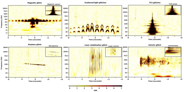
One additional functionality of Omega is its ability to scan a large number of channels and plot the excess energy as a function of time and frequency [45]. This represents a powerful tool to identify families of glitches based on the common patterns of the time-frequency map. Since this process is computationally expensive, it is typically performed only for the strongest glitches or for a particular class under investigation. When establishing the coincidences between channels, it is then possible to reconstruct the noise path for a given family. Figure 3 shows an example of Omega scans of six well-identified families of glitches. For five of these families, a glitch seen in an auxiliary channel allowed us to identify the coupling between the noise and the DF signal.
Most of the detector characterization tools, like Omega scans, were designed to study glitches resulting from linear couplings between the noise source and the DF. Within this framework, a noise source can be identified only if it produces a glitch somewhere on the noise path that could be detected in an auxiliary channel. For example, the scattered-light glitches shown in figure 3 do not trigger other auxiliary channels. Understanding a noise source outside this glitch-to-glitch description is a much harder task. Non-linear couplings are believed to play a major role in the production of noise in the detector. Only a few of these non-linear noise processes have been identified and this requires a deep understanding of the experimental details of the interferometer. Some non-linear couplings will be described in section 4.2.
4.2. Glitch sources and couplings
4.2.1. Seismic glitches. Seismic activity is probably the most pervasive source of noise
in Virgo, affecting the detector in many different ways. Almost every Virgo sub-system is sensitive to sufficiently large vibrations. Seismic noise can produce a large variety of glitches which are very difficult to track. Loud seismic glitches due to violent shocks or earthquakes are likely to produce noise in the DF. If this happens, the data recorded
Figure 3. Omega time-frequency maps of six examples of glitches seen in the DF channel. Glitch families are identifiable by their unique time-frequency morphology. When identified, the glitch in the auxiliary channel is shown in the inset plot. The first plot shows a 50 Hz power-line glitch also detected by the magnetometers. The second map shows a series of glitches caused by scattered light induced by seismic activity. The third glitch is caused by a TCS instability. The fourth plot presents an airplane event with a clear Doppler effect. The fifth event is due to a glitch in the laser stabilization loop. The last glitch with an undefined shape is due to a seismic event up-converted to higher frequencies.
during a seismic event is rejected and so the noise coupling is less relevant. The low frequency signals collected by the multiple seismometers and accelerometers on site are used to define DQ flags for large seismic activity. Several frequency bands are monitored at all times, from 0.25 Hz up to 16 Hz. A priori, such low-frequency seismic glitches should not be an obstacle for the transient GW searches whose frequency band usually starts above 40 Hz. However, seismic noise is often up-converted in frequency, for example through scattered light mechanisms as described in [56]. For example, the seismic glitch presented in figure 3 was detected by the seismometers at about 8 Hz and is seen in the DF signal at much higher frequency (∼ 200 Hz).
Bad weather conditions can increase the seismic activity and cause significantly deteriorated data quality. In such conditions, the Omega pipeline shows an excess of triggers at low frequency (typically below 100 Hz). In the case of very bad weather, the Omega trigger rate below 100 Hz can increase by a factor 5 to 7. During the winter, VSR2 showed many periods of high seismic noise. Substantial efforts were devoted to studying the resulting glitches [56]. One family of scattered-light glitches was characterized by no visible glitch in the Omega time-frequency maps of the seismic sensors. This fact indicates that a non-linear coupling was in action. The time-frequency shape of these triggers is very well-recognizable (see the second plot of figure 3). It consists of a series of arch-shaped glitches that can last several seconds. The glitches
are caused by light scattered by e.g. the tower walls or the suspended baffles moving with the micro-seismic motion of the ground. When the micro-seismic activity is large, higher harmonics can be seen, probably due to multiple-bounce optical paths. In such conditions, several rows of arch-shaped glitches can be seen in time-frequency maps. This noise is well-modeled and the frequency of the arches is proportional to the velocity of the scattering object. Tests showed that the position sensors installed at the top stage of the suspensions are well suited to measure the velocity. The scattered-light glitches can be rejected when thresholding on the measured velocity. When applying the DQ flag created in this way, 8% of the science time is lost but 2/3 of the scattered-light glitches were vetoed. The coupling mechanism for the scattered-light glitches was understood during VSR2 when it was noticed that most of the scattered light was re-injected into the beam at the level of the west-end optical bench. For VSR3 the number of scattered light glitches decreased because of the lower transmission of the new end mirrors and the installation of absorbing baffles in the west-end tube.
4.2.2. Acoustic glitches. Acoustic disturbances can mechanically affect the Virgo
systems and produce glitches. Acoustically-isolating enclosures have been installed around each optical bench in order to limit the acoustic coupling with the environment. However, acoustic pollution can either be produced inside the enclosure or can get inside through mechanical vibrations. To monitor acoustic noise, each building is equipped with several microphones. Most of the time, the acoustic disturbances originate from mechanical devices located near the interferometer which can be mitigated. However, acoustic noise can also have an external origin which cannot be controlled or suppressed. Several times during the day, airplanes or helicopters fly over Virgo and they are seen in the DF signal. These glitches can be clearly identified by the typical Doppler shift at about 100 Hz seen in time-frequency maps of the detector output (see an example in figure 3) [57].
4.2.3. Electrical glitches. Electrical cables represent a major source of noise coupling
since they can propagate an electrical disturbance throughout the Virgo site. The Virgo sub-systems are usually designed to be electrically isolated from the environment. However the 50 Hz mains frequency (European standard) can couple into the detector and transmit magnetic transients. For example, during VSR2, it was noticed that a family of glitches was periodically produced roughly every 15 minutes. This effect was identified as electrical coupling of an air-conditioning unit switching on and off. During the winter period of VSR2 a loud glitch was produced every day at 8am due to the heating system that switched on at the beginning of the day and drew a significant amount of current. Such glitches can be vetoed by using magnetic sensors that are sensitive to electrical transients. Electrical glitches are usually corrected by breaking the electrical noise path. In the two specific cases here, the glitches disappeared after upgrades to the detector electronics.
4.2.4. Main laser glitches. One critical element of the Virgo detector is the main laser injection system. This system contains many control loops to stabilize the laser power and frequency. Failures in these control systems caused various families of glitches. During VSR3, the laser power stabilization control loop was experiencing saturations due to a mis-tuned gain. This created strong broadband glitches from tens to thousands of Hz (see figure 3). This was fixed a few days after the problem was discovered. In the meantime a specific DQ flag was built to monitor the control loop channel and to efficiently exclude the glitches from the data attributed to the control failure.
4.2.5. Dust glitches. Most of the laser light propagation is done in a high-quality
vacuum. However the beam propagates through air in some parts of the detector, for instance on the injection and detection benches. Some disturbances, due to dust crossing the beam, for example, create glitches which are difficult to veto. The laser light propagation can also be disturbed by unexpected events like spiders building webs or bugs flying through the beam. It is possible to limit such pollution by protecting the laser path with plastic covers. Some of the remaining glitches can be vetoed by using the photo-diode signals of the secondary beams which are not sensitive to GW signals. Many DQ flags were created in this way. A very efficient veto was introduced in VSR1 which relies on the fact that a real GW event seen in the in-phase demodulated DF channel should not be visible in the quadrature channel if the demodulated phase is well-tuned. This PQ veto [58] has been extensively used to eliminate these potential “dust events” in the Virgo data.
4.2.6. Alignment glitches. The alignment of the main optical beam is critical in order
to maintain the detector in operation. Sophisticated feedback systems are required to continuously control the optical component angular degrees of freedom and to optimize the laser beam alignment [59, 60]. In the Virgo sensitivity curves shown in figure 2(a) several spectral lines are known to correspond with resonances of some optical mounts of the detection bench (165, 210, 420, 495 and 840 Hz) and are due to light scattered by these optical components. In principle they should not be seen as glitches unless they suddenly vary in amplitude which can happen when the interoferometer alignment conditions change. This effect of non-stationary lines is a well-known source of glitches to which transient GW searches are very sensitive. In Virgo, alignment glitches represent a quite large fraction of Omega triggers (about 25%). In the case of bad weather, alignment fluctuations are even larger. As a result, the fraction of glitches due to alignment reaches 40% and the amplitude of the glitches increases. Alignment signals can be used to build DQ flags to suppress these alignment glitches. For VSR2 and VSR3, large deviations of the mirror angular positions were flagged. This allowed for the removal of as much as half of the alignment glitches.
4.2.7. TCS glitches. The thermal compensation system [46] was installed in Virgo
producing a thermal or a radiation pressure disturbance at the mirror level. During VSR2, the TCS laser has been stabilized, reducing the number of glitches. However, it was necessary to build a specific DQ flag, using the channel monitoring the TCS power, to veto the remaining glitches. Figure 3 shows an example of a TCS glitch that is vetoed by a DQ flag.
4.2.8. Saturation glitches. Very loud glitches can be produced by the saturation of
different Virgo active systems. For instance, every photo-diode must operate within its nominal range (±10 V). Specific DQ flags have been introduced to reject noise transients whenever a photo-diode voltage is out-of-range. Similarly, the mirror coil driver currents are monitored to check for saturations.
4.2.9. Tilt glitches. In data taken two years before the first science run, we identified
a non-linear coupling between the dark fringe and the laser frequency noise. Laser frequency noise usually lies well below the shot noise level at high frequencies (see figure 2(b)). Every 27 s, broadband glitches were visible in the DF signal. This period corresponds to a mechanical resonance in the lower part of the mirror suspension. The periodic noise increase was correlated with the extremal angular tilt of the Fabry-Perot cavity’s mirrors. When the mirrors are badly aligned the coupling of the laser frequency noise increases. To cure this problem, the mirrors’ alignment control loops have been greatly improved. A veto using the direct measurement of the laser frequency noise in the DF signal (a line at 1111 Hz was injected in the laser frequency control system) was created to efficiently eliminate all of the periods containing this noise [61].
4.2.10. Piezo glitches. The Virgo detector has many piezo-electric drivers used to
control various elements of the beam path. At the beginning of VSR1, one of the four piezos of the beam monitoring system was malfunctioning, causing the input beam to jitter [62]. This jitter can couple to interferometer asymmetries and was a source of glitches in the DF signal. The typical frequency of theses glitches was around 150 Hz. This problem was discovered during the first month of the run and the piezo was replaced two months later. A similar problem occurred during VSR3 at the output mode cleaner. A piezo voltage was found noisy for several hours. The faulty piezo elements were fixed but DQ flags, based on the control channels, were defined in order to completely exclude the glitches from the data recorded while the piezo was faulty.
4.2.11. Mirror glitches. During VSR2, some glitches were observed with the distinctive
feature of an abrupt step in the h(t) time series which resulted in a loud broadband disturbance. Theses glitches were demonstrated to be associated with an excitation of the internal modes of the west-input (WI) or west-end (WE) mirrors (depending on the glitches), identified by their accurately known frequencies. The glitches were interpreted as a sudden displacement of the surface of those mirrors, of unknown origin. In the case of the WI mirror, the glitches appeared after the magnets glued on the back
of the mirror were replaced using a type of glue that had not been used before for that purpose, suggesting the possibility of a creeping mechanism in the hygroscopic glue. It was not possible to firmly confirm this suspicion, and the cause of the WE mirror noise still lacks a convincing explanation. It was impossible to safely veto those glitches, due to the lack of independent auxiliary information.
4.2.12. Thermo-mechanical glitches. The external temperature can also be an indirect
source of glitches. The steel vacuum tubes, in which the laser travels, have poor thermal isolation. Hence, external temperature variations are very likely to mechanically stress the tube through contraction and expansion. During VSR4, it was understood that when the expansion/contraction force exceeds the static friction which holds the tube on its support, a sudden shock occurs and a mechanical vibration propagates along the tube. This effect is the strongest around noon and midnight when the temperature gradient is the largest. Seismometers have been installed to track the noise propagation and it was found that the noise source was the tube between the IMC and the injection tower. The resulting glitches are produced in the DF signal at about 80 and 160 Hz. A seismometer placed on the injection tower allowed us to flag these glitches with high efficiency.
4.2.13. Radio frequency glitches. High-frequency electromagnetic noise overlapping
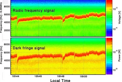
with the laser modulation frequency (6.26 MHz) can be picked up by the DF photo-diode signal before demodulation. It can then enter the detector’s sensitive band after demodulation. High-frequency electromagnetic transients are generated, for example, by fast switching electronic devices (i.e. power supplies with a typical switching rate of 100 kHz and above), and by data flow to/from digital devices (the clock rate of communication protocols is typically in the MHz range). During VSR2 the 6.26 MHz modulation signal was intermittently polluted by a large amount of glitches that were also seen in the DF signal. The origin of this noise has never been identified, mostly because of its intermittent nature. The noise was suspected to originate from serial transmission devices. It was possible to build a DQ flag based on the modulation signal to remove the glitches seen in the DF signal. The beginning of VSR3 showed a large excess of Omega glitches at high frequency (at 1 kHz and beyond). This was identified as a result of a coupling between the modulated DF signal and an electromagnetic field whose frequency was close to the modulation frequency (see section 5.2.2 for more details).
4.2.14. Digital glitches. The Virgo interferometer is kept at its working point by various
digital control loops. The control servos dedicated to longitudinal control are fast control loops running at 10 kHz and any digital problem occurring in theses systems can directly affect the DF signal. One example is a set of loud glitches in VSR1 that were due to a loss of synchronization in the control system. This led to dropped samples between the global control system (which provides the 10 kHz signals for the interferometer’s
longitudinal control) and the Digital Signal Processing board in charge of filtering the correction signal before it is sent to a mirror’s coil. Combined with a strong but harmless 5 kHz oscillation that is sometimes present in the control signals, the dropped samples produced loud glitches which were vetoed offline by searching for missing samples within the 5 kHz noisy time periods.
4.3. Data quality flagging
In the previous section, the sources of transient noise, which were identified during the first three Virgo science runs, were listed. As the sources were understood and localized, the commissioning team tried to fix the noise sources when possible. However, it was necessary to create a dedicated DQ flag to veto the glitches before the fix was performed or when a repair was impossible.
As explained previously, some DQ flags were created by monitoring a given set of auxiliary channels indicative of noise perturbations (seismic, acoustic, etc.). The same procedure is used for many DQ flags: it consists of computing the frequency spectrum of a given auxiliary channel and to extract the RMS in a specific frequency band (band-RMS). If this RMS exceeds a given threshold, the data are flagged as noisy. Many generic seismic flags are generated online in such a fashion. About 30 seismic sensors are monitored in different frequency bands: 0.25-1 Hz for the weather conditions, 1-4 Hz for the car traffic activity and 4-16 Hz for the human activity. Acoustic and magnetic disturbances are monitored the same way. This kind of environmental DQ flag does not necessarily point toward a glitch in h(t) but corresponds to a weaker statement: “an environmental disturbance was present in the vicinity of the detector”.
When the noise path to the DF has been understood, it is possible to use more specific procedures to create a DQ flag that deals with a category of glitches and which has a great predictive behavior (measured by the use-percentage defined in section 4.3.2). In other words, when a time period is flagged the probability to find a glitch in the GW data has to be high. A good DQ flag has to be selective but also efficient (it must not miss too many glitches of the same class). Section 4.2 gives many examples of DQ flags created to veto specific glitches. Sometimes these flags rely on a band-RMS where the parameters have to be carefully tuned. In some cases a simple threshold on the channel value is enough to give good flag performance. There are also some examples where DQ flags had to be specifically tailored for a given family of glitches. In section 4.2.1 we gave the example of the scattered-light glitches where the velocity of the scatterer was used to create the flag. Sometimes it is necessary to combine several channels. One example of this was the DQ flag created to monitor glitches produced by the large angular deviations of the mirrors (section 4.2.6). Multiple mirror degrees of freedom had to be combined to produce an effective DQ flag. Finally, in some cases, it has been necessary to use several channels in time coincidence to provide a DQ flag with good selection abilities. For instance the 50 Hz glitches, detailed in section 4.2, are usually seen all over the Virgo site in the magnetic sensors. Therefore the corresponding DQ
flag is defined as a time coincidence between the band-RMS excesses obtained from several auxiliary signals.
Another method to perform glitch flagging relies on a statistical approach and does not require any knowledge about the noise source or the coupling. In this method, we systematically look for noise excess in many auxiliary channels and correlate it with glitches in the GW data. For this purpose, the KleineWelle (KW) algorithm [63] is used to produce triggers for more than 500 Virgo auxiliary channels with a very low latency. As for Omega, the KW algorithm searches for a statistically significant excess of power in the time-frequency plane but it relies on a wavelet transform instead of a Q transform. Omega is known to better estimate the trigger parameters like the frequency or the SNR. However, Omega runs much slower than KW which explains why KW was chosen to perform the auxiliary data analysis. KW triggers are then used by algorithms such as use-percentage veto (UPV) [64] or hierarchical Veto (hVeto) [65] to establish coincidences between triggers of a given auxiliary channel and GW triggers. When the number of coincidences is much larger than the expected rate of random coincidences, the channel is selected as interesting in order to define a powerful veto. By construction, a KW-based veto does not result from an understood coupling mechanism. For this reason, this type of vetoes are considered less reliable. This statistical approach is not only good in terms of glitch flagging but it can also be a great tool for the glitch investigation. By identifying the auxiliary channel that best correlates with the DF, this method can help understand the origin of glitches. In this case, the KW-based veto was used to construct a DQ flag using a band-RMS of the channel of interest.
Finally, some DQ flags are defined manually by the scientist on shift in the Virgo
control room or at a later time. These DQ flags often refer to serious detector
malfunctions or disturbances in detector operation. Thunderstorms or earthquakes are systematically reported and the corresponding time segments are saved for future reference. The detector operation logbook [66] is also carefully examined and when a Virgo sub-system failure is reported, a specific DQ flag is created. For example, several DQ flags were defined based on photo-diode, TCS or data-acquisition malfunctions.
In the following, all flags and vetoes described above, including the PQ veto, are called DQ flags. When designing a DQ flag, one should always keep in mind that the flag must not couple to a real GW event (i.e. the flag is safe for the GW events), while, at the same time, it must efficiently eliminate noise transients (the flag has good performance). Those two important aspects are described in the next two sections.
4.3.1. Data quality flag safety. All vetoes, except the PQ veto [58], are derived from
channels that are assumed to be independent of the DF (which may contain a GW signal). By accident, a veto can dismiss a genuine GW signal, but the probability of such an event must be small and follow the Poisson probability of coincidence between two random processes. To test that a veto is safe, fake GW signals are injected into the interferometer by applying a force on one mirror of one Fabry-Perot cavity to mimic the path of a GW event (hardware injections). Different types of signals are injected, but

![Table 1. Virgo runs summary information. Omega [45] triggers are generated online to estimate the rate of transient noise events.](https://thumb-eu.123doks.com/thumbv2/123doknet/14252093.488331/15.918.133.760.130.294/table-virgo-summary-information-triggers-generated-estimate-transient.webp)