HAL Id: hal-01176051
https://hal.archives-ouvertes.fr/hal-01176051
Submitted on 5 Oct 2015
HAL is a multi-disciplinary open access
archive for the deposit and dissemination of
sci-entific research documents, whether they are
pub-lished or not. The documents may come from
teaching and research institutions in France or
abroad, or from public or private research centers.
L’archive ouverte pluridisciplinaire HAL, est
destinée au dépôt et à la diffusion de documents
scientifiques de niveau recherche, publiés ou non,
émanant des établissements d’enseignement et de
recherche français ou étrangers, des laboratoires
publics ou privés.
Modeling Aircrafts Operational Reliability
Kossi Tiassou, Karama Kanoun, Mohamed Kaâniche, Christel Seguin, Chris
Papadopoulos
To cite this version:
Kossi Tiassou, Karama Kanoun, Mohamed Kaâniche, Christel Seguin, Chris Papadopoulos.
Model-ing Aircrafts Operational Reliability. International Conference on Computer Safety, Reliability ans
Security (SAFECOMP 2011), Sep 2011, Naples, Italy. pp.157-170. �hal-01176051�
Modeling Aircrafts Operational Reliability
Kossi Tiassou1, 2, Karama Kanoun1, 2, Mohamed Kaâniche 1, 2, Christel Seguin3,Chris Papadopoulos4,
1CNRS; LAAS; 7 Avenue du Colonel Roche, F-31077 Toulouse Cedex 4, France
2 Université de Toulouse; UPS, INSA, INP, ISAE; UT1, UTM, LAAS; F-31077 Toulouse
Cedex 4, France {firstname.lastname}@laas.fr
3ONERA/DCSD/CD, 2 Avenue Edouard Belin, 31055 Toulouse Cedex 4, France
4AIRBUS Operations Ltd., New Filton House, Golf Course Lane, Filton, Bristol, BS99
7AR, United Kingdom [email protected]
Abstract. The success of an aircraft mission is subject to the fulfillment of some operational requirements before and during each flight. As these requirements depend essentially on the aircraft system components and the mission profile, the effects of failures can be very significant if they are not anticipated. Hence, one should be able to assess the aircraft operational reliability with regard to its missions in order to be able to cope with failures. This paper addresses aircrafts operational reliability modeling to support maintenance planning during the mission achievement. We develop a modeling approach to represent the aircraft system operational state taking into account the mission profile as well as the maintenance facilities available at the flight stop locations involved in the mission. It is illustrated using Stochastic Activity Networks (SANs) formalism, based on an aircraft subsystem.
Keywords: operational reliability, model-based assessment, aircraft system, maintenance planning
1
Introduction
With the increasing interest in air transportation and the competitive market aircraft operators have to deal with, aircraft operational disruptions become a key concern in the aviation field. In order to avoid economical losses due not only to inoperability but also to customer dissatisfaction, airlines need to anticipate on the events that may disrupt the achievement of their aircrafts missions. Aircraft missions are achieved in compliance with operational requirements depending principally on the current operational state of the aircraft system components and the mission profile. Thus, an attention must be paid to the effects of the aircraft system component failures and the corresponding maintenance actions. Failures that may disturb the achievement of the aircraft mission must be handled with adequate corrective actions. However, the ability to promptly cope with these failures depends on the location where they occur.
Maintenance facilities are not the same at all airports. Generally, airlines have more facilities at their main base than at the other airports. Therefore, the maintenance resources must be adapted to the aircraft missions. The issue is to have an assessment method that can support mission assignments and maintenance activities forecasting. Model-based dependability assessment is well suited to support this process.
Our work aims at developing an assessment approach, based on dependability modeling, that makes it possible to continuously assess the ability to keep operating up to a given time or location. The model will be used while planning the missions and during their achievement. To plan the mission, the model can be used to estimate the period of time during which the aircraft system can be operated without reaching adverse states. This allows to determine the mission profile the aircraft must be assigned. Once a mission is assigned to the aircraft, the model can be used during its achievement to assess the ability to succeed in continuing on the remaining part of the mission. The model can also support maintenance activities planning. The best maintenance strategy can be determined comparing the probabilities to accomplish the missions considering different alternatives.
To cover these issues, the model should be able to take into account the various situations in which it may be used. Our approach consists in developing generic stochastic sub models that can be dynamically updated and configured to represent the current state of the aircraft, with regard to the mission to achieve.
The remainder of this paper is structured as follows. Section 2 describes how aircraft missions are carried out together with the verification of the operational requirements fulfillment. Section 3 presents some related works. Section 4 is devoted to the modeling approach, which is implemented in section 6 using an aircraft subsystem as example. The subsystem is presented in section 5. Section 7 presents an example of evaluation result. Finally Section 8 concludes the paper.
2
Description of Mission Achievement
The achievement of the mission is such that each flight is followed by a stop where the aircraft is prepared for next flight. The preparation for the next flight consists of routine maintenance activities, cabin cleaning, catering, baggage and cargo processing, and passenger boarding.
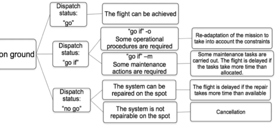
At each stop, the aircraft is inspected and the discrepancies that are reported during the previous flight are checked. If a component is found inoperative, a dispatch decision is taken regarding the next flight. The flight captain refers to an approved document called Minimum Equipment List (MEL) where the components are listed with the status “go”, “go if” or “no go”:
- The “go” status is the case where the aircraft can fly with the component failed. - The “go if” status allows the flight provided some conditions (on other
components, operational performance and maintenance activities) are fulfilled. This includes a given deadline to repair the component.
- The “no go” status prevents the aircraft from flying. The failed component must be repaired before any flight.
The dispatch is allowed if there is no “no go” and all “go if” conditions are acceptable. When the aircraft does not meet the dispatch requirements following a failure, maintenance activities are initiated in order to solve the problem. The magnitude of the failure effect depends thus on the ability to solve the problem at the considered location before the planned departure time. Actually, the flight is considered delayed only after exceeding a given tolerable time frame. Figure 1 summarizes the possible outcomes of the dispatch decision.
When the dispatch is allowed, the aircraft can depart after passenger, cargo and the other ground service processing. Then, the flight begins by the taxing of the aircraft to runway where the takeoff is initiated. During this period or even after the takeoff, the flight can be aborted as a result of a critical failure. The aircraft then returns back to the departure airport. Actually, during the entire flight, it may be diverted if the aircraft capability is degraded. Procedures, stated in the Flight Manual (FM), the Flight Crew Operating Manual (FCOM) or the Quick Reference Handbook (QRH), are used to determine whether the flight must be diverted or not [1].
The adverse situations while operating an aircraft are operational interruptions, namely flight delays, cancellations, in flight turn-back and diversions. Delays and cancellations occur on ground, while turn-back and diversion occur in flight.
3
Related work
To the best of our knowledge, aircraft operational reliability modeling has been seldom addressed in the literature. The studies carried out are rather concentrated on safety aspects (see [3, 10, 14] for instance), and most works about operational reliability are for design enhancement purpose [2, 13]. In [6], the issues of delays and safety in airline maintenance are addressed. A probabilistic risk analysis model is developed in order to quantify the effect of airlines maintenance policies on their aircrafts operability. A decision support approach to maintenance planning is presented in [7]. That is, thanks to redundancy, the aircraft can continue operating with some equipment inoperative, however, it is time limited and can increase the risk of occurrence of an interruption. The approach proposes a method to schedule the
repairs taking into account some optimization criteria: cost, remaining useful life and operational risks. The approach is based on generating alternatives on which is defined a utility function. It is worth noting that the work does not account for reliability measure. It uses the reliability measure as input. In [1], the operational consequences of system failures are studied using event tree analysis. The paper discusses the possible consequences of failures taking into account the flight phase during which they have occurred. A modeling approach based on the fault trees of the targeted aircraft system is presented in [2], together with a computing algorithm to estimate the bounds of the considered probability measure. The approach considers a series of flight cycles and provides a means to evaluate the probability of occurrence of one of three events at each cycle: “No Go dispatch”, “Accepted Degraded Mode” which corresponds to the case where a “go if” occurs and the airline accepts to perform the corresponding tasks, “Refused Degraded Mode” which is a “go if” that is not accepted by the airline. Note that the paper only deals with dispatch events and does not consider in-flight operational consequences. The probability of failure of more than one component during a flight is also neglected.
Concerning modeling aspects, the problem is generally categorized, with regard to the system, as a Phase Mission System (PMS) problem. Mura and Bondavalli [8] analyze the PMS and present a dependability modeling approach. It is shown that, under some given conditions, the model can be processed using an analytical method. Chew et al. [9] address the problem using the concept of maintenance-free operating periods; the system evolves through a series of phases with no possible maintenance. The developed model is solved by simulation.
Of all these works, none is aimed directly at modeling aircraft operability during its missions’ achievement. The closest works [1, 2] are carried out for long-term operational dependability analysis and are based on event trees and fault trees. This paper addresses aircraft operational reliability using stochastic state-based models. Our work is intended to develop a reliability model that one can use to cope with operability issues during aircraft missions’ achievement. The modeling approach is presented in the following section.
4
Modeling Approach
As presented in section 2, the aircraft has to fulfill some operational requirements (dispatch requirements) before flying and some requirements (in-flight requirements) during the flight. We distinguish:
- the minimal system requirements given by MEL (Min_Sys_Req) that are independent of the mission profile and which must be fulfilled in order to operate the aircraft whatever the mission.
- the requirements (M_Prof_Req) that are specific to the mission profile. These include the mission dependent dispatch requirements and the requirements in flight. They are composed of the requirements specific to the flights composing the mission.
The evaluation is based on the fulfillment of these requirements. The objective is to evaluate the probability of occurrence of the adverse events that may lead to an operational interruption. We distinguish two reliability measures:
- While planning a mission, the aircraft system reliability (SR) is evaluated with regard to Min_Sys_Req in order to determine the maximum number of flight hours that can be achieved without maintenance. This is used to determine the length of the mission or to plan maintenance activities.
- Once a mission is assigned to the aircraft and during its achievement, the reliability measure (MR) which corresponds to the probability to achieve the mission without an operational interruption, is evaluated with regard to Min_Sys_Req and M_Prof_Req in order to determine whether a preventive action must be initiated or not.
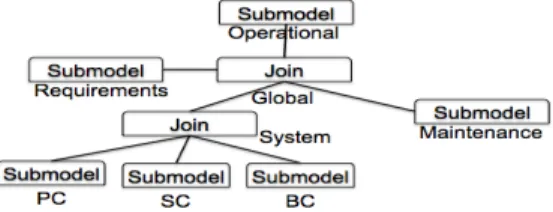
4.1 Structure of the Model
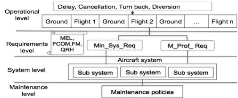
Figure 2 shows the overall structure of the model composed of four levels.
Figure 2: Overall structure of the model
Operational level: it represents the succession of periods during which the aircraft
is either flying or on ground.
Requirements level: it consists of the aggregation of the requirements from the potential contributors to the continuity of the mission. These requirements are the representation of Min_Sys_Req and M_Prof_Req. These requirements are formulated as complements of Boolean expressions, representing the different combinations leading to an operational interruption.
System level: It describes the aircraft system. The system is decomposed into
subsystems and atomic components according to its design logic or its functions. This level describes the components failure scenarios.
Maintenance level: It describes the maintenance possibilities at the various
airports involved in the mission profile. It is intended to represent the predefined maintenance policies related to the airports. This has an impact on the repair time of the system components at a given stop. The maintenance activity itself is modeled at the system level.
We build generic sub models corresponding to each of the main levels in the above structure. The composition of these sub models will form an initial model, which is to be configured and parameterized with online data in order to obtain the overall model.
The approach can be implemented using an appropriate formalism. In this paper, we consider the Stochastic Activity Networks (SANs) formalism and the associated Möbius tool [5], which provide compositional operators that are convenient to master the complexity of the model. A brief description of SANs is given in the followings.
4.2 SANs Formalism
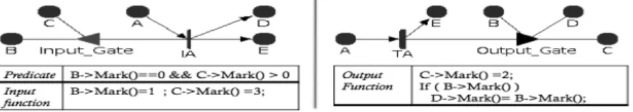
Stochastic activity networks are an extension of Petri nets (PN). SANs consist of four primitive objects: places, activities, input gates, and output gates. Activities are the equivalent of transitions in PN. They are either timed or instantaneous. Timed activities have durations and a time distribution function. Instantaneous activities represent actions that complete immediately when enabled. Input gates are used to control the enabling of activities and define the marking changes that will occur when an activity completes. Each input gate is defined with an enabling predicate and a function. Output gates are like input gates and are used to change the state of the system when an activity completes. An output gate is defined only with a function. The function defines the marking changes that occur when the activity completes. Input gates and output gates are represented graphically as triangles (see Figure 3).
An activity is enabled when the predicates of all input gates connected to the activity are true, and all places connected to incoming arcs contain tokens, i.e., have non zero markings. Once enabled, the activity samples its delay distribution function to determine the time delay before the activity fires. When the activity fires, it updates the state of the model by subtracting tokens from places connected by incoming arcs, adding tokens to places connected by outgoing arcs, and executing the functions in input and output gates.
Möbius allow the construction of composed models. Indeed, for a large system, it may be helpful to compose the overall model based on sub-models that have less complexity. This is feasible using the Join and Replicate operators. The Join operator combines several models sharing some state variables. The Replicate operator is used to create copies of models; the copies are combined into a global model. The copies may hold some state variables in common. A Join node may have other Joins, Replicates, or other sub models defined as its children.
This formalism is used to develop a case study implementing the modeling approach. The case study concerns a subsystem that controls one of the movable surfaces of the aircraft [11], referred to as CMS in the rest of the paper. The subsystem is described in the following section.
5
CMS Presentation
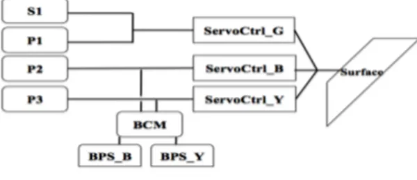
The subsystem is composed (see Figure 4) of three primary computers (P1, P2, P3), a secondary computer S1, three servo-controls (ServoCtrl_G, ServoCtrl_B and ServoCtrl_Y), a backup control module (BCM) and two backup power supplies (BPS_B and BPS_Y).
Figure 4: The subsystem
The computers are connected to the servo-controls, which move the surface. S1 and P1 are connected to the servo-control ServoCtrl_G, P2 is connected to ServoCtrl_B, and P3 is connected to ServoCtrl_Y. The connection between a computer and a servo-control form a servo-control line that can act on the surface. We have:
P1 control line (PL1): formed by the connection between P1 and ServoCtrl_G, P2 control line (PL2): formed by the connection between P2 and ServoCtrl_B, P3 control line (PL3): formed by the connection between P3 and ServoCtrl_Y, S1 control line (SL): formed by the connection between S1 and ServoCtrl_G. We have also Backup control line (BCL), which is based on BCM, BPS_B, BPS_Y, ServoCtrl_Y and ServoCtrl_B.
Initially the secondary computer S1, the backup control module BCM and the backup power supplies BPS_B and BPS_Y are inhibited. The surface is then controlled by the three primary control lines (PL1, PL2, PL3). When the three primary control lines fail, S1 is activated and the system switches to SL. If the latter also fails, BCM, BPS_B and BPS_Y are activated enabling the backup control. Therefore, three control modes can be distinguished: the primary control (PC), the secondary control (SC) and the backup control (BC). Figure 5 summarizes the control modes.
Figure 5: The control modes and associated control lines
Related Operational Requirements: According to [4]1, the failure of P2,
ServoCtrl_G, ServoCtrl_Y, ServoCtrl_B, BCM, BPS_B or BPS_Y leads to “no go” status. P1, P3 and S1 are “go if” items with “go if” conditions stated respectively at sections MMEL 27-93-01-1, MMEL 27-93-01-3 and MMEL 27-94-01-1 of the
1 [4] is actually a Master MEL(MMEL). MELs result from the completion of MMELs with
airline specific policies and are not public documents. MMELs are established by the aircraft’s manufacturer.
document. The dispatch conditions resulting from these sections are respectively (P1=ok) ! (S1=ok " P3=ok); (P3=ok) ! (S1=ok " P1=ok); (S1=ok) ! (P1=ok " P2=ok " P3 =ok)2. In the three cases, the failed component must be repaired before
the deadline of 10 days. These conditions are not dependent on any mission profile. Therefore, they are part of Min_Sys_Req.
Min_Sys_Req = ( P2 =ok " BCM =ok " BPS_B =ok " BPS_Y =ok " (P1 =ok ! (S1 =ok " P3 =ok)) " ServoCtrl_G =ok " (P3 =ok ! (S1 =ok " P1 =ok)) " ServoCtrl_Y =ok " (S1 =ok ! (P1 =ok " P3 =ok)) " ServoCtrl_B =ok ).
(1)
Using the control lines previously defined, this expression becomes: Min_Sys_Req = ( PL2 =ok " (PL1 =ok ! (PL3 =ok " SL =ok)) "
(PL3 =ok ! (PL1 =ok " SL =ok)) " BCL =ok " (SL =ok ! (PL1 =ok " PL3 =ok)) ).
(2)
There is no operational requirement related to the subsystem in the FCOM.
6
The Model
The model is the aggregation of sub models corresponding to the levels presented in section 4.1. Note that only one subsystem is considered here. Due to space limitations only the operational, requirements and system levels sub models are shown.
6.1 The System Level Sub Model
The system level sub model consists of the representation of CMS. To simplify its presentation, it is decomposed into three sub models corresponding to the control modes given in Figure 5. In all the three sub models, places representing the subsystem’s components functional state (ok or failed) are named after these components. Activities named xxx_failure represent failures events. Their enabling is conditioned by the presence of a token in place flight. Activities Maintainxx represent maintenance activities and their enabling is conditioned by the presence of a token in place Maintain. Places flight and Maintain represent respectively whether a flight is ongoing or not, and whether a maintenance period is ongoing or not. Their markings are controlled by the operational level sub model (Figure 10). For clarity purpose, some places involved in the predicate or function of the input gates are not explicitly linked to them; this is allowed by SANs.
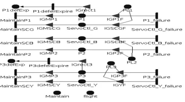
Primary control (PC) model is given in Figure 6. The transitions representing the
maintenance activities (Maintainxx) are at the left side and the failure events (xxx_failure) at the right side of the places. Their associated input gates control their firings. For example IGP1F and IGMP1 are defined as follows:
2 These are not actually the full conditions, we only consider the conditions related to the
IGP1F Predicate : P1->Mark() && flight->Mark() Function : P1->Mark()=0; PL1->Mark()=0; IGMP1 Predicate : P1->Mark()==0 && Maintain->Mark() Function : P1->Mark()=1;
if (ServoCtrl_G->Mark()) PL1->Mark()=1; P1defExp->Mark()=0;
Figure 6: PC sub model
Transition P1(3)deferExpire represents the expiration of the deadline before which the computer must be repaired after being failed. This doesn’t concern P2 since its status is “no go”. Places PLi represents the state of the lines PLi. PLi is marked when
Pi and the corresponding ServoCtrl_x in the line are marked. The markings of places Maintain and flight are used in the predicates of the input gates to enable the failure
and maintenance activities as explained above.
Secondary control (SC) is represented in Figure 7. Place S1Active represents the
activation state of S1. That is when PC fails, the instantaneous activity S1_active fires in order to mark place S1Active, representing the failover to SL. S1_inhib models the inhibition event. It fires when one of PL1, PL2 and PL3 becomes marked again, removing the token from S1Active. PL1, PL2 and PL3 are shared with the PC sub model, which controls their makings. They are only used in the predicates of IGS1A and IGS1I to express whether PC is failed or not. S1_hidden_failure and
S1_active_failure model respectively the failure events of S1 while inhibited and
activated. SL represents the functioning state of the secondary control line. It holds when S1 and ServoCtrl_G hold. ServoCtrl_G is shared with PC sub model.
Figure 7: SC sub model
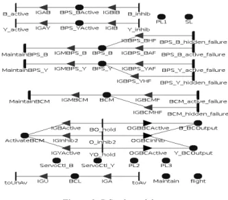
The Backup control (BC) model is depicted in Figure 8. BPS_BActive and
BPS_YActive describe the inhibition and the activation of BPS_B and BPS_Y. That is,
when PL1 and SL are inoperative, BPS_B and BPS_Y are activated to supply power to BCM. They are inhibited when PL1 or SL is operative. BPS_BActive and
BPS_YActive are updated by their associated instantaneous transitions, which fire
according to the marking of PL1 and SL as described above.
Figure 8: BC sub model
ActivateBCM represents the use of the BCM to control the surface; when none of
the primary and secondary control lines is operative and BPS_B or BPS_Y supply the BCM with electric power, the BCM is activated to attempt to control the surface via ServoCtrl_Y or ServoCtrl_B. B_YCoutput and B_BCoutput represent respectively the use of power from BPS_Y and BPS_B. BCL represents the fulfillment of the requirements on the components of the line. It is marked when BCM, BPS_B, BPS_Y,
ServoCtrl_B and ServoCtrl_Y are marked. Places Maintain and Flight are shared with
the operational level sub model; PL1, PL2, PL3, ServoCtrl_B and ServoCtrl_Y with PC sub model; and SL with SC sub model. Their marking are used as input to the BC sub model as they are involved in the activation and inhibition of the BC.
As only one subsystem is considered in this case study, the system level sub model corresponds to the composition of PC, SC and BC sub models (see Figure 11).
6.2 The Requirement Level Sub Model
Figure 9 shows the aggregation of the requirements fulfillments from the system level sub models.
Figure 9: Requirement level sub model
Place Min_Sys_Req models the requirements fulfillment. The firings of the instantaneous activities toFul and toNot update the place according to the condition
expressed in section 5 (expression (2)). Min_Sys_Req is used at the operational level. Places PL1, PL2, PL3, SL and BCL are shared with the system level sub model. M_Prof_Req is not represented here due to the fact that the subsystem has no mission profile related requirement. Nevertheless, its representation will be similar.
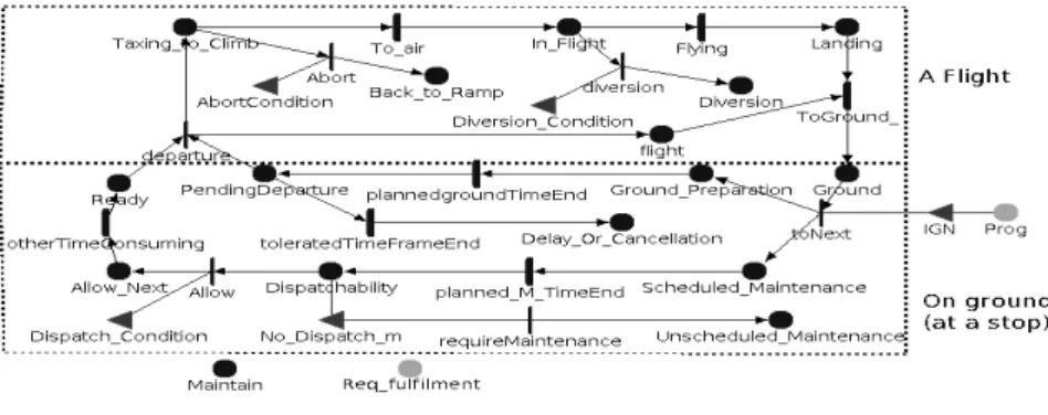
6.3 The Operational Level Sub Model
The operational level sub model is shown in Figure 10. The upper part represents a flight and the lower part represents the activities on ground at a stop. Place Maintain is shared with the system level sub model indicating the ongoing of a maintenance period. Place Req_fulfilment is an extended place representing the requirements fulfillment. It should be composed of Min_Sys_Req and M_Prof_Req, which are shared with the requirements level sub model. Since no mission profile related requirement is considered here, the share concerns only Min_Sys_Req at the requirements level. A flight is represented by three phases Taxing_to_Climb,
In_Flight and Landing. During the Taxing_to_Climb the flight can be aborted and it
can be diverted during the In_Flight phase. The input gates AbortCondition and
Diversion_Condition represent the conditions under which these interruptions can
occur (in-flight requirements fulfillment). The conditions are stated using the marking of Req_fulfilment. Place flight indicates whether a flight is ongoing or not. It is shared with the system level sub model.
Figure 10: Operational level sub model
The sub model of a ground period consists of the representation of the preparation for the next flight and the readiness for departure on time. The beginning of the preparation for the upcoming flight is represented by the marking of places
Ground_Preparation and Scheduled_Maintenance, stating that the scheduled ground
period is ongoing and the system is under scheduled maintenance (routine check for instance)3. When the scheduled maintenance is finished (activity planned_M_TimeEnd fires), the place Dispatchability then holds and the
instantaneous activity Allow can fire if the dispatch requirements, stated in the predicate of Dispatch_Condition, are fulfilled. Otherwise the instantaneous activity
requireMaintenance fires if the corrective action requires maintenance tasks (stated
by the predicate of No_Dispatch_m), place Dispatchability still holds until the corrective action succeeds (predicate of Dispatch_Condition becomes true) and the flight is allowed. In the current illustration, the dispatch requirements fulfillment consist of testing if the marking of field Min_Sys_Req in the extended place
Req_fulfilment is zero or not. Until then, the scheduled ground duration may have
elapsed (firing of activity plannedgroundTimeEnd moving the token to place
PendingDeparture) and the tolerable delay may be running out. A delay or
cancellation occurs if the tolerated time to dispatch is exceeded. The timed transition
OtherTimeConsuming represents the other activities (passengers and baggage
processing …) that may consume time, causing delay. Place Prog (at right) is an extended place representing the list of flights to be achieved. The input gate IGN indicates whether there is a next flight to achieve or not (end of the mission or not).
6.4 The Global Model
The global model results from the composition of the sub models corresponding to the four levels. It is shown in Figure 11.
Figure 11: The global model
7
Example of Results
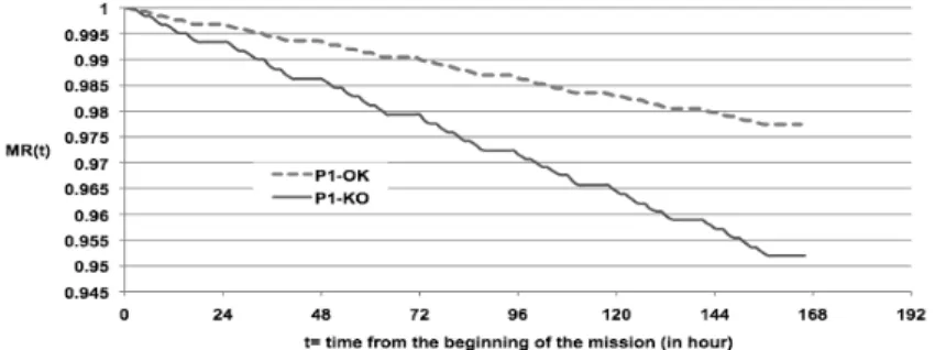
Since the model is intended to be used during the achievement of the mission, the initial markings and the parameters such as the distribution laws of the timed activities are to be set online using online data. In order to provide an example of evaluation, some values of the parameters are assumed here. We assume that all the events represented by timed activities at system level (Figures 6, 7, 8) have exponential distributions, except P1deferExpire and P3deferExpire, which have deterministic durations. The values of failure rates used for the example are between 10-4/hour and 10-6/hour. For the parameters of the operational level sub model, we consider a mission of 4 flights per day over a week. We assume that the timed activities of the operational level sub model have deterministic durations. Each flight takes 3 hours. The planned duration of a ground period is of 1.5 hour during the day and 7.5 hours at the end of the day (after 4 flights). We evaluate the mission reliability; MR(t). For illustration purposes, we consider that the in-flight requirements are the same as the dispatch requirements (Min_Sys_Req). The mission reliability MR(t) is the probability to have no tokens in places
the mission reliability considering two initial states of the primary computer P1: P1-OK (P1 is P1-OK at the starting of the mission), and P1-KO (P1 is in failure at the starting of the mission), the other components are assumed to be OK at the starting of the mission.
From the evaluation, the time from which the reliability becomes lower than a given threshold can be determined. For example, considering 0.98 as reliability threshold, one has to consider strengthening its ability to maintain after 144h in case of P1-OK and 72h in case of P1-OK. The curves also illustrate a situation where one has to decide on whether it is preferable to defer the maintenance of computer P1, knowing that there is one week remaining mission to achieve. With the assumed parameters, the reliability of the one-week mission will increase from 0.952 to 0.978 if P1 is repaired before the starting of the mission. Other examples of missions and of system reliability measures are given in [12].
8
Conclusion
This paper is aimed at developing a model that one can use to assess aircrafts operational reliability. The model is intended to be used before and during aircrafts mission achievement. A modeling approach has been developed considering aircrafts systems particularities and how the missions are achieved. The proposed model is composed of generic sub-models corresponding to components that may be involved in aircrafts operability. An illustration of the modeling approach with SANs formalism has been given using an aircraft subsystem.
The current work is focused on the construction of the initial model that will be used to assess the operational reliability. The model, however, must be updated during the achievement of the missions in order to take into account the current situation during which it will be used. The modeling approach is designed to facilitate these updates. Changes concerning the aircraft system components states and failures distributions will be taken into account in the system level sub model. Missions’ update will be managed with the operational level sub model. It is expected that the system level sub model update will rely on diagnosis and prognosis modules. Data from the flight plans will be used to configure the operational level sub model.
The model update is currently achieved manually. Methods to dynamically integrate the updates and automatically re-assess the reliability, after the occurrence of a major event, are under investigation [15].
9
References
1. A. Ahmadi and P. Soderholm, “Assessment of Operational Consequences of Aircraft Failures: Using Event Tree Analysis,” in 2008 IEEE Aerospace Conference, pp. 1-14, 2008 2. L. Saintis et. al, “Computing in-service aircraft reliability,” International Journal of
Reliability, Quality and Safety Engineering, vol. 16, n°. 02, pp. 91, 2009
3. D. Prescott and J. Andrews, “Aircraft safety modeling for time-limited dispatch,” in Annual Reliability and Maintainability Symposium, 2005. Proceedings, pp. 139-145
4. Master Minimum Equipment List, Airbus A-340-200/300, http://fsims.faa.gov/wdocs/mmel/a340-200-300%20original%2005-30-08.htm or http://fsims.faa.gov/wdocs/mmel/a340-200-300 original 05-30-08.pdf
5. D. Daly et. al, “Möbius: An extensible tool for performance and dependability modeling,” In 11th International Conference, TOOLS 2000, vol. Lecture Notes in Computer Science, pp. 332-336, Schaumnurg, IL B.R. Haverkort, H. C. Bohnenkamp, and C. U. Smith (Eds.), 2000 6. M. Sachon and E. Paté-Cornell, “Delays and safety in airline maintenance”, Reliability
Engineering & System Safety, vol. 67, n°. 3, pp. 301-309, 2000
7. N. Papakostas et. al, “An approach to operational aircraft maintenance planning,” Decision Support Systems, vol. 48, n°. 4, pp. 604-612, 2010
8. I. Mura and A. Bondavalli, “Markov Regenerative Stochastic Petri Nets to Model and Evaluate Phased Mission Systems Dependability,” IEEE Transactions on Computers, vol. 50, n°. 12, p. 1337-1351, 2001
9. S. Chew et. al, “Phased mission modelling of systems with maintenance-free operating periods using simulated Petri nets,” Reliability Engineering & System Safety, vol. 93, n°. 7, pp. 980-994, 2008
10. C. Kehren et. al, “Advanced Simulation Capabilities for Multi-Systems with AltaRica,” in Proceedings of the 22nd International System Safety Conference (ISSC), System Safety Society pp. 489-498, 2004
11. R. Bernard et. al, "Experiments in model-based safety analysis: flight controls”, First IFAC workshop on Dependable Control of Discrete Systems, Cachan, 2007, available online
http://sites.google.com/site/pierrebieber/publications/DCDS07_FlightControlsModel_RB.pdf
12. K. Tiassou, M. Kaâniche, K. Kanoun and C. Seguin, DIANA Operational Reliability — Modelling the Rudder System Using AltaRica and Stochastic Activity Networks, LAAS report No 11001
13. M. Bineid and J. P. Fielding, “Development of an aircraft systems dispatch reliability design methodology,” the aeronautical journal, 2006, vol. 110, no1108, pp. 345-352 14. A. Ramesh et. al, “Advanced methodologies for average probability calculation for
aerospace systems,” 26th international congress of the aeronautical sciences, 2008
15. K. Tiassou, K. Kanoun, M. Kaâniche, C. Seguin, and C. Papadopoulos, Operational Reliability of an Aircraft with Adaptive Missions, in Proceedings of the 13th European Workshop on Dependable Computing - EWDC '11, p. 9, 2011