HAL Id: hal-01636585
https://hal.archives-ouvertes.fr/hal-01636585
Preprint submitted on 16 Nov 2017HAL is a multi-disciplinary open access archive for the deposit and dissemination of sci-entific research documents, whether they are pub-lished or not. The documents may come from teaching and research institutions in France or abroad, or from public or private research centers.
L’archive ouverte pluridisciplinaire HAL, est destinée au dépôt et à la diffusion de documents scientifiques de niveau recherche, publiés ou non, émanant des établissements d’enseignement et de recherche français ou étrangers, des laboratoires publics ou privés.
Second Harmonic Generation in PPLN waveguides with
stitching errors
Maxim Neradovskiy, Elizaveta Neradovskaia, Dmitry Chezganov, Vladimir
Shur, Hervé Tronche, Florent Doutre, Getachew Ayenew, Pascal Baldi, Marc
de Micheli, Carlos Montes
To cite this version:
Maxim Neradovskiy, Elizaveta Neradovskaia, Dmitry Chezganov, Vladimir Shur, Hervé Tronche, et al.. Second Harmonic Generation in PPLN waveguides with stitching errors. 2017. �hal-01636585�
Second Harmonic Generation in PPLN waveguides
with stitching errors
Maxim Neradovskiy
1,2, Elizaveta Neradovskaia
1,2, Dmitry Chezganov
1,3,
Vladimir Ya. Shur
1,3, Herv´e Tronche
2, Florent Doutre
2, Getachew Ayenew
2,
Pascal Baldi
2, Marc De Micheli
2and Carlos Montes
2,∗1 Institute of Natural Sciences, Ural Federal University, Ekaterinburg, 620000, Russia 2 Universit´e Nice Cˆote d’Azur, CNRS, INΦNI, Parc Valrose, 06100 Nice, France
3 Labfer Ltd., 8 Marta str., 2-22, Ekaterinenburg 620014, Russia ∗Corresponding author: [email protected]
Depending on the chosen fabrication process, nonlinear waveguides realized in periodically oriented material such as PPLN can present different fabrication errors. In this paper we present a detailed numerical study of the impact on the nonlinear performances of one or several stitching errors occurring during the realization of the periodic domains by e-beam writing. This study shows that contrarily to what was expected, a single finite stitching error does not simply decrease the nonlinear efficiency, but splits the SH signal into a double peak spectrum, where the position of the peaks and their width at half maximum depend not only on the poling period, the total length of the grating, and the waveguide parameters but also on the amplitude and the position of the defect. The numerical results are confirmed by SHG experiments performed in PPLN waveguides obtained by Soft Proton Exchange and where the nonlinear grating was composed of one to four e-beam written 1.5 mm long PPLN sections between which important stitching error can occur. It is worthnoting that similar errors (domains merging or missing domains) can occur also in e-field poling process but they are randomly distributed along the propagation path. Therefore this study is a first attempt to take them into account to explain experimental results and indicate the steps that have to be taken to improve the quality of the components.
c
⃝ 2017 Optical Society of America
1. Introduction
Periodically poled nonlinear ferroelectric crystals are widely used to produce photonic devices such as frequency converters. Lithium Niobate (LiNbO3, LN) which offers large electro-optical and nonlinear coefficients [1] and the ability to combine periodical poling and low-loss waveguides fabrication is one of the most popular [2].
On the one hand, the effects of stitching errors have been discussed in details for the performance of waveguide Bragg gratings [3]. On the other hand, SHG in PPLN waveguides fabricated by proton exchange has been the object of previous studies [4]- [6].
Recently we have presented a detailed study of periodic domain formation by e-beam irradiation of congruent LN (CLN) containing waveguides produced by the Soft Proton Exchange (SPE) process [7]. Using this technique we have produced Periodically Poled LN (PPLN) channel SPE waveguides with different periods, an aspect ratio close to 0.4 and a PPLN section length which is an integral multiple of 1.5mm, the maximum length which can be obtained without moving the sample. Second Harmonic Generation (SHG) experiments were done using a TUNICS T100S-HP tunable laser with a fiber amplifier delivering 100 mW within the wavelength range 1535-1570 nm. For 1.5 mm-long periodically poled structures, we obtained up to 48%/W cm2 normalized nonlinear conversion efficiency at Quasi-Phase Matched (QPM) resonant wavelength of 1555 nm. Longer domain patterns, obtained by joining up to 4×1.5-mm-long structures present several finite stitching errors [8].
The aim of this article is to study numerically the impact of one or a few stitching errors on the SH spectra and to compare the numerical predictions to experimental results. Within the reversible SHG mechanism, it is expected that a stitching error corresponding to a phase shift of the order of π will yield to a severely reduced conversion efficiency especially if this error sits in the middle of the grating, as the conversion taking place in the second segment is opposite in phase with what has been created in the first one [9] [10]. The tunable laser allows us to explore the spectral domain around the QPM wavelength and the originality of our study is to experimentally and numerically show that the stitching errors not only reduce the SH response at QPM resonance, but split the SH spectrum into two or more lateral peaks while keeping the total conversion and coherence.
The influence of a phase shift sitting in the middle of the PPLN grating has been numeri-cally studied as a function of its amplitude and we show that it splits the SH spectrum into two peaks whose position and width at half maximum depends not only on the poling period, the total length of the grating, and the waveguide parameters, but also on the amplitude and the position of the defects.
By recording the SHG tuning curves on waveguides with several stitching errors, several multiple humped spectra have been obtained depending on the value of the different phase shift linking the perfect PPLN segments. In the numerical model we have considered the
dynamics when the finite stitching errors prevail over the distributed imperfections of the sample which have already been studied [11]- [15], and show that this calculation taking into account only the stitching errors can predict the main modification of the SHG spectra and therefore could also be used to explain the results obtained on devices produced by other techniques such as e-field poling where the nonlinear grating is also affected by important errors, such as domains merging or missing domains. .
2. e-beam written periodic domains with stitching errors on Soft Proton Ex-changed waveguides
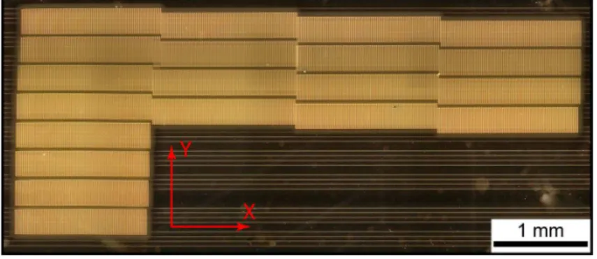
To periodically pole the SPE waveguides, we used the technique we developed for bulk MgO:LN crystals [16] based on a Scanning Electron Microscope (SEM) Auriga Crossbeam (Carl Zeiss, Germany) controlled by the electron beam lithography system Elphy Multibeam (Raith, Germany) and on the use of a 2.5-µm-thick layer of negative electron-beam resist AZ nlof 2020 Microchemicals. Periodic domain structures with four different periods ΛG (15.8, 16.0, 16.2 and 16.4 µm) and two interaction lengths L (1.5 and 4×1.5 mm) for each period have been written perpendicular to the SPE waveguides. The maximum exposition area for the SEM microscope is 1.5 × 1.5 mm, that is why it has been necessary to move the sample stage for realizing the longer structures, which obviously produce stitching errors that can be seen by visualizing the pattern written in the resist with an optical microscope (Fig. 1).
Fig. 1.Image of Y-oriented Z+ stripes domain written by electron beam irradiation
on the Z− LN surface of a sample containing channel waveguides along the X axis.
On this picture the stitching errors due to lack of precision of the sample stage are obvious. It produces an error in the periodic structure as well as a translation of the domains in the direction perpendicular to the waveguides which implies to carefully identify which periodic structures the waveguides are crossing and which allows to have some waveguides crossing only 2 poled sections and therefore to observe experimentally the effect of one stitching error.
The visualization technique of the periodical domain structures and the characterization of the planar waveguide on the Z+ surface of the wafer are presented elsewhere [8]. The domain structure revealed by Piezo Force Microscopy (PFM) presents periodical domains going through channel waveguides without any significant differences in period or duty cycle between waveguides and virgin LN, which is important for nonlinear processes when the guided mode is wider than the waveguide. The production of long domain structures in our samples present important stitching errors between writing windows, whose effects on the spectral dynamics are the object of the present article. A special interest is devoted to the waveguides supporting 2 × 1.5 mm periodic structure with a single stitching where the interpretation of the obtained results is simpler.
3. SHG dynamical equations
The SHG process, assuming the slowly varying envelope approximation, is governed by the coupled mode equations in the periodically poled waveguides possibly presenting stitching errors:
(∂t+ vF∂x+ γF + iβF∂tt) AF = iκFAF∗ASHexp(i∆Kx)exp[iδΦm(xm)] (1) (∂t+ vSH∂x + γSH + iβSH∂tt) ASH = iκSHA2Fexp(−i∆Kx)exp[iδΦm(xm)] (2) where AF and ASH are the field amplitudes (Aj = !njℓωjEj, j = F, SH) at λF and λSH (F = fundamental, SH = second harmonic) respectively; δΦm(xm) = ΣN
m=1δσm(xm)(m = 1, N) are the N integral shifts due to the eventual stitchings where the phase-shifts δσm(xm)(m = 1, N) = δΦm(xm) − δΦm−1(xm−1) (with δΦ0(x0) = 0) link the regular PPLN waveguide pieces ; κF = [2πω2
F/(kFc2)]vFχ(2)(ω; 2ω, −ω) and κSH = [4πω2
SH/(kSHc2)]vSHχ(2)(2ω; ω, ω) are the nonlinear coupling constants and the wave vec-tor mismatch between the fundamental and SH is
∆K = 2π[2(nSH− nF)/λF − 1/ΛG] (3) where 2π/ΛG is the PP grating period, βF, βSH the dispersion coefficients and γF, γSH the damping coefficients (here we will consider a lossless and dispersionless SHG process). If the difference between vF and vSH can be neglected for the nonlinear medium with a given length L and in the parametric approximation (intensity of the pump field Ap = AF remaining much higher than the intensity of the second-harmonic field ASH) we may set vF = vSH = vp and |AF|2 = |Ap|2 = const in (1)(2) to derive in the retarded frame of reference with x′ = x and τ = t − x/vp
ASH(L) = iκSH|Ap|2 sin(∆KL2 ) ∆KL 2 L exp(i∆KL 2 ). (4)
The intensity of the second-harmonic is then given by ISH(L) ∝ κ2SHIp2 " sin(∆KL 2 ) ∆KL 2 #2 L2, (5)
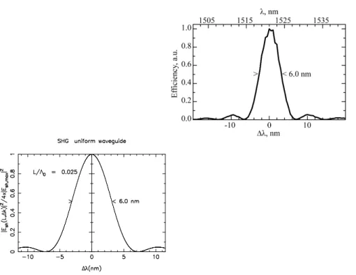
where Ip is the intensity of the pump field. Fig. 2(left) shows the spectral behaviour is-sued from the simulation of Eqs. (1)(2) for a nonlinear dimensionless length L/Λ0 = 0.025 corresponding to a 1.5 mm uniformly PP length. The characteristic length being Λ0 = 2vF/(κFAF(0))] and |AF(0)(MV/m)| = [I0
F(MW/cm2)/0.2838] 1/2
. The principal single peak measures 6.0 nm wavewidth (FWHM). The first adjacent low peaks are at 10.1 nm. The experimental spectrum for the uniform waveguide of 1.5 mm length corresponding to the numerical L/Λ0 = 0.025 of Fig. 2(left) is shown in Fig. 2(right).
4. SHG in PPLN waveguides with stitching errors
Now we are concerned with waveguides which present a stitching error in the middle of a uniform PP grating or waveguides going through several 1.5 mm-long PP sections pre-senting stitching errors at the junctions. We have recorded SHG spectra in PPLN around QPM. For a perfect PPLN sample of 1.5 mm-long the single peak SH spectrum well coin-cides with the sinc2 theoretical prediction and the measured conversion efficiency reaches up to 36%/(W.cm2). The waveguides going through several 1.5 mm-long sections present SH spectra with several peaks.
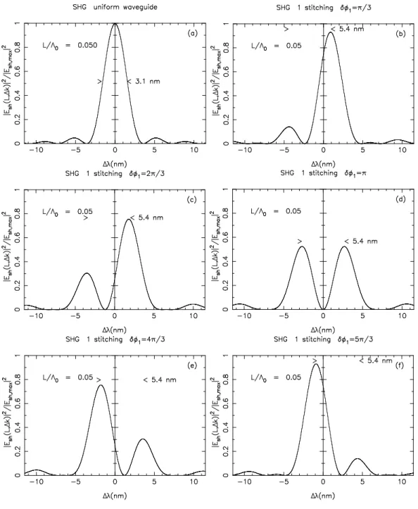
We present in Figs. 3(a-f) the evolution of the SHG spectrum of a waveguide crossing a PPLN section of length L = 2×1.5 mm [Fig. 3(a) corresponding to L/Λ0 = 0.050] as a function of the amplitude of the phase shift associated to the stitching error present in the middle of the PPLN section. As expected, for a phase shift of π, the spectrum vanishes at QPM [Fig. 3(d)] but is splited into two peaks separated by 5.4 nm, corresponding to the spectral separation between the main peak of the uniform PPLN waveguide and the first low lateral peak [cf. Fig. 3(a)]. The spectral separation is conserved for all the values of the phase shift, as well as the energy calculated from the integration of the respective spectra. This behavior, to our knowledge, has not been clearly described up to now.
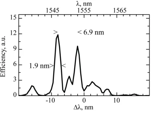
The experimental spectral efficiency of a 1-time stitched PP waveguide is plotted in Fig. 4(left) and fits quite well to the numerical spectrum we obtained for a stitching phase shift of 7π/6 [Fig. 4(right)]. In both cases the spectral separation between the two peaks measures 5.5 nm, but this best fit is obtained for a stitching phase shift which does not cor-respond to the measured domains structure. Indeed, we show in Fig. 5 a detailed view of the stitching area of the waveguide crossing two 1.5 mm long PPLN section of period 16.4µm. The domains structure is revealed using Piezo Force Microscopy (PFM), a nondestructive technique, which reveals here a stitching error of length -3µm. The corresponding phase shift is -0.37π.
The numerical spectrum for a -0.37π phase shift is plotted in Fig. 6(left) but the right peak shows a lower amplitude than the experimental one. A possible explanation of this discrepancy is the non 50-50 duty cycle composing the sample. Another plausible explanation may be the presence of additional small irregularities appearing in the periodic poling which are very difficult to detect. Indeed, as an example, we have included some very small errors accompanying the main stitching, arbitrarily distributed [e.g. in the case of the figure three errors on 0.217L, 0.364L, and 0.709L] and we remark that the spectrum moves towards the experimental shape as shows Fig. 6 (right). In the experiment the spectral response accumulates the phase shifts of such defects together with the phase shift of the principal stitching like the scenario of Figs. 3. Only the experimental detection of all the imperfections may improve the result.
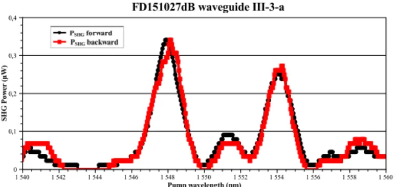
A comparison between experiment and simulation is presented in figures Fig. 7 to Fig. 9 for a 3-times stitched PP section. The SH experimental spectrum for a 4×1.5 mm-long structure containing three stitching errors is shown in Fig. 7, for forward- (black) and backward- (red) pumping directions. The similitude of the spectral shapes for the forward- and backward-directions indicates a symmetrical error distribution: the first and third stitching errors should be of the same order. The SH spectrum obtained using an OPO EKSPLA MT242 Series (1 kHz repetition rate, 3-6 ns pulse duration, less than 5 cm−1 linewidth, 150 µJ pulse energy around 1550 nm and tunable from 195 to 2600 nm) as a pump is plotted in Fig. 8. This source presents a much larger linewidth than the TUNICS laser source, but allows us to explore a much wider wavelength range to verify the absence of other SH peaks.
Numerical spectra obtained from equations (1)(2) for two symmetric stitching error dis-tributions are plotted in Fig. 9(left) for δσ1 = δσ3 = π, δσ2 = −5π/6 and in Fig. 9(right) for δσ1 = δσ3 = 7π/6, δσ2 = −π. The spectral spacing between the main peak and the third one of 6.6 nm, should be compared to the experimental spectra of Fig. 7 and Fig. 8.
5. Conclusion
In this paper we studied numerically and experimentally the influence of one or a few well localized important errors in the periodic organization of the domains of a Quasi Phase Matched waveguide on its SHG spectrum . We have shown that these errors rather than modifying the efficiency, dramatically modify the shape of the SHG spectrum. This implies that the maximum of the SHG signal does not necessarily correspond to the QPM wave-length. This also indicates that these errors have to be taken into account to explain the behavior of the experimental devices whatever technique is used to produce the periodic domains.
We did not obtained a perfect agreement between the numerical and the experimental results, which demonstrate that the model taking into account random small errors of the
domain sizes and well as important and precisely localized errors has still to be developed which will require to carefully established the respective weigths of both mechanisms.
Fig. 2. SHG tuning curves: (Left) Numerical SH spectrum for the regular PP
waveguide of dimensionless length L/Λ0 = 0.025, normalized to its maximum
0.25 × |Esh,max|2 = 6.25 × 10⁻⁴|Epump|2, as a function of the pump wavelength
de-tuning with respect to QPM ∆λ = λp− λQP M in nm. The sinc2 spectrum presents a
principal single peak, the first lateral small peaks located out 10.4 nm left and right to the central peak at ∆λ = 0. The spectral width measures 6 nm. (Right) Exper-imental SH spectrum for the regular waveguide of L = 1.5 mm length as function
of ∆λ = λp− λQP M in nm. The sinc2 spectrum presents a principal single peak of
6 nm spectral width. The first lateral small peaks are located out 10 nm left and right to the central peak at ∆λ = 0.
Fig. 3. SHG tuning curves: Scenario of the numerical evolution of the SH
spec-trum (normalized to the max of the uniform specspec-trum for L/λ0 = 0.05 i.e.
|Esh,max|2= 2.5 × 10⁻³|Epump|2 [cf. Figure (a)] for the one time stitched PP
waveg-uide for increasing phase shift stitching as a function of the pump wavelength
de-tuning with respect to QPM ∆λ = λp − λQP M in nm. The dimensionless length
L/Λ0 = 0.05 of the waveguide domain corresponds to a length L = 2×1.5 mm. As
the value of the phase shift stitching increases the whole spectrum shifts and splits into two peaks separated by 5.4 nm, corresponding to the first low lateral peak of
the regular PPLN waveguide for L/Λ0 = 0.05. As expected, for a phase shift of
π [Fig. 3(d)], the spectrum vanishes at QPM and splits into two peaks separated by 5.4 nm, corresponding to the spectral separation between the main peak of the
Fig. 4.SHG tuning curves: (Left) Spectral efficiency for the experimental 1-stitching sample as function of the pump wavelength detuning with respect to QPM ∆λ =
λp− λQP M in nm. The length of the sample measures L ≃ 2 × 1.5 mm. The spectral
separation between the two peaks measures 6.0 nm. (Right) Numerical SH spectrum for the 1-time stitched PP waveguide of phase shift 7π/6 as a function of ∆λ =
λp − λQP M in nm for a normalized length L/Λ0 = 0.05. The spectral separation
between the two peaks measures 5.5 nm.
Fig. 5.Image of Y-oriented Z+ stripes domain written by electron beam irradiation
on the Z− LN surface of a sample containing channel waveguides along the X axis.
Detail of the one stitching sample. The measured domain structure of the sample, through nondestructive PFM, is done over two periodical domain areas of regular 2π period of 16.4 µm , with one stitching error of length 3 µm. The corresponding phase shift is -0.37π The measured lengths are indicated in µm.
Fig. 6. SHG tuning curves: (Left) Numerical SH spectrum for the 1-time stitched
PP waveguide of phase shift −0.37π ≃ −11π/30 as function of ∆λ = λp− λQP M in
nm for a normalized length L/Λ0 = 0.05. For this experimentally measured stitching
length the spectrum shape moves away the experimental spectrum of Fig. 4(left). The spectral separation between the two peaks measures 5.4 nm. (Right) Numerical SH spectrum for the 1-time stitched PP waveguide of phase shift −11π/30 as a
function of ∆λ = λp−λQP M in nm (thin curve) compared to the same spectrum with
additional small perturbations of π/60 and π/90 (thick curve), arbitrarily distributed
on L, for a normalized length L/Λ0 = 0.05. The perturbed spectrum shape (in thick
dark trail) enhances the second peak, moving to the 7π/6 phase shift spectrum of the Fig. 4(left).
!"3P3-Sr#$1%&'()*+#(1,,,uHu& -. / 101 % ( 21w 34 a ! !"# !"$ !"% !"& 0*561%&'(7(8)9:1w85a
#1'&! #1'&$ #1'&& #1'&( #1'&) #1''! #1''$ #1''& #1''( #1'') #1'(!
Fig. 7. SHG tuning curve: Experimental SH spectrum: SH power (µW) vs. fon-damental wavelength (nm). for a 4×1.5 mm-long PPLN structure containing three stitchings. The spectrum for the forward right propagating pumping (black colour) nearby coincides with that for the backward left propagating pumping (red colour), proving a symmetrical phase shift stitching distribution.
Fig. 8. SHG tuning curve: SH power (µW) vs. fondamental wavelength (nm) for a 4×1.5 mm-long PPLN structure containing three stitchings using an OPO as the pump.
Fig. 9.SHG tuning curves: Numerical normalized SH power vs. ∆λ = λp−λQP M for
a 4×1.5 mm-long PPLN structure containing three stitchings (Left) of phase shifts
References
1. V. Ya. Shur, Kinetics of ferroelectric domains: Application of general approach of LnNbO3 and LiTaO3 J. Mater. Sci. 41, 199b (2006).
2. M. Bazzan and C. Sada, Optical waveguides in lithium niobate: Recent developments and applications Appl. Phys. Rev. 2, 040603 (2015).
3. S. Zamek, M. Khajavikhan, D.T.H. Tan, M. Ayache, B. Slutsky, and Y. Fainman, Effects of Lithographic Stitching Errors on the Performance of Waveguide Bragg Gratings 2011, arXiv:1110.6867v1 [physics.optics].
4. K.R. Parameswaran, R.K. Route, J.R. Kurz, R.V. Roussev, M.M. Fejer, and M. Fu-jimura, Highly efficient second-harmonic generation in buried waveguides formed by an-nealed and reverse proton exchange in periodically poled lithium niobate, Opt.Lett. 27 179-181 (2002).
5. T. Suhara and M. Fujimura, Numerical analysis of ultrashort pulse wavelength conversion characteristics of LiNbO3 waveguide nonlinearoptic devices in ”Waveguide Nonlinear-Optic Devices”, Springer, New York, (2003).
6. S. Tanzilli, P. Baldi, M.P. De Micheli and D.B. Ostrowsky ; H. De Riedmatten, W. Tittel, H. Zbinden and N. Gisin, Highly Efficient Photon-Pair Source Using a Periodically Poled Lithium Niobate Waveguide Electron. Lett. 37, 26-28 (2001).
7. L. Chanvillard, P. Aschieri, P. Baldi, D.B. Ostrowsky and M. De Micheli; L. Huang and D.J. Bamford, Soft Proton Exchange on PPLN: a simple waveguide fabrication process for highly efficient nonlinear interactions Appl. Phys. Lett. 76, 1089 (2000).
8. D.S. Chezganov, E.O. Vlasov, M.M. Neradowskiy, L.V. Gimadeeva, E.A. Neradowskaya, M.A. Chuvakova, H. Tronche, F. Doutre, P. Baldi, M.P. De Micheli, and V.Ya. Shur, Periodic domain pattering by electron beam of proton exchanged waveguides in lithium niobate Appl. Phys. Lett. 108, 192903 (2016).
9. K. Gallo and G. Assanto, All-optical diode based on second-harmonic generation in an asymmetric waveguide, J. Opt. Soc. Am. B, 16, 267-269 (1999).
10. S. H. H. Subramani, K. Karthikeyan, A. Mirunalini, R. K. Prasath, S. Boomadevi, and K. Pandiyan, Analysis of a phase reversal quasi-phase matching device for the dual peak second harmonic response, J. Opt. 15, 055205-1-6 (2013).
11. F.R. Nash, G.D. Boyd, M. Sargent III, and P.M. Bridenbaugh, Effect of Optical Inhomo-geneities on Phase Matching in Nonlinear Crystals, F. R. Nash, G. D. Boyd, M. Sargent III, and P. M. Bridenbaugh, J. Appl. Phys. 41, 2564-2576 (1970).
12. E.J. Lim, S. Matsumoto, and M.M. Fejer, Appl. Phys. Noncritical phase matching for guidedwave frequency conversion, Appl. Phys. Lett. 57, 2294-2296 (1990).
13. S. Helmfrid, G. Arvidson, and J. Webj¨orn, Influence of various imperfections on the con-version efficiency of second-harmonic generation in quasi-phase-matching lithium niobate waveguides, J. Opt. Soc. Am. B 10, 222-229 (1992).
14. M.M. Fejer, G.A. Magel, D.H. Jundt, and R.L. Byer, Quasi-Phase-Matched Second Har-monic Generation: Tuning and Tolerances, IEEE J. Quantum. Electron. 28, 2631-2653 (1992).
15. M.L. Bortz, S.J. Field, M.M. Fejer, D.W. Nam, R.G. Waarts, and D.F. Welch, Noncrit-ical quasi-phase-matching second harmonic generation in an annealed proton-exchanged LiNbO3 waveguide, IEEE Trans. Quantum Electron. 28, 2953-2960 (1994).
16. Y. Shur, D. S. Chezganov, A. R. Akhmatkhanov, and D. K. Kuznetsov, Domain pattern-ing by electron beam of MgO doped lithium niobate covered by resist, Appl. Phys. Lett. 106, 232902 (2015).