HAL Id: hal-01780401
https://hal.archives-ouvertes.fr/hal-01780401
Submitted on 27 Apr 2018
HAL is a multi-disciplinary open access
archive for the deposit and dissemination of
sci-entific research documents, whether they are
pub-lished or not. The documents may come from
teaching and research institutions in France or
abroad, or from public or private research centers.
L’archive ouverte pluridisciplinaire HAL, est
destinée au dépôt et à la diffusion de documents
scientifiques de niveau recherche, publiés ou non,
émanant des établissements d’enseignement et de
recherche français ou étrangers, des laboratoires
publics ou privés.
Stress corrosion crack initiation of Zircaloy-4 cladding
tubes in an iodine vapor environment during creep,
relaxation, and constant strain rate tests
Tristan Jezequel, Quentin Auzoux, David Le Boulch, Maxime Bono, Eric
Andrieu, Christine Blanc, Valérie Chabretou, Nathanael Mozzani, Martin
Rautenberg
To cite this version:
Tristan Jezequel, Quentin Auzoux, David Le Boulch, Maxime Bono, Eric Andrieu, et al.. Stress
corrosion crack initiation of Zircaloy-4 cladding tubes in an iodine vapor environment during creep,
relaxation, and constant strain rate tests. Journal of Nuclear Materials, Elsevier, 2018, vol. 499, pp.
641-651. �10.1016/j.jnucmat.2017.07.014�. �hal-01780401�
Open Archive TOULOUSE Archive Ouverte (OATAO)
OATAO is an open access repository that collects the work of Toulouse researchers and
makes it freely available over the web where possible.
This is an author-deposited version published in :
http://oatao.univ-toulouse.fr/
Eprints ID : 19734
To link to this article : DOI:
10.1016/j.jnucmat.2017.07.014
URL :
http://dx.doi.org/10.1016/j.jnucmat.2017.07.014
To cite this version :
Jezequel, Tristan and Auzoux, Quentin and Le
Boulch, David and Bono, Maxime and Andrieu, Eric and Blanc,
Christine and Chabretou, Valérie and Mozzani, Nathanael and
Rautenberg, Martin Stress corrosion crack initiation of Zircaloy-4
cladding tubes in an iodine vapor environment during creep,
relaxation, and constant strain rate tests. (2018) Journal of Nuclear
Materials, vol. 499. pp. 641-651. ISSN 0022-3115
Any correspondence concerning this service should be sent to the repository
administrator:
staff-oatao@listes-diff.inp-toulouse.fr
Stress corrosion crack initiation of Zircaloy-4 cladding tubes in an
iodine vapor environment during creep, relaxation, and constant
strain rate tests
T. Jezequel
a,b, Q. Auzoux
a, D. Le Boulch
a,*, M. Bono
a, E. Andrieu
b, C. Blanc
b,
V. Chabretou
c, N. Mozzani
d, M. Rautenberg
eaDen-Service d'Etude des Mat!eriaux Irradi!es (SEMI), CEA, Universit!e Paris-Saclay, 91191 Gif-sur-Yvette, France bCIRIMAT, Universit!e de Toulouse, CNRS, INPT, UPS, ENSIACET, 4 all!ee Emile Monso, CS 44362, 31030 Toulouse, France cAREVA NP, 10 rue Juliette R!ecamier, 69456 Lyon, France
dEDF R&D, Site des Renardi"eres, 77818 Moret-sur-Loing, France eEDF Septen, Avenue Antoine Dutrievoz, 69100 Villeurbanne, France
h i g h l i g h t s
! The experimental results showed that the apparent threshold hoop stress for I-SCC was found to be independent of the test temperature.
! A model for the time-to-failure of a cladding tube was developed usingfinite element simulations of the viscoplastic mechanical behavior of the material and a modified Kachanov's damage growth model.
! The times-to-failure predicted by this model are consistent with the experimental data.
a b s t r a c t
During accidental power transient conditions with Pellet Cladding Interaction (PCI), the synergistic effect of the stress and strain imposed on the cladding by thermal expansion of the fuel, and corrosion by iodine released as a fission product, may lead to cladding failure by Stress Corrosion Cracking (SCC). In this study, internal pressure tests were conducted on unirradiated cold-worked stress-relieved Zircaloy-4 cladding tubes in an iodine vapor environment. The goal was to investigate the influence of loading type (constant pressure tests, constant circumferential strain rate tests, or constant circumferential strain tests) and test temperature (320, 350, or 380"C) on iodine-induced stress corrosion cracking (I-SCC). The
experimental results obtained with different loading types were consistent with each other. The apparent threshold hoop stress for I-SCC was found to be independent of the test temperature. SEM micrographs of the tested samples showed many pits distributed over the inner surface, which tended to coalesce into large pits in which a microcrack could initiate. A model for the time-to-failure of a cladding tube was developed using finite element simulations of the viscoplastic mechanical behavior of the material and a modified Kachanov's damage growth model. The times-to-failure predicted by this model are consistent with the experimental data.
1. Introduction
The fuel rods of a pressurized water nuclear reactor consist of fuel pellets stacked inside cladding tubes, which act as the first of several barriers that contain the fuel and prevent the dissemination
of fission products. During the fabrication of the rods, there is initially a small radial gap between the pellet and the cladding. In the reactor, the gap closes as the result of cladding diameter decrease due to irradiation creep and pellet diameter increase due to swelling. This phenomenon leads to the Pellet-Cladding Inter-action (PCI). Once this occurs, the synergistic effect of the tensile hoop stress and strain imposed on the cladding by the thermal expansion of the fuel during accidental power transient conditions
* Corresponding author.
E-mail address:david.leboulch@cea.fr(D. Le Boulch).
and corrosion by released fission products may lead to cladding failure by Stress Corrosion Cracking (SCC)[1e4]. Iodine, one of the fission products, is known to be a causative agent of SCC, referred to as I-SCC[2,5,6]. A number of researchers have investigated I-SCC of zirconium-alloy cladding, notably with creep tests in an iodine vapor environment[7e14].
During a power transient, the loading path on the cladding is quite complex and consists of two phases. As the pellet expands due to its temperature increase, the stress and strain in the cladding increase rapidly, and once the temperature and pellet diameter have stabilized, the stress in the cladding relaxes as its total strain remains constant[5,15,16]. In that context, the primary goal of the present work was to study the response of the cladding in an iodine vapor environment with several different loading modes, including constant internal pressure tests (creep), constant hoop strain rate tests, and constant hoop strain tests (relaxation). Tests were per-formed with an experimental device that monitored and measured the strain and stress in the sample. After the tests, specimens were examined by SEM to study the inner surface of the tube, and to characterize the fracture mode on the crack faces. A model for cladding failure via I-SCC was computed based on the results of the creep and relaxation tests using a viscoplastic material behavior law and a progressive damage law.
2. Material and experimental procedure
The material used in this study was cold-worked stress-relieved (CWSR) Zircaloy-4 cladding. It was commercially produced and supplied by AREVA NP. The tubes had an outer diameter of 9.52 mm and an inner diameter of 8.36 mm. The chemical composition is given inTable 1.
As-received specimens were used for time-to-failure tests in order to investigate crack initiation on a Zircaloy-4 cladding surface in an iodine vapor environment. Cladding was cut into 90 mm-long tubes. The inner surface was as-received, not polished, with roughness characteristics as follows: Ra ¼ 0.2
m
m, Rp ¼ 1.6m
m, and Rq ¼ 0.3m
m. An internal pressure test was devised to simulate I-SCC conditions on the sample. A zirconium crucible, which con-tained solid iodine, was inserted into the Zircaloy-4 tube, and the specimen was set up on the test device (Fig. 1). The specimen was put inside a furnace, and after reaching the test temperature, it was pressurized with argon of purity 99.995%. As the temperature increased, the iodine inside the crucible sublimated and passed through holes in the crucible into the cladding tube. The iodine used in this study had a purity of 99.99%. For each test, 75 ± 5 mg of solid iodine were used, so the equivalent iodine concentration in the sample was 3 mg/cm2or 15 mg/cm3. This concentration is in the range of iodine surface concentrations that lead to saturated effect of the iodine content on I-SCC susceptibility of Zircaloy-4[7]. Such a high iodine concentration is not meant to be representative of the fuel rod inner atmosphere. The testing device could reach a pressure of 1000 bar and a temperature of 600"C, that both could be controlled independently. A laser passing through the furnace permitted the measurement of the specimen's outer diameter throughout the test, from which the applied pressure could be regulated in order to control the hoop strain. The control system monitored and recorded the sample temperature, internal pres-sure, sample diameter, and elapsed time. The following expressionswere used to evaluate the mean hoop strain and hoop stress in the sample[17].
εmacro¼ change in external diameter
initial external diameter (1)
s
¼applied pressure $ ½ðexternal diameter þ internal diameterÞ=2)2 $ cladding thickness
(2)
The strain-to-failures were measured by laser axial profilome-tries of the samples, after the tests.
To minimize oxidation of the outer surface of the sample, argon gas flowed into the furnace throughout the test. The ends of the sample were sealed with stainless steel tube fittings, one of which contained an inlet for the pressurized argon. The connectors had been pre-oxidized to minimize any potential reaction between the stainless steel and the iodine vapor. The test was stopped either when the sample failed or after 72 h. After the test, the specimen was examined using an optical microscope (OM) and a scanning electron microscope (SEM) to analyze the inner surface and the fracture area on the crack face.
3. Experimental results
3.1. Pitting and cracking
In I-SCC tests in iodine vapor, numerous pits are found all over the inner surface of the zirconium specimens. This phenomenon has been commonly observed during the corrosion of bulk zirco-nium by iodine vapor[5,13,18]. Pits can be isolated or coalesced into large pit clusters. In this study, the size and coalescence of the pits varied from one specimen to another, without any apparent rela-tion to the loading mode, temperature, or stress and strain levels. Isolated pits reached up to 5 microns in diameter, and pit clusters could reach several tens of microns. The pit depth was estimated by interferometric (Fig. 2) and cross-section measurements and did not exceed 6 microns, even in the case of large pit clusters. Thus, pitting was mostly a surface phenomenon, which spread progres-sively all over the inner surface but did not penetrate into the material. Microcracks were seen in some pits, indicating that pit clusters could be preferential initiation sites for microcracks. One goal of this study was to examine how pits evolved and when they coalesced enough to initiate microcracks.
Table 1
Chemical composition of Zircaloy-4 specimens (wt. %).
Alloying elements Fe Cr Sn O H, ppm Zr
Zircaloy-4 0.22 0.12 1.31 0.12 4 Bal.
Pitting kinetics was studied by SEM examinations of Zircaloy-4 cladding tubes pressurized at 10 bar. Exposures to the aggressive environment ranged from 30 min to 72 h. During each test, the sample was heated to 320, 350, or 380"C, which took approxi-mately 45 min. The development of pits during the exposure was studied in terms of pit distribution, density, and size. SEM micro-graphs indicated that pits developed in three stages (Fig. 3): a first stage corresponding to an incubation period (less than 45 min) when iodine vapor does not lead to visible corrosion of the alloy, a second stage corresponding to a transitory period (beginning before 45 min and developing during approximately 24 h) with nucleation, growth and coalescence of pits, and finally a third stage of generalized pitting, in which the whole surface becomes covered with numerous pits.
Those results showed that pitting began rapidly, even before the sample reached its final temperature. The ratio of corroded surface to unaffected surface increased with the duration of exposure to the iodine. However, it was observed that pit size changed very little with exposure time, but the degree of pit coalescence increased with time.
During the internal pressure tests in an iodine vapor environ-ment, the Zircaloy-4 tubes could fail either by SCC or due to the mechanical loading only. If the control monitor indicated a loss of pressure in the sample, which meant it had failed, it was later examined by OM and SEM to confirm the presence of a crack on the inner surface and to examine the crack face.Fig. 4 shows SEM micrographs of a crack face after an I-SCC test, which reveals a region of brittle cracking surrounded by a zone exhibiting many dimples that indicate ductile tearing. The region of brittle cracking corresponds to the propagation of a stress corrosion crack, and the surrounding ductile tearing region corresponds to the final failure of the tube due to the increased local stress after the stress corro-sion crack had penetrated a certain distance into the material
[9,13,19,20]. Many pits are evident on the part of the crack face near the inner surface of the tube (Fig. 5). For most of the failed samples, a small pinhole type crack was visible on the external surface of the tube, as shown inFig. 6. The pinhole was often surrounded by a
yellow halo. This type of pinhole failure is typical of I-SCC[19]. Other samples exhibited failure due to mechanical stress without any indication of a brittle stress corrosion crack, notably for high stress levels. For these samples, the external surface of the tube exhibited a much larger, axially oriented crack that was often located on a ballooned region. For these cases, SEM examination was used to determine whether the failure occurred due to I-SCC or due to pure mechanical ductile tearing only.
3.2. Effect of the loading mode on I-SCC at 350"C
The effects of several different types of loading modes were investigated. For each type of loading mode, the test was stopped either when failure occurred or after 72 h had elapsed. In a creep test, the internal pressure of the sample was increased at a rate of 1 bar/s up to the final pressure. The pressure was then held constant until the end of the test. In a strain rate test, the sample was loaded at a constant strain rate of either 3 $ 10*6s*1, 5 $ 10*6s*1, or 1 $ 10*5s*1until failure occurred. In a relaxation test, the sample was loaded at a constant strain rate (10*5s*1) up to a certain hoop strain (either 0.6%, 0.8%, 1.0%, 1.2%, or 1.4%). It was then maintained at that hoop strain, as the stress relaxed, until the end of the test. This kind of test exhibited a great deal of scatter in the data, as shown inFig. 7. For identical test conditions, the time-to-failure could be as little as 1 h, or the sample might not failure after 72 h, at which point the test was stopped.
The times-to-failure obtained experimentally are given in
Table 2. This degree of experimental scatter is common in SCC experimental campaigns.
Fig. 8shows the relationship between measured time-to-failure and hoop stress at failure for unirradiated Zircaloy-4 specimens for I-SCC tests at 350"C under various loading conditions. For each type of loading mode, as the stress increased, time-to-failure decreased and total diametrical strain increased. For constant pressure creep tests, the maximum hoop stress at which I-SCC was observed was around 400 MPa. Above that value, failure did not occur via I-SCC. Instead, the sample experienced thermal creep until it burst due to the mechanical load. However, strain rate tests led to sample failure by I-SCC at higher stress levels, up to 500 MPa. The data for the three types of tests are presented in a different manner inFig. 9. For the samples that failed, each point on the graph represents the hoop stress and hoop strain at failure. A sample that did not fail after 72 h is indicated by an open symbol, and for these samples, the point represents hoop stress and hoop strain of the sample when the test was stopped after 72 h. Both
Figs. 8 and 9indicate that the lower threshold stress (
s
0), below which failure by I-SCC did not occur, was around 240 MPa for all of the loading modes.3.3. Influence of test temperature
The influence of temperature was also investigated using creep tests at 320, 350 and 380"C. The objective was to study how the temperature could influence both the material behavior under high pressure loading and the chemical reaction between the zirconium specimen and its aggressive environment. As indicated inFig. 10
andFig. 11, for the same stress level, an increase in temperature led to a decrease in the time-to-failure and an increase in the strain-at-failure. The threshold stress,
s
0, appeared to be approximately 240 MPa regardless of the temperature.As shown inFig. 11, the minimum strain-at-failure was about 1% at 380"C, around 0.65% at 350"C, and 0.4% at 320"C. This effect is believed to be mainly due to a higher activation energy for creep than for I-SCC because the effect of temperature on the crack faces and on pitting was not significant.
Fig. 2. Measured Zircaloy-4 surface pitting after exposure to an iodine vapor envi-ronment. TD stands for transversal direction; LD stands for longitudinal direction.
4. I-SCC modeling
4.1. Material viscoplastic behavior
In order to predict the initiation of a stress corrosion crack, the stress at the inner surface of the sample must be known, which requires an accurate model for the viscoplastic behavior of the material. The present model for the viscoplastic behavior of the material was established by performing finite element (FE) simu-lations of the internal pressure tests presented above. The FE
simulations were performed with the Mistral module of the finite element software Cast3M[21], in a 2D radial-tangential plane, us-ing an anisotropic viscoplastic law for unirradiated Zircaloy-4 at 320, 350 and 380"C in the stress range between 0 and 600 MPa. The finite element mesh is made of linear square elements with 4 nodes and is shown inFig. 12.
The internal pressure is simulated by radial nodal forces applied at the inner wall of the cladding. The internal pressure also creates an axial resultant force F on the end caps of the specimen, whose value is a function of the internal pressure P and the inner radius Ri
Fig. 3. Pitting kinetics on an unirradiated Zircaloy-4 specimen in an iodine vapor environment.
of the cladding:
F ¼ P:
p
:R2i (3)In order to take into account the axial resultant force F, the FE simulations were performed using a generalized plane strain analysis. In this type of analysis, an axial load is applied to the mesh. In the example shown inFig. 12, the mesh represents 1/16 of the cladding (the simulated angle is
q
¼p
/8), so the force applied in the calculations (Fapplied) is equal to F/16 (Eq.(4)).Fapplied¼ F$
q
2:
p
: (4)The geometry of the mesh was recomputed after each step of calculation. In particular, the radial nodal forces applied at the inner wall of the cladding and the axial load were recomputed after each step. As a consequence, the hoop stress defined in Eq.(2)represents the initial value.
In the model, the total strain is defined as the sum of an isotropic elastic strain and an anisotropic viscoplastic strain that accounts for the thermal creep. The model for the anisotropic viscoplastic strain component has the form identified by Soniak [22] for stress-relieved Zircaloy-4. As shown in Eq. (5), the viscoplastic strain rate (_ε) is a function of the current strain (ε) the initial and steady creep rates (respectively vp0and vs0) and the transition strain be-tween initial and steady creep rates (ε0).
_ε ¼ vs0þ ! " vp0* vs0# exp $ *ε ε0 %& (5)
The parameters, ε0, vp0and vs0, are functions of the temperature, T, and hoop stress,
s
, as indicated in equations(6)e(8).ε0¼ ε01exp$*ε02 T % thðε03
s
Þ (6) vp0¼ vp01exp $*v p02 T % sh" vp03s
# (7) vs0¼ vs01exp$*vs02 T % shðvs03s
Þ (8)A comparison of the measured and simulated strain-versus-time curves is shown inFig. 13. The simulations used the parame-ters determined from the creep tests described above. The figure shows that the simulations match the experimental results fairly well for the creep tests carried out at temperatures 350"C for stress levels ranging from 250 to 400 MPa.
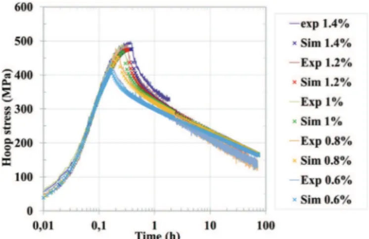
The simulations were also compared to data from relaxation tests, in which the sample was loaded at a constant hoop strain rate of 10*5s*1up to a certain strain (either 0.6%, 0.8%, 1.0%, 1.2%, or 1.4% hoop strain). The sample was then held at that particular hoop strain as the material relaxed, meaning that the control system reduced the internal pressure in order to maintain a constant sample diameter.Fig. 14shows the good agreement between the simulations and the experimental results for the relaxation tests performed at 350 "C. The model underestimates the maximum stress by about 30 MPa (6%) for each strain level.
4.2. Damage model
As mentioned before, cladding damage is believed to begin with surface pitting, which is followed by microcracking. The SCC failure process is often considered to consist of two phases: a crack initi-ation phase and a crack propaginiti-ation phase[1]. The initiation phase
Fig. 5. SEM micrographs of the cladding crack face after a creep test in iodine vapor,
magnification of the red boxed zone inFig. 4. Some pits can be observed at the entry of
the I-SCC crack. This is the result of pitting after the I-SCC crack initiated and propa-gated because this pits were not connected to the inner wall of the sample before the crack initiated. (For interpretation of the references to colour in this figure legend, the reader is referred to the web version of this article.)
is believed to occur relatively slowly, and once the crack has initi-ated, its propagation and the subsequent failure of the cladding occur relatively quickly. Studies of crack propagation rates on pre-cracked specimens support this hypothesis[1,23,24]. Because the
crack initiation time is significantly greater than the propagation time, the total time-to-failure can be considered to be approxi-mately equal to the initiation time. The damage model used in the present study is based on this assumption.
Fig. 6. Zircaloy-4 tube after an I-SCC test showing a pinhole crack on the external surface (left). Magnification of a pinhole crack obtained on another sample (right).
Fig. 7. Hoop stress versus hoop strain for relaxation tests on Zircaloy-4 specimens in an iodine vapor environment at 350"C.
Table 2
Results of the relaxation tests, performed at different hoop strains, in an iodine environment at 350"C.
Final Hoop strain Time-to-failure for sample 1 Time-to-failure for sample 2 Time-to-failure for sample 3
0,6% Non failure after 72 h Non failure after 72 h e
0,8% Non failure after 72 h 1,5 h e
1,0% 0,3 h 0,5 h e
1,2% Non failure after 72 h Non failure after 72 h 1,5 h
The model uses an internal scalar variable to represent material damage, following the method developed by Kachanov[25], who examined the fracturing process due to cavity nucleation and growth during creep. In the present study, an internal scalar
Fig. 8. Hoop stress at failure versus measured time-to-failure for unirradiated
Zircaloy-4 specimens in an iodine vapor environment at 350"C (an open symbol indicates that
the sample did not fail).
Fig. 9. Hoop stress and strain at failure or at the end of the test for unirradiated
Zircaloy-4 specimens in an iodine vapor environment at 350"C (an open symbol
in-dicates that the sample did not fail).
Fig. 10. Measured time-to-failure versus hoop stress for unirradiated Zircaloy-4
specimens in an iodine environment at 320"C, 350"C and 380"C for creep tests
(an open symbol indicates that the sample did not fail).
Fig. 11. Experimentally measured hoop stress and strain at failure for creep tests at 320"C, 350"C and 380"C (an open symbol indicates that the sample did not fail).
Fig. 12. 2D finite element mesh with the boundary conditions and the pressure applied at the inner wall of the cladding.
Fig. 13. Comparison between simulated and experimental behavior of stress relieved
Zircaloy-4 for creep tests at 350"C in an iodine vapor environment for stresses ranging
variable, D, is used to represent material damage corresponding to the initiation of a crack via I-SCC. The model considers the gradual initiation of a microcrack at the inner surface of the cladding. In the finite element model, the thickness of the cladding is divided into a number of elements, which allows the local hoop stress (
s
qq) to becalculated as a function of radius through the thickness of the cladding using the viscoplastic material behavior model described above. Because the corrosive iodine initially acts only on the inner surface, the innermost element is the most important in the anal-ysis. The damage of this element by I-SCC is characterized by the scalar D, whose value ranges from 0 to 1. Initially, before any damage has occurred, D ¼ 0. As time progresses and damage occurs via I-SCC at the inner surface, D increases. When D reaches a value of 1, the inner surface of the cladding is assumed to have been sufficiently damaged for a crack to initiate. As discussed above, the cladding is assumed to fail shortly thereafter.
The size of the elements of the mesh presented inFig. 12 is sufficiently fine that the calculated values for the stress and the strain do not change if a finer mesh is used. As a consequence, the evaluation of the damage D is independent of the mesh used in the calculations.
The evolution with time of the scalar damage variable, D, is given by Eq.(9). Note that in order to use the damage model either in post-data processing or coupled with the viscoplastic Zircaloy-4 behavior in FE simulations, an effective stress,
s
/(1-D), is introduced. dD dt ¼ As
1 * D*s
0 n (9)A and n are parameters that are used to fit the model to the
experimentally measured times-to-failure. Recall that the time-to-failure and the crack initiation time are approximately equal. This model gives priority to stress and time as already pointed out by Videm[15]. The parameter A is a function of temperature, as seen in Eq.(10). A ¼ A0exp $*T0 T % (10)
The damage variable D and the time to failure are determined by solving Eq.(9)in post-treatment of the calculations, where
s
is the average hoop stress through the cladding thickness, which is given by Eq.(2). The damage law parameters, A0, T0, n, were determinedby fitting the calculated times-to-failure to the experimental results of I-SCC creep tests carried out at temperatures of 320, 350 and 380"C for stress levels between 250 and 400 MPa. The threshold stress,
s
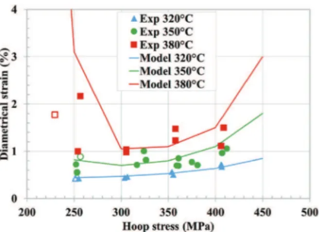
0, was approximately equal to 240 MPa for all of the tem-peratures tested, so this value was used in the model. Note that the temperature effect on I-SCC damage is taken into account by the activation temperature, T0.Fig. 15 shows the good agreement between the simulations, which use the viscoplastic constitutive equations and Kachanov's damage law discussed above, and the experimental results of creep tests at 320, 350 and 380"C. In addition to predicting the time-to-failure, the model can also predict the strain-at-time-to-failure, as seen in
Fig. 16.
Two parameters sets were identified: a first set, a “best fit” approach (A0¼ 1.59 10*16Pa*n.s*1, T0¼ 12000 K, n ¼ 2.4), in which the model gave an average fit of the experimental results, and a second set, a conservative approach (A0 ¼ 3.24 10*16 Pa*n.s*1, T0¼ 12000 K, n ¼ 2.4), in which the model delimited a failure and a non-failure domain.Fig. 17 illustrates the two approaches more clearly using a graph of the average hoop stress in the cladding versus the experimentally measured times-to-failure for the con-stant pressure tests performed at 350"C. The green points on the graph are the experimentally measured values. The green curve was obtained by performing a “best-fit” to the experimental data points to determine the damage law parameters. The red curve corresponds to the conservative approach, and it was fixed such that it fell below and to the left of all of the experimental data points.
Having established the model based on data from constant pressure creep tests, it can be further validated by comparing the predictions with data from the relaxation tests shown inFig. 7.
Fig. 18presents the simulated and the measured times-to-failure versus hoop strain at failure for the relaxation tests performed at 350"C. Recall that in a relaxation test, the sample is pressurized at a constant hoop strain rate of 10*5s*1up to a certain hoop strain, and it is then held at that strain as the material relaxes. This type of test presents a great deal of scatter in the experimentally measured times-to-failure, as evidenced inFigs. 7 and 18.
The green curve inFig. 18represents the times-to-failure pre-dicted by the best-fit model, and the red curve represents the conservative model. In the case of the “best-fit model”, the damage model overestimates the time-to-failure for these relaxation tests, but the “conservative model” predicts the experimentally measured times-to-failure reasonably well.
Fig. 14. Comparison between simulated and experimental behavior of Zircaloy-4 for
relaxation tests at 350"C in an iodine environment for hoop strains ranging from 0.6%
to 1.4%.
Fig. 15. Comparison between experimental data and calculated times-to-failure for
5. Discussion
5.1. Validity of the model
The damage law proposed in the present study depends only on stress and time (Eq.(9)). Provided that the creep strain are low,
predicted time-to-failure of creep tests are consequently not sen-sitive to the viscoplastic mechanical behavior of the material. On the contrary, predicted time-to-failure of relaxation tests depend on the stress evolutions resulting from the calculation of the vis-coplastic response to the imposed strain evolutions. In the present case, the maximum stress is slightly underestimated by the model (Fig. 14). Time-to-failure of relaxation tests may consequently be overestimated even though the “conservative damage model” was used. Accordingly, the “conservative model” is conservative when applied to creep tests, but for two of the relaxation tests, the times-to-failure are overestimated (Fig. 18). Improving the viscoplastic behavior modelling should therefore improve the conservatism of the proposed approach when applied to relaxation tests.
In addition to predicting the time-to-failure, the model can also predict the strain-at-failure. Noticeable is the fact that the model reproduces the strain-at-failure evolution with stress and temper-ature (Fig. 16). The model parameters were determined from data from creep tests, but it should be noted that relaxation tests are actually a better representation of the loading of the cladding during a power transient in a reactor, in which the thermal expansion of the fuel pellet is imposed on the cladding. Once the temperature of the fuel pellet has stabilized, its diameter remains constant and the cladding experiences a relaxation phase, in which the stress decreases. However, creep tests are simpler than relax-ation tests, and their interpretrelax-ation is more straightforward because they are performed at constant stress. Thus, the creep tests permitted the identification of the model parameters, both for the viscoplastic behavior law and Kachanov's damage law. The model and the parameters identified from these tests were found to be in relatively good agreement with the relaxation tests, which vali-dates the suitability of the damage model.
5.2. Comparison with other research
The results of the present work are consistent with those of previous studies that performed creep tests at 350 "C in iodine vapor, as shown inFig. 19. For each of the studies, nearly identical values were found for the threshold stress below which no I-SCC failure occurred. In the present study and in Park's study[13], the value of the threshold stress is approximately 240 MPa, and in the study performed by Rouillon (published in Ref.[23]), the value is approximately 290 MPa.
In the current research, additional experiments were performed using identical test conditions on CWSR Zircaloy-4 cladding sam-ples from a different production batch. The results obtained with that different production batch are presented inFig. 19and denoted “batch B”. This set of creep tests at 350"C revealed a threshold stress around 290 MPa. This same material batch was used in studies performed by Magnusson[27]in I-SCC tests in iodine vapor using an expanding mandrel technique at an iodine partial pressure of 60 Pa, which corresponds to a saturated effect of the iodine partial pressure on I-SCC susceptibility[28]. They found an I-SCC threshold stress of approximately 300 MPa over the temperature range 320"Ce380"C. It should be noted that the hoop stress in the cladding during these expanding mandrel tests was evaluated by FE using a viscoplastic model for the cladding (Soniak[22]) similar to the one used in the current study.
The current study found that the I-SCC threshold stress is in-dependent of the temperature in the range 320"Ce380"C. This finding is consistent with work performed by researchers at CEA Grenoble, Fouchet, Delette and Rouillon (published in Ref.[23]), who performed constant internal pressure SCC tests in an iodine vapor environment on pre-cracked specimens of un-irradiated CWSR Zy-4 cladding. Pre-cracking of the inner surface was ach-ieved by corrosion-fatigue in an iodine-methanol solution at room
Fig. 16. Comparison between experimental data and calculated strain-to-failure (black
markers) for relaxation tests at 320"C, 350"C and 380"C.
Fig. 17. Experimental data and calculated times-to-failure for creep tests at 350"C.
Fig. 18. Comparison between simulated (best-fit and conservative approaches) and
experimental time-to-failure of Zircaloy-4 specimens for relaxation tests at 350"C in
temperature[29]. They found that the I-SCC tenacity and the I-SCC propagation rate appeared to be independent of the temperature in the range 350"Ce400"C. The tenacity of a material is a measure of a threshold stress at the tip of a crack[30], and therefore there is a correspondence between the I-SCC tenacity and the I-SCC threshold stress. Thus, their work supports the finding of the cur-rent study that there exists an I-SCC threshold stress that is inde-pendent of temperature over the range 320"Ce380"C.
5.3. Pitting
Pits were observed on the surface of zirconium specimens exposed to iodine vapor, both for specimens subjected to me-chanical stress and for unstressed specimens. Pitting kinetics was studied with interrupted tests in an iodine vapor environment at 350 "C. The tests revealed a preliminary incubation period that lasted less than 45 min. This phase was followed by a phase of nucleation, growth, and coalescence of the pits. This later phase often lasted several hours. The initial pitting distribution on the specimen surfaces was very heterogeneous; some areas exhibited numerous pits, and other areas did not have any pits. It is not known why the pits tended to form in certain areas before other areas became affected. After a certain duration, the entire surface of each sample was covered with pits, corresponding to a generalized pitting phase. As time progressed, the size of the pits remained fairly constant, but the density of the pits increased. Interestingly, mechanical stress and test temperature variations in the range 320 "Ce380"C did not have any apparent effect on the pitting behavior.
The samples used in this study contained inner oxide layers whose thickness reached up to approximately 0.5
m
m after 72 h at 350"C. This layer consisted of both the native oxide, which typically has a thickness of several nanometers, and additional oxide that progressively formed during the test. This additional oxide layer is supposed to grow with the residual partial pressure of oxygen that remains in the argon of purity 99.995% used in the tests.SEM observations indicate that the iodine was able to penetrate the growing oxide layer and cause pitting. The presence of an oxide layer did not prevent the reaction between the gaseous iodine and the zirconium specimen. The mechanism of iodine penetration through the oxide film is not currently known and merits further study.
The effect of the pitting process and of the residual oxygen content during the tests are not explicitly taken into account in the Kachanov's law used in this study to model I-SCC initiation. The values of the parameters identified with the creep tests presented in this study are obtained for a given pitting process and a given residual oxygen content. Those pitting conditions and residual oxygen content may differ from the PCI conditions. Note that the stress concentration at the bottom the pits were neglected in the identification of the Kachanov's law.
The SEM micrographs inFig. 20depict a thin film overhanging pits in the zirconium substrate. The film is most likely the oxide layer, and shards of this film can be seen at the bottom of several of the pits. Based on observations reported in the literature[31,32]
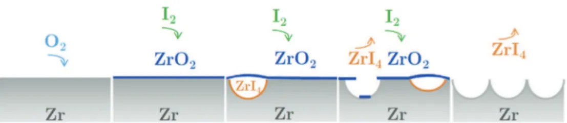
and numerous SEM observations, the following pitting mecha-nism is proposed.Fig. 21illustrates the proposed mechanism.
(1) Oxygen reacts with the substrate causing the oxide film to grow
(2) Iodine penetrates the growing oxide layer.
(3) The iodine reacts with the zirconium substrate below the oxide layer and forms gaseous zirconium tetraiodide (ZrI4). (4) The resulting gas pressure causes the oxide layer to crack,
and some pieces of broken oxide fall into the pits. Alterna-tively, once the pit has formed, the oxide layer crumbles and falls into the pits.
(5) Eventually the entire oxide layer flakes off, leaving the entire zirconium surface covered in pits, which corresponds to the generalized pitting phase previously mentioned.
Further investigations are being conducted to better understand the oxide-iodine interaction. Issues that are being studied include the mechanism by which iodine passes through the oxide layer, and the mechanism by which the oxide disappears. It should be noted that in the current study, pitting began during the heating phase before the samples reached the final test temperature and did not appear to depend on stress, strain or temperature. Consequently, contrary to Fandeur's approach[7], oxide layer cracking was not
Fig. 20. SEM micrographs of a zirconia layer above pits (arrows indicate shards of oxide). Fig. 19. Comparison between this work and previous studies on unirradiated CWSR
Zircaloy-4 cladding tubes for creep tests at 350"C in an iodine vapor environment and
considered as a limiting step for iodine induced stress corrosion crack initiation.
6. Conclusions
The objective of this research was to study the stress corrosion cracking of CWSR Zircaloy-4 fuel cladding in an iodine vapor environment with different loading modes, including constant in-ternal pressure tests (creep tests), constant strain rate tests (strain rate tests), and constant strain tests (relaxation tests). After the tests, specimens were examined by SEM to study the attack of the inner surface of the tube by iodine, and to characterize the fracture mode on the crack faces. The tests revealed an apparent I-SCC threshold stress around 240 MPa, below which sample failure by SCC does not occur before 72 h. This threshold stress value appeared to be independent of temperature in the range 320"Ce380"C and independent of the loading mode. A model for cladding failure via I-SCC was created based on the results of the creep tests using a progressive Kachanov's damage law and a vis-coplastic material behavior law coupled with finite element simu-lations. The model, which gives priority to stress and time, is able to reproduce the experimental data from both creep tests and relax-ation tests, and can predict the time-to-failure and the strain-at-failure of the samples reasonably well.
Acknowledgement
Financial support was provided by CEA/SEMI, EDF and AREVA NP. The authors are grateful to AREVA NP for providing the material. Technical support by J-F. L!ecot and J-L. Lacour is also gratefully acknowledged.
References
[1] B. Cox, Pellet-clad interaction (PCI) failures of zirconium alloy fuel cladding d a review, J. Nucl. Mater 172 (1990) 249e292.
[2] J.H. Davies, H.S. Rosenbaum, J.S. Armijo, R.A. Proebstle, T.C. Rowland, J.R. Thompson, E.L. Esch, G. Romeo, D.R. Rutkin, Irradiation tests to charac-terize the PCI failure mechanism, in: Proceeding Water React. Fuel Perform. Am. Nucl. Soc. Top. Meet, 1977, pp. 230e242.
[3] J.C. Wood, Factors affecting stress corrosion cracking of zircaloy in iodine vapour, J. Nucl. Mater 45 (1972) 105e122.
[4] K. Une, Threshold values characterizing iodine-induced SCC of Zircaloys, Res. Mech. 12 (1984) 161e188.
[5] P.S. Sidky, Iodine stress corrosion cracking of Zircaloy reactor cladding: iodine chemistry (a review), J. Nucl. Mater 256 (1998) 1e17.
[6] K. Une, Influences of cesium and cesium oxide on iodine stress corrosion cracking of Zircaloy-2 in out-of-pile and in-pile conditions, J. Nucl. Mater 87 (1979) 207e210.
[7] O. Fandeur, Etude exp!erimentale et mod!elisation m!ecanique de la corrosion sous contrainte des gaines en Zircaloy-4, Ecole Centrale Paris, 2001. PhD report.
[8] P. Hofmann, J. Spino, Determination of the critical iodine concentration for stress corrosion cracking failure of Zircaloy-4 tubing between 500 and 900"C,
J. Nucl. Mater 107 (1982) 297e310.
[9] R.L. Jones, F.L. Yaggee, R.A. Stoehr, D. Cubicciotti, Threshold conditions for
iodine-induced stress corrosion cracking of unirradiated zircaloy-4 tubing under internal pressurization, J. Nucl. Mater 82 (1979) 26e38.
[10] A.K. Miller, H. Ocken, A. Tasooji, Iodine stress corrosion cracking of zircaloy: laboratory data, a phenomenological model, and predictions of in-reactor behavior, J. Nucl. Mater 99 (1981) 254e268.
[11] A. Atrens, G. Dannh€auser, G. B€aro, Stress-corrosion-cracking of Zircaloy-4 cladding tubes: Part 1. Threshold in the presence of iodine, J. Nucl. Mater 126 (1984) 91e102.
[12] I. Schuster, C. Lemaignan, Influence of texture on iodine-induced stress corrosion cracking of Zircaloy-4 cladding tubes, J. Nucl. Mater 189 (1992) 157e166.
[13] S.Y. Park, J.H. Kim, M.H. Lee, Y.H. Jeong, Stress-corrosion crack initiation and propagation behavior of Zircaloy-4 cladding under an iodine environment, J. Nucl. Mater 372 (2008) 293e303.
[14] L. Brunisholz, C. Lemaignan, Iodine-induced stress corrosion of Zircaloy fuel cladding: initiation and growth, in: Zircon. Nucl. Ind., ASTM International, West Conshohocken, 1987, pp. 700e717.
[15] K. Videm, L. Lunde, T. Hollowell, K. Vilpponen, C. Vitanza, Cracking of cladding tubes caused by power ramping and by laboratory stress corrosion experi-ments, J. Nucl. Mater 87 (1979) 259e267.
[16] B. Baurens, J. Sercombe, C. Riglet-Martial, L. Desgranges, L. Trotignon, P. Maugis, 3D thermo-chemicalemechanical simulation of power ramps with ALCYONE fuel code, J. Nucl. Mater 452 (2014) 578e594.
[17] R. Limon, S. Lehmann, A creep rupture criterion for Zircaloy-4 fuel cladding under internal pressure, J. Nucl. Mater 335 (2004) 322e334.
[18] W.S. Ryu, Y.H. Kang, L. Jai-Young, Effects of iodine concentration on iodine-induced stress corrosion cracking of zircaloy-4 tube, J. Nucl. Mater 152 (1988) 194e203.
[19] J.C. Wood, B.A. Surette, I.M. London, J. Baird, Environmentally induced fracture of zircaloy by iodine and cesium: the effects of strain rate, localized stresses and temperature, J. Nucl. Mater 57 (1975) 155e179.
[20] S. Shimada, M. Nagai, A fractographic study of iodine-induced stress corrosion cracking in irradiated Zircaloy-2 cladding, J. Nucl. Mater 114 (1983) 222e230.
[21] CEA, Cast3M.http://www-cast3m.cea.fr.
[22] A. Soniak, N. L'Hullier, J.-P. Mardon, V. Rebeyrolle, P. Bouffioux, C. Bernaudat, Irradiation creep behavior of Zr-Base alloys, in: Zircon. Nucl. Ind. Thirteen. Int. Symp, 2002, pp. 837e862.
[23] D. Le Boulch, L. Fournier, C. Sainte Catherine, Testing and modelling iodine-induced stress corrosion cracking in stress relieved Zircaloy-4, in: Int. Semin. Pellet-Cladding Interact. Water React. Fuels, Aix-en-Provence, 2004. [24] I. Schuster, C. Lemaignan, Characterisation of Zircaloy corrosion fatigue
phe-nomena in an iodine environment: Part 1: crack growth, J. Nucl. Mater 166 (1989) 348e356.
[25] L.M. Kachanov, Rupture time under creep conditions, Int. J. Fract. 97 (1999) 11e18.
[26] L. Rouillon, F. Lefebvre, Influence de la temp!erature d’essai sur le d!eveloppement des fissures de CSC dans le Zircaloy-4 test!e en pressurisation interne, internal report, CEA Saclay, 1997.
[27] P. Magnusson, D. Le Boulch, A. Puranen, D. J€adern€as, G. Lysell, An experimental and Finite Element modeling study of cladding strain and localized stresses under simulated iodine-induced stress corrosion cracking, in: Proc. WRFPM 2014, Sendai, Japan, 2014.
[28] C. Anghel, A.-M. Alvarez Holston, G. Lysell, S. Karlsson, R. Jakobsson, J. Flygare, S.-T. Mahmood, D. Le Boulch, I. Arimescu, Experimental and finite element modeling parametric study for iodine-induced stress corrosion cracking of irradiated cladding, in: Proceedings of Top Fuel 2010, Orlando, Florida, USA, September 26-29, 2010 paper 111.
[29] C. Lemaignan, Controlled cracking of tubes, Int. J. Press. Vessel Pip. 15 (1984) 241e249.
[30] J. Lemaitre, J.-L. Chaboche, M!ecanique des mat!eriaux solides, 1996. [31] M. Peehs, F. Garzarolli, R. Hahn, E. Steinberg, Diskussion m€oglicher
mecha-nismen von PCI-Defekten, J. Nucl. Mater 87 (1979) 274e282.
[32] B. Gwinner, H. Badji, M. Benoit, N. Brijou-Mokrani, P. Fauvet, N. Gruet, P. Laghoutaris, F. Miserque, R. Robin, M. Tabarant, Corrosion of zirconium in the context of the spent nuclear fuel reprocessing plant, in: Proceeding Glob, 2015. Paris, 2015.