HAL Id: tel-03158868
https://tel.archives-ouvertes.fr/tel-03158868
Submitted on 4 Mar 2021HAL is a multi-disciplinary open access archive for the deposit and dissemination of sci-entific research documents, whether they are pub-lished or not. The documents may come from teaching and research institutions in France or abroad, or from public or private research centers.
L’archive ouverte pluridisciplinaire HAL, est destinée au dépôt et à la diffusion de documents scientifiques de niveau recherche, publiés ou non, émanant des établissements d’enseignement et de recherche français ou étrangers, des laboratoires publics ou privés.
Application to the Propulsion of Hybrid Aircraft
Amal Zeaiter
To cite this version:
Amal Zeaiter. Thermal Modeling and Cooling of Electric Motors : Application to the Propulsion of Hybrid Aircraft. Other. ISAEENSMA Ecole Nationale Supérieure de Mécanique et d’Aérotechique -Poitiers, 2020. English. �NNT : 2020ESMA0015�. �tel-03158868�
Pour l’obtention du Grade de
DOCTEUR DE L’ECOLE NATIONALE SUPERIEURE DE
MECANIQUE ET D’AEROTECHNIQUE
(Diplôme National – Arrêté du 25 mai 2016)
Ecole Doctorale :
Sciences et Ingénierie en Matériaux, Mécanique, Energétique
Secteur de Recherche : Energétique, Thermique et Combustion
Présentée par :
Amal ZEAITER
THERMAL MODELING AND COOLING OF ELECTRIC MOTORS.
APPLICATION TO THE PROPULSION OF HYBRID AIRCRAFT
Directeurs de thèse :
Matthieu FÉNOT Etienne VIDECOQ
Soutenue le 13 octobre 2020 devant la Commission d’Examen :
JURY
Présidente :
Eva DORIGNAC, Professeure des Universités, Université de Poitiers Rapporteurs :
Julien PELLÉ, Professeur des Universités, ENSIAME, Valenciennes Charbel HABCHI, Assistant Professor, Notre Dame University, Louaizé Membres :
Xavier ROBOAM, Directeur de Recherche CNRS, ENSEEIHT, Toulouse Matthieu FÉNOT, Maître de Conférences, ISAE-ENSMA de Poitiers Etienne VIDECOQ, Maître de Conférences, ISAE-ENSMA de Poitiers
Time is way too long for us now… but it was too short with you. You have given me the support, the encouragement, and everything I needed to begin the journey of my doctoral thesis, but you were not here when I’ve finished. Yet, your virtual presence is still inspiring me! You deserve a lot more than the dedication of the present work to acknowledge your past existence in this life for all your sacrifices.
This one is for you… I love you DAD <3
ACKNOWLEDGMENTS
En commençant la thèse, à part ce sentiment de fierté de pouvoir contribuer à l’avancement de la science ou du monde, on passe par une phase où l'on se projette dans le futur, au moment de la fin, mais on n'imagine pas le lot d'événements et de circonstances que l'on va traverser pendant ces quelques années. Je voudrais bien remercier de tout mon cœur toutes les personnes qui m'ont accompagnée, celles qui m'ont soutenue, et celles qui ont participé à la réalisation de la thèse jusqu'à la soutenance, voire au-delà.
Je tiens tout d'abord à présenter mes plus amples remerciements à M. Matthieu FÉNOT, qui a encadré ce travail de thèse, et à qui je suis profondément reconnaissante. Merci Matthieu pour tes conseils, ta confiance, tes recommandations judicieuses, mais surtout pour ta façon d'échanger sur les problématiques scientifiques. C'est avec beaucoup d'émotions que j'écris ces quelques lignes qui ne représentent que très peu de ce que j'ai à te dire pour te remercier encore, autant sur le niveau académique de la recherche que sur le niveau humain. J'ai eu la chance de te connaître et d'avoir effectué la thèse sous ta direction.
Je remercie profondément M. Etienne VIDECOQ tout d’abord pour son co-encadrement de thèse. Je suis consciente que tout le travail que nous avons effectué et les échanges scientifiques fructueux que nous avons eus m'ont permis d'avancer efficacement dans mon travail. Pourtant, si je tiens à te remercier, Etienne, c'est aussi pour avoir été présent durant la thèse surtout aux moments les plus délicats, pour avoir été patient mais toujours critique pour perfectionner le travail, et pour avoir donné les remarques pertinentes et suggestions scientifiques sincères et adaptées. Je te remercie également pour tout ce que j'ai appris de toi.
Merci Matthieu et Etienne d’être vous, parce que vous êtes des vrais encadrants, et je n’ai jamais arrêté d’apprendre de vous, de votre pédagogie, et surtout de l’intégrité scientifique et de l’esprit de progression pour le développement que vous portez en vous.
J’adresse mes remerciements aux rapporteurs de la thèse M. Julien PELLÉ et M. Charbel HABCHI. Je vous remercie d'avoir pris le temps d'évaluer le travail, de votre lecture très attentive du mémoire ainsi que de vos remarques précieuses. Je vous remercie également d'avoir participé au jury de soutenance. Grâce à cette participation, j’ai reçu des avis d’experts que j’apprécie infiniment et que je garderai dans mon esprit scientifique pour le futur. Ce n'est pas toujours le cas dans un jury de soutenance d'avoir des chercheurs qui travaillent dans des domaines assez variés. Je remercie Mme Eva DORIGNAC et M. Xavier ROBOAM d'avoir participé à ce jury et d'être venus partager leurs avis, leurs connaissances et leurs
expertises sur différents points de vue : thermique, énergétique, électrotechnique et intégration de systèmes. Je remercie également M. Yvan LEFEVRE et M. Jean-François ALLIAS pour leur participation au jury en tant qu'invités.
Pour nos échanges collaboratifs, un grand merci à la famille du projet HASTECS, de l’institut Pprime, M. Yves BERTIN, M. Vincent AYEL et M. Flavio ACCORINTI, ainsi que du Laboratoire Laplace et d’Airbus. Particulièrement, à toi Sarah, je voudrais te dire plus qu'un merci… J'ai gagné une vraie amie et j'apprécie énormément cette amitié et tous les échanges que nous avons eus durant ces années de thèse.
Merci également à l'Union Européenne pour le financement de la thèse, à l'ISAE-ENSMA de m'avoir accueillie en tant que doctorante, ainsi que l'Institut Pprime et l'École Doctorale SIMME, membres, directions et personnel administratif. Merci aux membres de l'équipe de thermique de Pprime, ceux avec qui j'ai eu des discussions et j'ai partagé des moments conviviaux qui resteront gravés dans mon cœur.
Mes remerciements vont aux personnes charmantes que j'ai côtoyées et connues à Poitiers et qui m'ont accueillie à différents endroits dans cette ville assez originale et élégante : A l'ENSMA, Mme Jocelyne BARDEAU, cette dame attachante et aimable, et dans ma grande famille à l'ASPTT, Mme Geneviève DELACHAUME et M. Gilles CATALOT, ainsi que tous les membres et instructeurs de l’aéroclub. Merci à la Team Pilates pour votre accueil chaleureux et convivial, et pour les moments sportifs, spirituels et humains que nous avons partagés. Je remercie les amis que j'ai connus ici, pour tous les beaux souvenirs que nous avons créés. Merci surtout à celles et ceux qui réussissent toujours à avoir un esprit positif et à rehausser le moral, merci pour leur compréhension lorsque la situation était compliquée.
Un merci du fond du cœur va à ma petite famille, mes frères et ma sœur, et à mes amis, sans votre support je ne serais pas arrivée à tenir le coup, j'espère que vous êtes fiers aujourd'hui de cet aboutissement.
A ma maman que j'aime infiniment, je ne pourrai jamais te dire autant de 'merci' que tu le mérites. Merci pour m’avoir supportée et soutenue toujours dans les hauts et les bas, surtout ces deux dernières années.
Si je veux remercier la personne qui a eu le plus grand impact sur mon arrivée à ce stade de mon parcours académique, c'est sans doute toi papa. Ton absence me laisse sans mots, mais pour tous tes sacrifices et pour ton encouragement infini, je vais garder la force et la motivation que tu m'avais léguées pour avancer toujours.
CONTENTS
ACKNOWLEDGMENTS ... iii
CONTENTS ... v
NOMENCLATURE ... ix
CHAPTER 1 ELECTRIC MOTORS FOR AIRCRAFT PROPULSION ... 1
1.1 Introduction ... 2
1.2 HASTECS: The Project under CleanSky II ... 2
1.3 Why Hybrid Aircraft? ... 5
1.3.1 Environmental Issues, Reality or Myth? ... 5
1.3.2 Towards Transportation Electrification and Hybridization ... 8
1.4 Electric Motors for Vehicle Propulsion ... 10
1.4.1 Overview of Electric Motors Types ... 12
1.4.2 From Ground to Air Vehicles Examples ... 19
1.4.3 Electric Motors, Suitable but? ... 24
1.5 Thermal Issues in Electric Motors ... 25
1.6 Purpose and Thesis Contents ... 25
CHAPTER 2 E-MOTOR THERMAL MANAGEMENT STATE OF THE ART ... 27
2.1 Introduction ... 28
2.2 Heat Transfer in Electric Machinery ... 28
2.2.1 Conduction Mode ... 29
2.2.2 Convection Mode ... 33
2.3 Electric Motor Cooling Methods ... 48
2.3.1 External Cooling Methods ... 49
2.3.2 Internal Cooling Methods ... 59
CHAPTER 3 LUMPED PARAMETER THERMAL MODELING ... 75
3.1 Introduction ... 76
3.2 LPTM Approach ... 76
3.3 Electric Motor System Definition ... 80
3.3.1 E-Motor Geometry and Materials Properties ... 81
3.3.2 Boundary conditions ... 82
3.3.3 Electric Motor Losses (Heat Sources) ... 82
3.3.4 Initial Conditions ... 87
3.4 Modeling Assumptions ... 87
3.4.1 Geometry ... 87
3.4.2 Symmetry and Periodicity for Model Reduction ... 88
3.4.3 Temperature-Independent Media Physical Properties ... 89
3.5 LPTM Construction ... 89
3.5.1 Thermal Conductance Matrix G ... 89
3.5.2 Thermal Capacity Matrix C ... 91
3.5.3 Heat Sources and Heat Sinks Vector Ψ ... 91
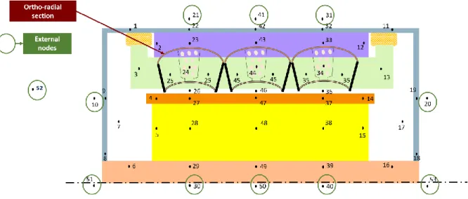
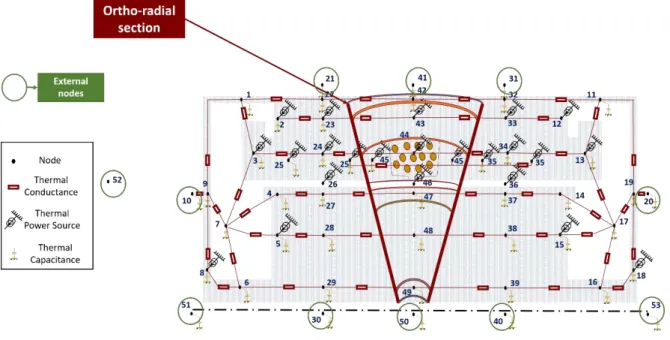
3.5.4 Space Discretization and Nodal Network ... 91
3.6 Thermal Properties of Components ... 95
3.6.1 Equivalent Properties of Heterogeneous Components ... 96
3.6.2 Contact Thermal Resistance ... 101
3.7 Validation with Experimental Results ... 103
3.8 Conclusion ... 106
CHAPTER 4 THERMAL MANAGEMENT OF DESIGNED E-MOTORS ... 107
4.1 Introduction ... 108
4.2 Electric Motor Design for 2025 (EM2025) ... 108
4.2.1 Thermal Constraint Evaluation ... 109
4.2.3 Thermal and Physical Properties ... 115
4.2.4 Dynamical Profile of Power ... 116
4.3 Cooling System ... 118
4.3.1 Thermal Resistance Analysis ... 119
4.3.2 Nodal Network ... 124
4.3.3 Cooling technology ... 126
4.3.4 Heat Exchanger of Cooling System ... 128
4.4 Thermal Behavior of the System ... 135
4.4.1 Thermohydraulic Parameters and Characteristics ... 136
4.4.2 Results and Analysis ... 138
4.4.3 Influence of Thermophysical Parameters Variation ... 147
4.4.4 Fluid Choice ... 150
4.4.5 Exchanger Surface and Coolant Flows ... 154
4.5 Case-studies ... 157
4.5.1 Influence of Flight Mission Scenarios ... 157
4.6 Electric Motor for 2035 ... 158
4.6.1 Motor Cooling System Choice ... 159
4.6.2 First Motor Design and Results ... 161
4.6.3 Second Design for EM2035 ... 165
4.7 Conclusion ... 171
CHAPTER 5 MODEL INVESTIGATION AND INVERSE METHOD ... 173
5.1 Introduction ... 174
5.2 Sensitivity of Motor Temperature to Losses ... 174
5.3 Losses Identification using an Inverse Method ... 178
5.3.1 Interest and Background ... 178
5.3.2 Heat Transfer Equation ... 179
5.3.4 Inverse Problem Solution ... 181
5.3.5 Results and Analysis ... 185
5.4 Conclusion ... 195
CHAPTER 6 CONCLUSIONS AND PERSPECTIVES ... 197
6.1 Conclusions ... 198
6.2 Perspectives ... 200
FUNDING ACKNOWLEDGMENT ... 203
CHAPTERS’ SUMMARIES IN FRENCH ... 205
NOMENCLATURE
Variables and Parameters
𝑇 temperature °C
ℎ convection heat transfer coefficient W·m2·K1
𝐷 diameter m or mm 𝑐, 𝑐𝑝 specific heat J·K1·kg1 𝑔 gravitational acceleration m·s2 𝐿 or 𝑙 length m 𝑢 velocity m·s1 𝑟 radius m or mm
𝑄̇𝑖 heat generation in motor system W
V volume m3 P electric losses W H hydraulic losses m S surface m2 𝑠 section m2 t time s t time step s 𝑞 flow rate m3·s1
𝑚̇ mass flow rate kg·s1
A linear surface current density kA·m1
J current density A·mm2
R thermal resistance K1·W
ℛ electrical resistance Ω
N number of nodes
₵ moment coefficient (for friction)
nf number of future times for specification function
np number of heat sources
nq number of outputs
nt number of time steps
Greek symbols
𝜑 heat flux density W·m2
𝜆 thermal conductivity W·m1·K1 𝜔 rotational velocity RPM 𝛷 heat flux W 𝜇 dynamic viscosity kg·m1·s1 𝜌 density kg·m3 ϼ electrical resistivity Ω·m 𝜈 kinematic viscosity m2·s1
𝛽 coefficient of thermal expansion K1
U mean quadratic error for U W
Y main quadratic error for Y, °C
χ characteristic space function
system domain
Matrices and vectors
𝐺 conductance matrix W·K1
𝜓 heat sink vector W
𝐶 thermal capacity matrix J·K1
𝛹 vector representing heat generation term in the matrix form W
𝐴 (N,N) state matrix
𝐵𝑐 (N) command vector relative to environment
𝐵𝑝 (N,np) command matrix relative to heat sources
𝐶𝑜 (nq,N) output matrix
𝐼 identity matrix
P heat source vector W
U vector of unknown heat sources W
K vector of known heat sources W
V vector of known inputs
vol volume m3 Y (nq) output vector Dimensionless numbers 𝑁𝑢 Nusselt number 𝑃𝑟 Prandtl number 𝑅𝑒 Reynolds number 𝐺𝑟 Grashof number 𝑅𝑎 Rayleigh number 𝑇𝑎 Taylor number Abbreviations WP Work-Package EV Electric Vehicle
HEV Hybrid-Electric Vehicle
HASTECS Hybrid Aircraft Academic reSearch on Thermal and Electrical Components Systems
MTOW Maximum Take-Off Weight
MEW Maximum Empty Weight
DC Direct Current
AC Alternating Current
NdFeB Neodymium Iron Boron
Sm2Co17 Samarium Cobalt
LPTM Lumped Parameter Thermal Model
PMSM Permanent Magnet Synchronous Machine
SM Surface Mounted
PCM Phase Changing Material
EM2025 Electric Motor for year 2025 EM2035 Electric Motor for year 2035
FTS Future Time Steps
Subscripts 𝑐𝑣 convective 𝑤 wall ref reference ℎ hydraulic 𝑝 at constant pressure 𝑐𝑟 critical ext exterior k time index
f for fluid at a surface
𝑟𝑠 rotor-stator
𝑟 with respect to radius
𝑒𝑙 for electrical
𝑎𝑔 or 𝑔 for airgap
𝑎𝑥 for axial
𝑟𝑎𝑑 for radial direction
𝑎𝑛𝑔 for angular direction
𝑙𝑎𝑚 for laminations
𝑖𝑛𝑠 for insulation material
cu for copper ch for channel Superscripts * noisy temperature ^ estimated value T transposition sign -1 inverse of a matrix 𝑐𝑜𝑛𝑑 for conduction 𝑐𝑜𝑛𝑣 for convection 𝑓 for fluid
radial for radial direction 𝑎𝑥𝑖𝑎𝑙 for axial direction
CHAPTER 1
ELECTRIC MOTORS FOR AIRCRAFT
PROPULSION
Synopsis:
A presentation of the subject area of the thesis and its problematics is developed in this chapter. Moreover, electric motors main characteristics and issues are summarized to
1.1
Introduction
Electric propulsion of vehicles is being increasingly investigated recently for a possible reduction in gas emissions and particulates. Besides the challenge of switching to a new architecture that goes with this goal, constraints relative to electric motors are defying the design of electric propulsion systems. Indeed, due to limited space and weight in vehicles, high-performance compact motors are strongly required. Fortunately, the technological advancements in materials and technologies have enabled the development of a new generation of high specific power motors (up to a few kW/kg). Generally in the transportation sector (ground, marine, and aeronautical applications) and specifically for cars, a turning point in the electric machinery domain has been registered during the last decade, highlighted by the rising interest in developing Electric Vehicles (EV) and Hybrid-Electric Vehicles (HEV). While propulsion electrification and hybridization are considered a promising solution for environmental pollution, electric motors in the aeronautical domain are constrained by several issues such as performance, weight, altitude, external conditions, safety, etc.
The objective of this chapter is to approach the thesis topic, by defining some important concepts and clarifying the basics in this subject area.
1.2
HASTECS: The Project under CleanSky II
This work is carried out within the framework of a project called HASTECS (Figure 1.1), standing for Hybrid Aircraft Academic reSearch on Thermal and Electrical Components Systems). This project kick-started in September 2016 and is currently running until 2021.
The hybrid-electric propulsion model consists of several inputs for electrical and thermal engines’ systems (i.e. Mach number and altitude as a function of time) that contribute to determining the Maximum Take-Off Weight (MTOW) of the plane at each iteration in a global optimization process as depicted in Figure 1.2. The Maximum Empty Weight (MEW) is given by Airbus, and the loopback on this weight is performed using a simplified function, subject to specific constraints (for instance, the drag effect not taken into account). HASTECS project is located at the electric propulsion units’ design and studies, aiming to reach the propulsion target in terms of weight.
Figure 1.2 : Hybrid Aircraft power chain with HASTECS project-area [HASTECS Workshop October 2018].
The general objective of HASTECS project, indicated in the project proposal, is to support Hybrid Electric Aircraft propulsion demonstration by developing electro-thermal models and tools to assess the main benefits of different hybrid propulsion architectures and power management for short/medium-range aircraft.
These means will help to design propulsive electrical architectures for radical aircraft, by setting specific objectives for different Work-Packages (WPs). System-level integration of the assessments is the task assigned to the Work-Package 6 of the project (WP6) from main components design and analysis of the hybrid power chain (see Figure 1.3). This chain consists
of electric machine designs (WP1), associated cooling systems (WP3), power electronics and cables (WP2, 5), and associated thermal management (WP4). It considers the main environmental constraints, especially the partial discharges (WP5) due to high-power-ultra-high voltage new standards.
The project is funded by the CleanSky2 Joint Undertaking under the European Union’s Horizon 2020 research and innovation program. For short and long-term targets, objectives have been fixed in terms of specific powers considering reasonable possible development in materials choices, and technologies. The specific power of electric machines is doubled from 5 kW/kg for 2025 to 10 kW/kg for 2035, while specific powers of converters must be increased from
15 kW/kg for 2025 to 25 kW/kg for 2035. For instance in electric machinery, the properties of
new insulators, impregnation materials, and magnets, are currently being investigated in industries and research institutes to be applied in the long-term future, while it is confirmed for other promising materials that they will be available to use in electric machinery in the short-term future.
The current thesis is registered to work on WP3. The electric machines specialists of WP1 provide multiple designs of motors to match the short-term and long-term targets (2025 e-motor and 2035 e-motor). A strong interaction between our Work-Package (WP3) and WP1 has been developed during the project running time. Both workgroups have been collaborating to harmonize tools and models to meet the specific power density targets considering the electrical and thermal constraints and motor efficiencies.
To exceed the existing limits of motor specific power density, HASTECS electric machine and heat transfer specialists mutualized their electromagnetic and thermal investigations to find genuine technological solutions. From a thermal point of view, the interaction requires first a definition of some basic points: electric motor types, the specificity of electric motor for propulsion, the limiting constraints in terms of temperature and weight, origins of thermal problems in these motors, and possible configurations that could be suitable in this groundbreaking application.
Figure 1.3 : HASTECS Project Work-Packages scheme for interactions.
In this framework, the objective of this thesis, concisely termed ‘Electric Motor Cooling’ or WP3, is to elaborate thermal models for super-high specific power electric motors, conceived in the project, and to configure suitable cooling systems. It aims to design and assess adequate techniques for the thermal management of such motors. With the existing technologies, the electric motors compactness and power are toughly limited by thermal constraints that should be respected. Also, with the high targets of global performance and specific power, motors for aeronautical propulsion should be investigated acutely from electro-technical as well as thermal points of view.
These points are the topic lead-ins of our study and will be developed successively in the thesis.
1.3
Why Hybrid Aircraft?
1.3.1 Environmental Issues, Reality or Myth?
The increased carbon footprint is challenging scientists, researchers, and environment specialists to raise interest and investigate other sustainable energy supply sources. The resulting anomaly is alarming with an increasing average land-sea temperature. This will change the global vital conditions on earth, together with higher frequency and intensity of heatwaves, hazardous fire weather, and drought conditions in multiple zones of the earth [1].
Many are the indicators of climate change and global warming, could it be the air temperature, ocean warming and sea-level rise, extreme weather events, or the changing rainfall patterns resulting from the changing global water cycle and intensifying with a warming climate. NASA [2] provided data on global temperature variations, as depicted in Figure 1.4. The rising temperature curves in the past decades prove that the warming effect on earth is rapidly growing. The climate models are developed, according to intermittent factors, to simulate and predict the responses of environment temperatures to all influencing factors [3]. Ignoring the alerting signs indicates that global surface warming will follow the trend line indicated in red in Figure 1.5.
Figure 1.5 : Global surface warming evolution in time with future projection scenarios [3].
It is thought that if no concrete actions are adopted to reduce greenhouse gas emissions considering plausible emission scenarios, by the end of the current century, the average temperature could increase between 2 °C and 6 °C.
The European Union is committed to meet technical environmental goals set in the European Commission’s Flightpath 2050 Vision for Aviation, which is to reduce by 75% CO2 and by 90% NOx emissions, and by 65% the noise. Data and statistics of the International Energy Agency ‘IEA’ [4] show that actually ‘transport’ sector accounts for around a quarter of global CO2 emissions in the world, as seen in the diagram of Figure 1.6.
With that being said, the transportation sector, implying broad private companies and industries, is now seeking sustainability for propulsion power systems mainly, and for other deployments as well. One can cite, for instance, the CO2 roadmap at Airbus. They, among other companies in this sector, are willing to achieve sustainable air travel soon, through greater decarbonization (a reduction of 50% of the net aviation carbon emissions by 2050 compared to what they were in 2005), by improving environmental performance and adopting sustainable supply chain, etc [5].
Figure 1.6 : Global CO2 emissions by sector in 2017 [4].
A key objective is to conceive and produce transportation means that consume less fuel or other « new » and cleaner energy sources and therefore reduce toxicity emission levels.
1.3.2 Towards Transportation Electrification and Hybridization
Vehicles have been powered, for a long time, predominantly by fuel of fossil - or biomass - origins that ignite in their heat engines emitting pollutant substances and gases. As for cars and ground vehicles, propulsion hybridization is thought to be an ecological solution for planes as well.
Aircraft hybridization (with solar power such as Sunseeker II [6] or electric power such as the Pipistrel Taurus Electro G2.5 [7]), and aircraft electrification (Siemens’ electric aircraft designs [8] as an example) was recently investigated as a solution to enable achieving the aforementioned environmental goals. To accelerate electrification, Rolls Royce Company - in partnership with YASA electric motor and controller manufacturer and Electroflight aviation start-up - has started an initiative called ACCEL[9], within which an all-electric powered aircraft with zero-emissions was unveiled in late December 2019 in an Iron Bird test airframe as shown in Figure 1.7. This plane, characterized by its high speed (over 480 km/h), is scheduled to take off in 2020. On the other hand, the first flight of the largest commercial all-electric aircraft (flying testbed) took place on May 28, 2020, with a Cessna 208B Grand
Caravan from AeroTEC company [10]. With a propelling electric motor from MagniX of
560 kW power, the zero-emissions flight lasted 30 minutes at a maximum of 2500 ft.
Figure 1.7 : ACCEL Iron Bird test airframe [9].
These light aircraft units and prototypes showed the extent and the limits of using less-pollutant energy types for propulsion. However, the tough environmental objectives suggest taking firmer actions and pushing the boundaries as far as enabling hybridization of regional aircraft in the same standard. The aerospace companies and industries are investigating the use of electric power for hybrid-electric propulsion of commercial aircraft. Electricity is retained as a potential candidate for hybridization in the aeronautical transportation sector, with the lack of other powerful energy sources.
Receiving funds from the Boeing Company and the state of Washington, Zunum Aero [11] is working on the development of a hybrid electric private jet. NASA STARC-ABL [12] is the established concept of Single-Aisle Turboelectric Aircraft with an Aft-Boundary-Layer propulsor, to be more fuel-efficient than existing aircraft designs. With a large turbofan engine on the rear of the aircraft and generators added to wing-mounted turbofans supplying the back engine with generated electricity, this plane is designed to use 10% less fuel, promoting longer ranges of aircrafts for a long-term goal of two decades. NASA researchers are still carrying out tests on future turboelectric (and besides hybrid-electric) concepts of electrical components and systems (PEGASUS [13]). Airbus, Rolls Royce, and Siemens engaged to switch to hybrid electric propulsion of commercial air vehicles. Airbus company is thought to be a major player and enabler to reduce considerably the emissions of CO2, NOx, and particulate [14]. Their
E-Fan project aims to develop an e-system architecture and other related electrical propulsion technologies. Spotted with the launching of the E-Fan X hybrid-electric aircraft demonstrator [15] (see design in Figure 1.8), the year 2019 has also witnessed many transportation electrification events sponsored by the primary actors in the aircraft design industry (chiefly, but not limited to, Airbus and Boeing companies). Recently, the E-Fan X project was canceled during the COVID-19 pandemic.
Figure 1.8 : E-Fan X demonstrator design [15].
Those major advancements in electrification and hybridization of commercial aviation are being led towards a less polluted environment and more sustainable actions in the air transportation sector.
Before getting through more details, let us comprehend the possibility of switching to electrical propulsion and its limitations, by getting through some general definitions and conventions.
1.4
Electric Motors for Vehicle Propulsion
In addition to their environmental benefits, electric motors have a proven advantage over gasoline engines, which is their higher specific torque. The curves from [16] in Figure 1.9a show the performance characteristics, in terms of torque and power, of two Internal Combustion Engine (ICE) that propel Renault Fluence 1.6 16V 110 and Renault Fluence dCi 105. The electric motor propelling the same vehicle model: Renault Fluence Z. E. battery electric vehicle,
is compared. Torque and power diagrams as function of speed are simultaneously depicted in
Figure 1.9b. At certain conditions of grades, the performance of the EV is higher. Furthermore, Figure 1.9a and Figure 1.9b prove that at low speed the electric motor supplies a satisfactory
torque for starting, which is not the case for thermal engines.
(a) (b)
Figure 1.9 : Comparison between performance characteristics of (a) petrol ICE, diesel ICE, and (b) electric motor. Motors are used to propel the variants of the same vehicle model: Renault Fluence 1.6
16V 110, Renault Fluence dCi 105, and Renault fluence Z. E. respectively.
With the arising tendency to switch to electrified propulsion, the electric drive systems are one of the major components in the chain, provided that the electricity powering these drives is safely and continuously supplied. The development of these drives and motors belongs to the electric machinery and power systems industry. As the thesis concerns only the electric motor area, it is important to understand the topology of these machines. Herein, the first subsection overviews the main electric motor types, and the second subsection focuses on propulsion application types. Since technical information has not been published for air vehicles application, only electric motors developed for ground vehicles are presented. Besides, information is given on how these motor types can be derived for aircraft propulsion application.
1.4.1 Overview of Electric Motors Types
Back to the basics, electric motors are by definition devices that convert electrical energy into mechanical energy. This conversion is based on an electromagnetic process similar to a rectangular loop conductor placed in a magnetic field and through which a current passes. It will rotate due to the generated force applied to it, whose direction is determined based on Fleming’s left-hand rule. Electric motors are classified as rotary electrical machines that require to be fed with electricity as input energy, and their application relies mainly on the resultant rotating motion as kinetic energy output. In their topology, a rotor and a stator are the main two parts of electric motors. Classically, the rotor is mounted on bearings so that the rotational motion is applied to a mechanical system (or load). The electrical energy supplying these motors can derive from Direct Current (DC) sources or Alternating Current (AC) sources.
From these statements, one can figure out that there are as many types of electric motors as there are operation principles and types of electrical energy sources. Two important categories depending on the electrical current type are presented hereafter which are the DC motors and AC motors. Other motor types are grouped in other electric motors’ category, which are motors with special characteristics that cannot be included in any of the former two categories. Motors types are presented briefly and characterized accordingly. The differences between the presented motor types are clarified. Besides, some examples of applications are given.
1.4.1.1 Direct Current Motors
DC motors are electric motors that are supplied with direct current electrical energy. The working mechanism is based on Faraday’s law of energy conservation from electrical to mechanical form. It is the first motor form working on the principle that when a voltage is applied to a conductor coil in a magnetic field, an electromagnetic force (Lorentz force) will be applied to the conductor driving it to rotate and producing a torque. There are different DC motors types: Shunt, separately excited, series, Permanent-Magnet DC, and compound.
The topology of these motors consists of the following parts: rotor, stator, airgap, winding, and brushed commutator. The airgap is the space that separates the rotor from the stator in which the magnetic field circulates. Winding is the coil made of wound conductors through which the current passes. The commutator in DC motors is the device that keeps switching the current direction in the rotor coil to ensure that the rotor will keep turning indefinitely in the static field,
i.e. the resulting force applied to the coil should change its direction every half rotation to lead to a rotating motion. Commutators consist of metallic segments and brushes mounted in a cylinder. Segments are connected by direct contact to rotor windings applying to them the electric current. Brushes are mounted on the commutator cylinder and are used to reverse the current direction.
The DC motors types are presented below:
Shunt Motor
A shunt motor has its rotor and stator windings, respectively named armature and field windings, electrically connected in parallel. A DC shunt motor is characterized by maintaining a constant speed regardless of the applied load.
Separately Excited Motor
The electrical energy supply is given from separate sources to field and armature windings. The DC voltage applied to the armature coil has a different source than the voltage source in the field winding. Coils are isolated from each other.
As for shunt motors, the electric current passing through the field coil in separately excited motors is constant and the field flux is also considered constant. However, with this latter type, it is possible to control the motor, compared to shunt motors where it is not possible.
Separately excited motors are used in industrial applications such as actuators.
Series Motor
In series wound DC motor, armature, and field windings are connected in series and the current flowing through both windings is the same. The main difference between these motors and shunt motors is that for series motors the speed varies with load. The torque is proportional to the squared current value. Thus, they are characterized by the highest obtained torque among all other motor types for the same current ratio. Series motors can be applied as starter motors in the automotive sector and as elevators’ motors.
Permanent-Magnet DC Motor
Permanent-Magnet DC motors (PMDC) have winding in the rotor (armature winding) but have magnetized permanent magnets mounted on the inner side of the stator to produce the field flux instead of windings (no field windings). The required flux density provided by magnets will be therefore constant, and permanent magnets are chosen in the construction phase accordingly. Their advantage is mainly their smaller size compared to other types of DC motors; their disadvantage is their low applied torque.
Compound Motor
In a compound wound DC motor, the connection between stator and rotor is a combination of connections of shunt and series excited DC motor windings. The field winding is connected both in parallel and in series to the armature winding. Two field coils are used for a compound working mechanism. These motors combine the efficient speed regulation property of shunt-wound motors and the high starting torque of series motors.
1.4.1.2 Alternating Current Motors
Alternating Current (AC) motors are electric motors supplied with AC voltage. There are two main types of AC motors: Induction (or asynchronous) motors and synchronous motors.
Induction Motors (IM)
Induction motors or asynchronous motors are AC electric motors operating based on the principle that an induced current is created in a conductor (of the rotor) when placed in a rotating magnetic flux from the stator. The rotor induced current and stator current interact to produce a torque on the rotor.
Rotor part: The conductor is part of the rotor structure that is typically in the form of a squirrel cage with multiple conductor bars of aluminum or copper, connected cylindrically at both ends by rings (see Figure 1.10a). The bars are short-circuited by the rings, which allows the creation of the induced current. Inside the cage, steel laminations are stacked around the shaft. The rotating magnetic field from the stator and the induced current in the rotor drives this latter into rotation due to the generated force.
(a) (b)
Figure 1.10 : Squirrel cage rotor (a) and stator (b) of an Induction Motor
Stator part: The construction of the induction motor stator, as depicted in Figure 1.10b verifies the role of this part in inducing the magnetic field that penetrates the rotor. Its main part is made up of a laminated core (stack of laminations sheets) and one or more windings depending on the number of phases. Windings are encapsulated in slots and they carry supply current.
When starting the motor, the rotor begins to rotate in the same direction and at the speed of the rotating magnetic field of the stator. To keep up its rotation, electrically wise, it is crucial to vary either the induced current in conductors or the magnetic flux. In AC induction motors, the latter one is changed. Since the rotation at synchronism speed will not produce torque at the rotor mechanical connection, there should be a ‘slip’ between rotor speed and synchronous speed i.e. the rotor operates at a slightly lower speed. When a load is applied, the motor will adapt its speed to the load torque. As a resulting drawback, slip losses are generated in the rotor and these losses reduce the efficiency and lifespan of motors [17].
This motor type is generally known to require low-maintenance, to be easily constructed, and to be robust. It can be coupled to variable frequency drive-in applications that require controlling a load velocity and displacement. The induction machine can be applied as both generator and motor.
Synchronous Motors
In synchronous motors (SM), the rotor speed is equal to the stator current rotation speed. From an electromagnetic point of view, the rotor will be continuously lining up with the rotating magnetic field in the stator i.e. there is no slip between motor and stator current rotations.
The major difference between synchronous and induction motors is that synchronous motors have their rotors magnetized by external excitation (Wound-Rotor Synchronous Motor WRSM) or self-magnetization (Permanent-Magnet Synchronous Motor PMSM).
The stator of synchronous motors is structured similarly to that of an induction motor. The difference is in the rotor structure. There are two main SM rotor configurations: either with a wound rotor made with laminations and winding (also called electro-magnet) excited from a DC source or with permanent magnets within or at the surface of a laminated core.
They are used for devices of high precision positioning such as robots, as well as in powering elevators when coupled to variators. Their key advantages are their very high power factor (real power/apparent power ~ 1) and the constant motor speed regardless of the applied load. Permanent-Magnet motors support high overload current for fast kick-starting phase, while wound rotor synchronous motors are reversible electrical machine: they can operate as motors and as generators.
One of the drawbacks of synchronous machines is their operation failure in the case of overload torque.
1.4.1.3 Other Electric Motors
Stepper MotorA stepper motor is a DC motor that discretizes one rotation or revolution into multiple steps. Its stator is formed with a number of coils. Each winding group forms a phase. The steps are controlled by a computer, which gives them high precision characteristics in operation. There is a variety of stepper motors depending on the application requirement. Among these motors, one can site Permanent-Magnet or hybrid stepper motors, 2-phase bipolar or 4-phase unipolar.
Brushless DC Motor
Brushless DC motors as their name suggests, are brush-free and their operation is owed to an integrated electronic controller. They achieve higher performance and efficiency levels. The electronic controller eliminates the friction losses of a brushed commutator. They can be better adapted to applications. Brushless DC motors have a smaller size than AC motors of similar performance. They have a higher torque-to-weight ratio than brushed motors.
Hysteresis Motor
The hysteresis motor is a special synchronous self-starting electric motor without DC excitation. The stator rotating-field acts on the rotor as in induction motors. The hysteresis and eddy current induced in the rotor produce the torque. The stator of hysteresis motors is wound with coils similar to that of an induction motor. The rotor is made up of hardened steel laminations mounted on a nonmagnetic shaft [18]. The motor starts as in induction motors and runs as in synchronous motors. The motor has a smooth rotor with no teeth and no windings and operates soundlessly. The main drawbacks of this type are low efficiency and low output torque. It is generally used in sound equipment.
Reluctance Motor
Reluctance Motors (RM) are electric motors that produce torque through magnetic reluctance. The magnetic reluctance quantifies the opposition or resistance of a magnetic circuit to magnetic field penetration. In this motor type, the rotor is made from soft magnetic material without windings. The stator has multiple projecting electromagnet poles (or salient poles). The rotor laminations have multiple projections that act as salient poles through reluctance. Their number is lower than the number of stator salient poles to allow the generation of torque. They can be either synchronous reluctance or variable (or switched) reluctance (which are a subtype of stepper motors). Reluctance motors can reach high power density; they have low cost and easy maintenance features and have various applications from computer hard disk drive to electric vehicle propulsion as in Tesla Model 3.
Universal Motor
A universal motor is an electric motor that runs either on AC or DC source. Its stator consists of an electromagnet. Field and armature coils are connected in series. It has a wound rotor and a commutator with brushes. The motor structure is similar to the DC motors, but their stator and rotor are laminated to minimize eddy current losses. Universal motors are characterized by high starting torque similar to series DC motors. They can be found integrated into home appliances.
1.4.1.4 Summary of E-Motors Characteristics
In this subsection, Table 1.1 sums up the main advantages and disadvantages of each electric motor type that is applied in electrified vehicle propulsion based on [19].
Motor type Advantage Disadvantage
Brushed DC
Motor Maximum torque at low speed
Bulky structure Low efficiency
Heat generation at brushes
Permanent Magnet Brushless DC Motor
No rotor copper loss
More efficiency than induction motors Lighter
Smaller
Better heat dissipation More reliability More torque density More specific power
Short constant power range
Decreased torque with increase in speed
High cost because of PM
Permanent Magnet Synchronous Motor
Operable in different speed ranges without using gear systems
Efficient Compact
Suitable for in-wheel application High torque even at very low speeds
Huge iron losses at high speeds during in-wheel operation
Induction Motor
The most mature commutatorless motor drive system
Can be operated like a separately excited DC motor by employing orientation control
Very noisy Low efficiency
Larger and heavier than PM machines Complex design and control
Problems in controllability and manufacturing
Low power factor
Reluctance Motor
Simple and robust construction Low cost
High speed
Less chance of hazard Long constant power range High power density Robust Fault-tolerant Efficient Small PM assisted Synchronous Reluctance Motor
Greater power factor than Synchronous Reluctance Motors Free from demagnetizing problems
observed in PM
1.4.2 From Ground to Air Vehicles Examples
The modern era has been marked by a substantially increased interest in Electric Vehicle (EV) and Hybrid-Electric Vehicle (HEV) concepts in the ground transportation sector. These concepts have been emerging for over a century now but have become recently a driving trend. Vehicles’ propulsion electrification is shaping the future of the automotive industry with exponential development. Reviews of technologies used, benchmarking and an exhaustive database of these concepts are found in [20]–[24].
Vehicles’ industries and manufacturers have been developing EV and HEV to reduce both, emissions and fuel consumption. Tesla Models (3, S and X), Jaguar I-Pace, General Motor EV1, BMW i3, Hyundai kona and ioniq, Audi e-tron, Nissan Leaf, Renault Zoe, Hybrid Toyota Camry and Prius, Hybrid Honda Accord are, among others, examples of EV and HEV. Actually, with this revolution over the combustion engines, and their replacement in part or total with batteries, the type of electric motor is one of the major choices to be made in this field of investigation. Indeed, with the wide variety of options, it has been proved – based on the diversity of the adopted types in existing electrified vehicles - that a suitable type depends on the technological targets aimed to be reached and some economic constraints (mainly motor construction cost).
Once an electric motor category and type seem to fit the specifications and requirements, researchers launch a process of design and optimization. This same procedure is conducted for air vehicles or planes as well. However, constraints and targets are quite different since external conditions and issues at altitudes are not similar, and objective loads are by far greater.
The typical types of electric machines used in traction applications are presented in Figure 1.11 in assembled and exploded views. One can find that mainly the three presented types (Permanent-Magnet, Induction, and Switched-Reluctance machines) are the most suitable types for electrified powertrains allowing the engine to operate closer to its peak efficiency areas, lowering fuel consumption in hybrid vehicles [25].
Figure 1.11 : Typical electric machines for traction applications, (a) PMSM (with interior magnets configuration), (b) IM, (c) SRM [25].
Statistics on electric motors technology for EV and HEV propulsion during the last twenty years are depicted in Figure 1.12.
Figure 1.12 : The percentage distribution of electric machine technology in EV and HEV during the last twenty years, ‘dc’ (for DC), ‘IM’, ‘PMSM’, ‘SRM’, and ‘WRSM’ (Wound-Rotor Synchronous
Data from [22] show that over the last twenty years, the PMSM type is widely used for electric propulsion vehicles (73% of vehicles with electrified propulsion). With the addition of 2% of wound-rotor SM type, Synchronous Machine type has globally 75% of the share. IM machines were selected for around 18% of EV and HEV. DC machines are less employed because of their maintenance requirements [21] (6%). SRM are used for 1% of the existing vehicles' electric propulsion. Their external control is more complex than equivalent induction and DC motors [26].
The e-motor types used commonly in electrified propulsion of ground vehicles existing in the automotive market so far are listed hereafter with examples of each:
IM (Induction Motor): Tesla Model S 2012, Ford Think City 2008, and Honda Fit EV 2011, General Motors EV1 1996.
PMSM (Permanent-Magnet Synchronous Motor): Lexus LS 600h 2008, Toyota Prius 2010, Toyota Camry Hybrid 2007, Hyundai Sonata 2011, Nissan Leaf 2012, Honda Jazz 2012.
WRSM (Wound-Rotor Synchronous Motor): Renault ZOE 2011.
PM assisted SynRM (Permanent-Magnet assisted Synchronous Reluctance Motor): BMW i3 2012 [19] (hybrid Synchronous Motor type).
DC Motor: Peugeot Partner 1999 (Separately excited DC), Nice Mega City 2006. RM (Reluctance Motor): Tesla Model 3 2017 (Interior Permanent-Magnet Synchronous
Reluctance), Holden ECOmmodore 2000 (Switched Reluctance).
PMSM type has been used increasingly for electric-propulsion vehicles in ongoing decades, because of the high machine performances in terms of torque-to-power ratio [28]. Common examples of EV and HEV with axial-field PMSM are Toyota Camry Hybrid 2007, Lexus LS 600h 2008, Toyota Prius 2010, Hyundai Sonata 2011, and Nissan Leaf 2012. Their stators’ laminations are depicted in Figure 1.13.
Figure 1.13 : Stator and stator laminations of (a) Camry and LS 600h, (b) Prius, (c) Sonata, (d) Leaf
[28].
Figure 1.14 : Rotor laminations of different PM Machines in EV and HEV [23].
Rotor laminations and details of PM machines and other types used in vehicles’ propulsion are found in the benchmarking of [23]. According to the authors, a trend is noticed in the use of electric motors with higher rotational speed. This is mainly due to the fact that with higher speeds, motors with less weight, and a lower volume of structure are needed, to achieve the same power targets.
Targets of powerful motors with less weight, existing in ground vehicles, are indicated by the specific power of the motor. For air vehicles, more attention is drawn to this indicator since higher values should be achieved. The existing motors in ground vehicles (mostly including the cooling system) have their specific power values grouped in Table 1.2.from [29]. Lexus LS 600h (2008) is equipped with one of the highest specific power motors of around 2.5 kW/kg [24]. Vehicle model 2012 Leaf 2012 Sonata HSG 23 2011 Sonata 2010 Prius 2008 Lexus LS600h 2007 Camry 2006 Honda Accord 2004 Prius Power (kW) 80 8.5 30 60 110 70 12 50 Specific power (kW/kg) 1.4 1.9 1.1 1.6 2.5 1.7 0.5 1.1
Table 1.2 : Comparison between specific density of electric motor in EV and HEV based on [29].
Based on their multiple advantages in hybrid propulsion of vehicles, Permanent-Magnet Synchronous Motor type is considered suitable for our project’s application and targets (as a reminder: 5 kW/kg for the year 2025 and 10 kW/kg for the year 2035).
The selected motor for our project is of SM-PMSM type that is enclosed in a case. Laminations are made from soft-magnetic Co-Fe alloy. Materials are investigated and chosen at WP1 and some characteristics are extracted from catalogs. The rotor consists of laminated core and surface mounted Samarium-Cobalt magnets. NdFeB magnets could be an option for the machine unless simulations show that the temperature field in the magnet could exceed the maximum allowed value. The stator is made up of a laminated core with teeth-and-slots configuration and distributed windings in slots. The shaft consists of a steel rod. The motor frame is made of aluminum. In a modeling approach, a simplified motor section is depicted in
Figure 1.15 : Section of a simplified electric motor geometry for modeling.
1.4.3 Electric Motors, Suitable but?
One of the challenges met in e-motors with high performance, for power traction applications, for instance, is the thermal concern. When high performance is targeted, loads should be increased and the heat produced due to losses increases correspondingly as well. Since the heat flux in a system influences its thermal behavior, the e-motor temperature evolution depends on these losses. To reach high specific power values, required to maximize motor power and minimize its weight for propulsion application, loads should be increased wisely such that acceptable motor operating conditions are respected. Vice versa, loads are limited by motor thermal conditions, specifically, the maximum allowed temperature in winding insulation and the maximum operating temperature of permanent magnets. The excessive temperature increase may irreversibly demagnetize magnets [30] or could lead to shortening motor lifetime due to overheated electric insulation material [31]. Consequently, electrical machine cooling is becoming recently one of the biggest issues in the electrical machinery industry. The thermal issue in such high specific power density machines is brought back to the huge heat fluxes
generated in confined zones. The solution resides in a configuration where the produced heat is extracted from the motor core and simultaneously evacuated to a secondary cooling circuit. Extraction and evacuation of the heat through a cooling medium should be adapted efficiently so that the aforementioned limits are not exceeded, and no hot spot points are induced in motor sensitive parts.
1.5
Thermal Issues in Electric Motors
Stating that the emerging technologies aiming to increase specific power of motors and their efficiency and performance while economizing in production cost, has issued a serious thermal problem, researchers in electric machinery sector are concerned in finding suitable cooling solutions. To overcome the resulting thermal problem in electric motors and maintain acceptable temperatures in their critical components, some cooling techniques have been developed. In classical electric machines, traditional cooling methods managed to give satisfactory results in terms of temperature being maintained far below the limits. The machine cooling was handled sometimes with the simple natural convection as in Totally Enclosed Non-Ventilated (TENV) machines or with forced air-cooling through a fan as in Totally Enclosed Fan-Cooled (TEFC) type. These techniques rely on the machine ‘global cooling’ concept, which is adopted regardless of the heat generation location.
The developed e-motors, or prototypes being investigated, for the electrified vehicles’ propulsion, should have more sophisticated cooling than a global cooling concept, such as forced air or liquid cooling on specific areas. These techniques fall under the ‘specific and efficient cooling’ approach. During the design stage, motor cooling techniques and circuits must be accurately considered and integrated into thermal models to get reliable temperature results. This procedure requires sophisticated and detailed analysis and integration of coolant circuits’ to genuinely assessing the motor thermal behavior.
1.6
Purpose and Thesis Contents
The purpose of the present study is to thermally model specific motors designed in HASTECS project (Work-Package 1) for the propulsion of a hybrid aircraft and to find cooling solutions that could be integrated into this specific environment and context. To do so, we will start with
a presentation of the thermal characteristics and phenomena encountered in an electric motor in the following Chapter 2. Then, existing and future cooling solutions in electric machinery are reviewed and analyzed, to qualify their adaptability to our case-study motors.
Chapter 3 introduces the method that we will use for our model, which is the nodal network
modeling method, also termed Lumped Parameter Thermal Modeling. Based on the general energy balance equation, the general matrix form of the numerical model is displayed, for application on electric motors. The bare model of the motor system is built and validated on an existing industrial motor, as close as possible to the studied motors.
In Chapter 4, the two target motors of the project are presented and investigated. Based on the provided electromagnetic design, the electric motor for 2025 is thermally assessed. A double liquid-cooling system in frame and shaft and an end-windings potting are adopted to maintain temperatures below the imposed limits. The resulting temperature evolutions in the motor are discussed. Besides, multiple studies are carried out on this motor to investigate the effect of some parameters and particular scenarios on the thermal behavior of the overall system. The weight of the motor with its cooling system is computed to ensure reaching the targeted value of specific power for this short-term. Whereas, for the long-term target (electric motor for 2035), several electric motor designs were assessed, and two of them are presented in this chapter for comparison purposes. The second design is adopted, and the cooling system is configured accordingly. It consists of the same cooling circuit as the electric motor for 2025, with an additional liquid cooling circuit in windings slots.
Finally, Chapter 5 presents a study with slightly different objectives. The main goal of this chapter is to test and develop an inverse method based on the thermal model developed in
Chapter 3 and Chapter 4 to predict motor losses using noisy temperatures. Indeed motor losses
are generally difficult or impossible to measure directly. A thermal method allowing their identification would be a significant gain in the design and fabrication processes. A sensitivity study of motor temperatures to losses is conducted. It allowed determining the suitable locations of output data for each type of losses. Then, the sequential inverse method is presented. A regularization using Beck’s function specification technique is applied to get losses dynamical profiles in real-time. Different cases of unknown losses are tested, and low-accessibility temperatures are predicted with high precision using the determined losses in the forward model. The method gives accurate results proving its reliability and efficiency in terms of computation time.
CHAPTER 2
E-MOTOR THERMAL MANAGEMENT
STATE OF THE ART
Synopsis:
In this chapter, a literature review on the thesis topic is developed and a detailed theoretical background of the thermal management of e-machines is given.
2.1
Introduction
Conceiving the conceptual electric motors for aircraft propulsion with some tough specifications presented in Chapter 1 comes out with multiple issues related to the thermal constraints and the cooling concepts. A detailed review of all existing techniques used for the thermal management of these motors is crucial to initiate the investigation of this topic. Great time investment was accorded to create a full state of the art on e-motor thermal management and apprehend the thermal phenomena inside the motor. In literature, suggestions can be found for global and specific cooling solutions to deal with the encountered problems. Classical approaches as well as recent advancements in thermal management are both reviewed to choose the most adapted technologies for the targeted motors. Since our motors to be conceived should have a super-high specific power, it is expected to have specific zones with hot spot temperatures. Therefore, particular attention to cooling methods of targeted parts of the machine should be drawn, particularly for zones where global cooling methods seem to be less effective, and where promising solutions are required.
The main physically dissociated parts of the electric motor are the rotor, the stator, and the frame. Hereby, a state of the art on heat transfer (conduction and convection modes) and heat extraction in electrical machines is detailed. The issue of radiation heat transfer will be discussed later in this thesis. This review consists of the following parts:
i. Conduction heat transfer in the motor components
ii. Convection phenomenon specifically in airgap and end windings
iii. Renowned and groundbreaking cooling methods existing so far or being investigated for future application in electric machinery.
For simplification purposes, the symbols and letters used for variables in this chapter are not included in the Nomenclature section but are defined when mentioned.
2.2
Heat Transfer in Electric Machinery
Conduction and convection modes of heat transfer occurring in electric motors and their related issues are developed in this section. A general description of these modes and the definition of some important dimensionless numbers are presented.
2.2.1 Conduction Mode
The conduction mode of heat transfer is based on diffusion phenomena in a physical medium. Further information on the theory of heat transfer is found in [32], [33]. Studying the thermal conduction issue in an electric motor is related to assessing mainly the solid components of the motor. This assessment requires first specifying the adequate material for each component. Each material is chosen based on many criteria to meet the overall intended performance. The motor material composition and related conduction heat transfer occurring in the electric machines are known to be a complex and challenging problem that was investigated for decades. It is specifically challenging at some specific zones where hot spot temperatures, due to the low efficiency of conduction heat transfer, are encountered. When such problems occur at these levels, there will be no significant impact of optimizing other heat transfer modes (such as convection) on the thermal behavior of electric machines. Changing the materials, their ratios in heterogeneous elements, or even their dimensions would make a difference. However, any change in these characteristics will influence the loads of the machine and can affect its electrical performance. A trade-off decision is required between thermal and electromagnetic constraints.
The structure of the electrical machine consists of different parts as presented in Figure 2.1. In this configuration, the main machine components are the following: windings (made of coils), stator laminations, rotor laminations, motor housing (or frame), and eventually the magnets (in electrical machines with permanent magnets)
Each component will be described and studied from a thermal point of view. It will help to understand the element composition and structure and will allow figuring out the modeling of the conduction heat transfer in the motor.
2.2.1.1 Windings
The windings are formed with metallic coils covered by electrical insulation material(s), which can be generally a coat of insulator around the coil, traditionally a varnish, and lately, other constituents are added such as epoxy resin for impregnation. At the end-motor sides, the windings are coiled around the teeth, which creates a shape of wreaths that cover the stator at the cavities’ sides. These wreaths are called end-windings.
According to [35], the impregnation material of the end windings and stator slots affects quite significantly the thermal behavior in electric machinery. Their experimental data show that around these two regions, the temperature reaches a serious peak value. In this same context, the authors explained that the hot spot temperature found in one of these two regions is essentially due to the low thermal conductivity of the impregnation material. The filling insulation material of the windings prohibits an efficient heat extraction from the conductors. What is practically occurring in these zones is that the heat produced due to Joule losses, hardly extracted from the metal, will result in temperature rise and will require more cooling effort. For this purpose, deep investigations of these two parts (the end winding and stator slots) are conducted. Materials are classified according to their characteristics and properties: electric properties (especially resistivity, which is directly related to electrical resistance), density, and thermal properties (mainly specific heat capacity and thermal conductivity).
Nategh et al. [36]used varnish and epoxy (named Epoxylite, which is a specific trademark of Elantas PDG, Inc., St. Louis, MO, USA) for winding impregnation in their studied motors. They presented a practical approach to model the thermal effects in directly-cooled electric machines. But later the authors in [35] studied the SbTCM, a silicone-based material, with higher thermal conductivity than epoxy and varnish (3.2 W·m1·K1 compared to
0.85 W·m1·K1 for epoxy and 0.25 W·m1·K1 for varnish). They concluded that there is no change in thermal, mechanical, and electrical properties for the SbTCM under medium-term
![Figure 1.14 : Rotor laminations of different PM Machines in EV and HEV [23].](https://thumb-eu.123doks.com/thumbv2/123doknet/14718864.750773/37.892.110.776.420.760/figure-rotor-laminations-different-pm-machines-ev-hev.webp)

![Figure 2.9 : Resulting heat transfer coefficient according to location, at the end-winding region [74]](https://thumb-eu.123doks.com/thumbv2/123doknet/14718864.750773/61.892.135.727.120.528/figure-resulting-transfer-coefficient-according-location-winding-region.webp)
![Figure 2.27 : Spray cooling over a square test surface in stagnation at 0° angle inclination and 8.66 mm standoff distance [154]](https://thumb-eu.123doks.com/thumbv2/123doknet/14718864.750773/85.892.265.628.273.533/figure-spray-cooling-surface-stagnation-inclination-standoff-distance.webp)

![Figure 3.7 : General Electric nomograph for the thermal equivalent conductivity in heterogeneous materials with different configurations [47]](https://thumb-eu.123doks.com/thumbv2/123doknet/14718864.750773/113.892.215.679.511.802/electric-nomograph-equivalent-conductivity-heterogeneous-materials-different-configurations.webp)
![Figure 4.1 : Interaction between electro-thermal models for sizing high specific electric motors with their cooling system [176]](https://thumb-eu.123doks.com/thumbv2/123doknet/14718864.750773/126.892.303.601.119.805/figure-interaction-electro-thermal-models-specific-electric-cooling.webp)

