HAL Id: tel-02981641
https://tel.archives-ouvertes.fr/tel-02981641
Submitted on 28 Oct 2020
HAL is a multi-disciplinary open access
archive for the deposit and dissemination of sci-entific research documents, whether they are pub-lished or not. The documents may come from teaching and research institutions in France or abroad, or from public or private research centers.
L’archive ouverte pluridisciplinaire HAL, est destinée au dépôt et à la diffusion de documents scientifiques de niveau recherche, publiés ou non, émanant des établissements d’enseignement et de recherche français ou étrangers, des laboratoires publics ou privés.
large clusters of wave energy converters
Francesc Fabregas Flavia
To cite this version:
Francesc Fabregas Flavia. A numerical tool for the frequency domain simulation of large clusters of wave energy converters. Fluids mechanics [physics.class-ph]. École centrale de Nantes, 2017. English. �NNT : 2017ECDN0011�. �tel-02981641�
Francesc FÀBREGAS FLAVIÀ
Mémoire présenté en vue de lʼobtention
du grade de Docteur de lʼÉcole Centrale de Nantes
sous le sceau de l’Université Bretagne Loire
École doctorale : Sciences Pour l’Ingénieur, Géosciences, Architecture
Discipline : Mécanique des Milieux Fluides
Unité de recherche : Laboratoire de recherche en Hydrodynamique, Énergétique et Environnement Atmosphérique Soutenue le 30 Mai 2017
A numerical tool for the frequency domain simulation of
large clusters of wave energy converters
JURY
Président : M.Pierre FERRANT Professeur des Universités, Ecole Centrale de Nantes
Rapporteurs : M.Frédéric DIAS Professeur, University College Dublin(Irlande) M.Masashi KASHIWAGI Professeur, Osaka University (Japon)
Examinateurs : M.Bernard MOLIN Docteur - HDR, Ecole Centrale de Marseille
M. Julien SALOMON Maître de conférences – HDR, Université Paris-Dauphine
Frequency Domain Simulation of
Large Clusters of Wave Energy
Converters
Francesc Fàbregas Flavià
Laboratoire de recherche en Hydrodynamique, Énergétique et
Environnement Atmosphérique
Ecole Centrale de Nantes
This dissertation is submitted for the degree of
Docteur de l’Ecole Centrale de Nantes
I would like to express my gratitude to Prof. Masashi Kashiwagi, Prof. Bernard Molin, Prof. Frédéric Dias, Prof. Pierre Ferrant and Dr. Julien Salomon for having kindly accepted the role of PhD thesis examiner. It has been a great privilege to be able to present my research to internationally renowned figures in the domains of hydrodynamics and applied mathematics.
This thesis would not have been possible without the trust that my thesis direc-tor Dr. Alain H.Clément and both my co-supervisors Dr. Aurélien Babarit and Dr. François Rongère placed in me during the recruitment phase of the OceaNET multina-tional Initial Training Network, funded under the PEOPLE Programme (Marie Curie Actions), and throughout the whole duration of the project. I will always be indebted to them.
I would like to express my sincere gratitude to my Phd thesis director Dr. Alain H. Clément, with whom it has been a pleasure to work, for the numerous enjoyable and fruitful discussions that we had at the LHEEA laboratory. They undoubtedly sparked innovative hydrodynamic research paths and helped me steer my way through the research project. This would not have been possible without his availability and will-ingness to support me, and I deeply thank him for that. I have been impressed by the great effort he has devoted to providing thorough corrections and by his patience and pedagogical attitude when transferring both complex knowledge and unique experience gained after his long successful research career.
A special thanks goes to Dr. Aurélien Babarit for the trust he placed in me during the project. I will always be indebted to him for the unique and valuable career opportunities he has opened, notably the research collaborations in which I had the luxury to be involved. They would not have been a reality without his great ability to identify innovative and stimulating projects. I have really appreciated his effective communication and positive feedback which have greatly encouraged me to pursue my research.
I would like to thank Dr. François Rongère for his crucial programming support and advice at the beginning of the project. I really appreciated his positive attitude
vi
and patience towards my poor explanations in French of the problems and bugs I encountered. I will always be indebted to him for his availability and for all the knowledge transferred which will undoubtedly be very useful in my future career.
I would like to extend my gratitude to Dr. Fabien Montiel for his warm welcome at the department of mathematics of the University of Otago, and for his support and knowledge transfer during all the research collaboration project which turned it into a thrilling and unforgettable experience.
Special thanks goes to Dr. Cameron McNatt for his warm welcome at the Univer-sity of Edinburgh. I really appreciated his involvement in the research collaboration, especially at a very busy time coinciding with the end of his Phd thesis project. The interesting discussions that we had helped me to identify different paths to explore during my research, and I deeply thank him for that.
I would like to deeply thank Dr. Maxime Philippe for his guidance and supervision during the internship I carried out at INNOSEA, as well as to all the employees for their warm welcome to the company and for the enjoyable afterworks.
I will always be indebted to Prof. Pierre Ferrant, Philippe Baclet and Sandrine Jamet for their unconditional support to the INORE Symposium 2016 which I had the pleasure to co-organize with my colleagues Boris Teillant, François-Xavier Fäy and Loup Suja Thauvin. Thanks to their economic and logistical help, the event was an enormous success.
I would not have been able to attend international conferences, short courses, workshops, seminars, etc. without the assistance of Sonia Lambert, and I deeply thank her for being always so responsive, efficient and helpful.
I would like to express my sincere gratitude to the Phd student “family” of the LHEEA lab for the warm welcome and help at the beginning of the project, and for the enjoyable experiences spent together during these three years. I will always keep them as a truly valuable souvenir.
I feel very lucky to have been able to share plenty of fun experiences with the fellows of the OceaNET project, who have turned into very good friends after these years. This would not have been possible without the effort made by the OceaNET managing team composed of Mairead Atcheson, Soraya Hamawi, Erica Cruz and José Cândido.
Last but not least, I would like to deeply thank my parents and my brother for having supported me in this endeavour, in both the crests and troughs of the project.
Compact arrays of small wave absorbers constitute an example of the multiple existing categories of wave energy converters (WECs) and have been identified as being an advantageous solution for the extraction of wave energy when compared to a big isolated point absorber.
Among the numerous challenges associated with the numerical modeling of such devices, one of the most relevant one is the evaluation of the hydrodynamic interac-tions amid the large number of floats O(100) they are composed of. Direct compu-tations with standard Boundary Element Method (BEM) solvers, used extensively in wave/structure interaction problems, become prohibitive when the number of bodies increases. Thus, there is a need to employ an alternative approach more suitable for the study of the multiple-scattering in large arrays.
In this work, the Direct Matrix Method interaction theory has been implemented. Based on characterizing the way a WEC scatters and radiates waves, this methodology enables one to significantly reduce the number of unknowns of the classical boundary value problem dealt with by standard BEM solvers and, therefore, the computational time.
The acceleration provided by the numerical tool developed has allowed examining the power capture of a generic bottom-reference heave-buoy array WEC and optimiz-ing its layout. We have shown that there exist an optimum number of floats for a given device footprint. Exceeding this number results in a “saturation” of the power increase which is undesirable for the economic viability of the device.
Contents ix
List of Figures xv
List of Tables xxix
1 Introduction 1
1.1 Context . . . 1
1.2 State-of-the-art . . . 4
1.3 Aims and objectives . . . 13
1.4 Thesis outline . . . 14
2 Direct Matrix Method Interaction Theory in Finite-Depth 17 2.1 Airy wave theory . . . 17
2.2 Solution to the BVP for an isolated device . . . 20
2.2.1 Outgoing waves . . . 23
2.2.2 Incident waves . . . 25
2.3 Solution of the array BVP: calculation of the scattering coefficients . . 27
2.3.1 Diffraction Problem . . . 28
2.3.2 Radiation Problem . . . 31
2.3.3 Calculation of the radiation hydrodynamic coefficients and the excitation forces . . . 33
2.4 Numerical Implementation . . . 34
2.4.1 Vectors and Matrices shapes . . . 34
2.4.2 Bessel functions scaling . . . 35
2.5 Summary . . . 36
3 Hydrodynamic Operators of the Direct Matrix Method 39 3.1 Method I . . . 39
x Contents
3.1.1 Diffraction Transfer Matrix . . . 39
3.1.2 Radiation Characteristics . . . 42
3.1.3 Force Transfer Matrix . . . 43
3.2 Method II . . . 44
3.2.1 Diffraction Transfer Matrix . . . 44
3.2.2 Radiation Characteristics . . . 46
3.2.3 Force Transfer Matrix . . . 46
3.3 Equivalence between Methods I and II . . . 47
3.4 Rotation of the body . . . 49
3.5 Numerical Implementation . . . 51
3.6 Results and Discussion . . . 52
3.6.1 Diffraction Transfer Matrix . . . 55
3.6.1.1 Cylinder . . . 55
3.6.1.2 Cube . . . 56
3.6.2 Radiation Characteristics . . . 56
3.6.2.1 Cylinder . . . 56
3.6.2.2 Cube . . . 59
3.6.3 Force Transfer Matrix . . . 59
3.6.3.1 Cylinder . . . 59
3.6.3.2 Cube . . . 60
3.7 Conclusions . . . 63
4 Validation of the Direct Matrix Method implementation 65 4.1 Isolated body . . . 66
4.1.1 Haskind’s Relation . . . 66
4.1.2 Relationship between the Force Transfer Matrix and the Radi-ation Characteristics . . . 67
4.1.3 Radiation Damping Coefficients in terms of the far-field radia-tion potential . . . 73
4.1.4 Relationship between the Force Transfer Matrix and the Damp-ing coefficients . . . 74
4.2 Array . . . 76
4.2.1 Generalisation of Haskind’s relation for an array of bodies . . . 76
4.2.2 Relationship between the Excitation Force and the Radiation Characteristics . . . 77
4.2.3 Relationship between the Damping coefficients and the Radia-tion Potential . . . 79
4.3 Results and Discussion . . . 80 4.3.1 Progressive terms . . . 81 4.3.1.1 Isolated body . . . 81 4.3.1.2 Array . . . 81 4.3.2 Evanescent terms . . . 86 4.3.3 Condition Number . . . 95
4.3.4 Wall Clock Execution Time . . . 95
4.4 Conclusions . . . 103
4.4.1 Relationships for progressive terms . . . 103
4.4.2 Influence of the evanescent terms . . . 104
4.4.3 Condition number . . . 104
4.4.4 Wall clock time . . . 104
5 Numerical modeling and optimization of a bottom-referenced heave-buoy WEC array 105 5.1 Methodology . . . 107
5.1.1 Description of the System . . . 107
5.1.2 Equation of Motion . . . 107
5.1.3 Computation of the Hydrodynamic Coefficients . . . 110
5.1.4 Performance evaluation . . . 111
5.1.5 Wave Climate . . . 112
5.2 Results and Discussion . . . 113
5.2.1 Individual float response . . . 113
5.2.2 Three-float cluster . . . 115
5.2.3 60-float Configuration . . . 115
5.2.4 Power versus Number of Floats . . . 119
5.2.5 36-float Configuration . . . 122
5.2.6 Radius optimization . . . 123
5.3 Conclusions . . . 128
6 Impact of a large WEC farm on the ambient wave spectrum 131 6.1 Plane wave expansion of cylindrical harmonics . . . 133
6.2 Transmitted and reflected spectra . . . 138
6.2.1 Diffraction . . . 142
6.2.2 Radiation . . . 144
6.3 Numerical Implementation . . . 145
xii Contents
6.4.1 Reflection and transmission coefficients . . . 146
6.4.2 Free surface elevation . . . 149
6.5 Discussion and conclusions . . . 152
7 Conclusions 157 References 161 A Derivation of outgoing partial wave functions 173 A.1 Separation of the z-coordinate . . . 173
A.2 Separation of the θ-coordinate . . . 174
A.3 Separation of the r-coordinate . . . 175
A.4 General solution . . . 176
B Transformation Matrix 179 C Single truncated vertical cylinder at finite depth 183 C.1 System of equations . . . 183
C.2 Numerical implementation . . . 185
C.3 Results . . . 186
C.4 Accuracy . . . 188
C.5 Parameters sensitivity analysis . . . 196
D Hydrodynamic interactions in an array of truncated circular cylin-ders 205 D.1 Formulation . . . 205
D.1.1 Notation . . . 206
D.1.2 Radiation Characteristics . . . 207
D.1.3 Diffraction Transfer Matrix . . . 223
D.1.4 Hydrodynamic forces . . . 227 D.1.4.1 Force direction z . . . 229 D.1.4.2 Force direction x . . . 232 D.1.4.3 Force direction y . . . 234 D.1.4.4 Moment direction y . . . 236 D.1.4.5 Moment direction x . . . 241 D.1.4.6 Hydrodynamic coefficients . . . 245
D.1.4.7 Summary of Force Formulae . . . 245
D.2.1 Isolated Cylinder . . . 248
D.2.2 Four cylinder array . . . 251
D.2.3 Sensitivity to evanescent modes truncation . . . 252
E Equivalence between Method I and II 265 E.1 Diffraction Transfer Matrix . . . 265
E.2 Radiation Characteristics . . . 267
E.3 Force Transfer Matrix . . . 268
F Reformulation of Green’s function constant 271 G Numerical Integration 275 H Formulation of the Direct Matrix Method interaction theory for in-finite depth 281 H.1 Array wave fields . . . 281
H.2 Diffraction Transfer Matrix and Radiation Characteristics . . . 284
H.3 Numerical implementation . . . 286
H.3.1 Array wave fields . . . 287
H.3.2 Diffraction Transfer Matrix and Radiation Characteristics . . . 288
I Hydrodynamic operators of a truncated vertical circular cylinder and a cube 291 I.1 Mesh Sensitivity . . . 291
I.1.1 Cylinder . . . 291
I.1.2 Cube . . . 293
I.2 Radiation Characteristics . . . 295
I.2.1 Cylinder . . . 295
I.2.2 Cube . . . 297
I.3 Force Transfer Matrix . . . 298
I.3.1 Cylinder . . . 298
I.3.2 Cube . . . 298 J Hydrodynamic coefficients of a small group of closely-spaced
1.1 Three examples of multi-body WECs. a) F O3 platform, b) Manchester
Bobber, c) Wavestar SC-Concept . . . . 3 2.1 Schematic of the domain limited by the free surface (SL), the mean
body’s wetted surface (Sb), the seabed (F ) and a control cylindrical
surface at infinity (S∞). . . 21
2.2 Partial waves modes. Progressive term H(1)
m (r) (a,b,c); evanescent term
Km(r) (d,e,f). . . 25
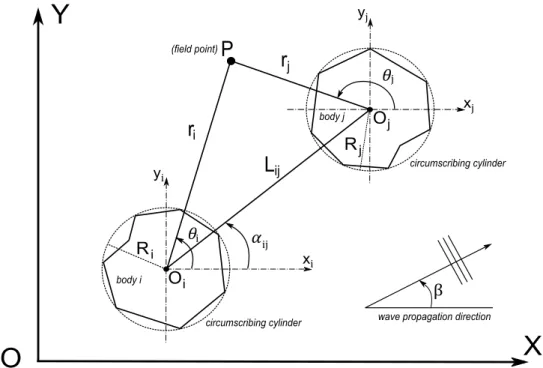
2.3 Incident plane wave as a summation of partial cylindrical waves plot-ted as the surface elevation for increasing truncation values M. Source: McNatt et al. (2015). . . 26 2.4 Schematic of the plane view of two bodies of arbitrary geometry with
the nomenclature and reference systems used herein. . . 28 3.1 Authorized a) and unauthorized b) relative position between bodies
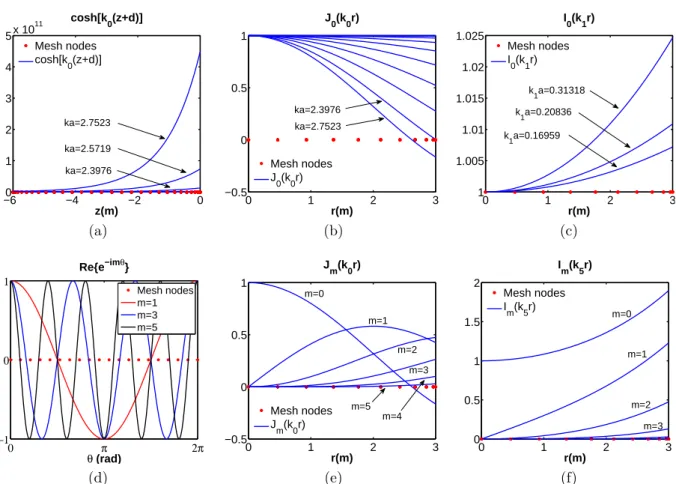
when using the Direct Matrix Method interaction theory. Source: adapted from Chakrabarti (2001). . . 48 3.2 Variation of the hyperbolic cosine depth dependence (a), the Bessel
function of the first kind (b, e) and the modified Bessel function of the first kind (c, f) along the lateral side and the bottom of a cylinder respectively (3m radius, 6m draft in a 30m water depth). Results in (e) are calculated for k0a= 2.7523 and in (f) for k5a= 1.7279. Variation of
the sinusoindal term e−imθ along the perimeter of the cylinder (d). Red
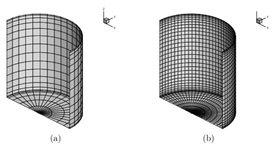
points represent the nodes of a given mesh . . . 53 3.3 Truncated vertical cylinder mesh. Only half of the geometry is shown
due to symmetry. (a) - coarse mesh, 361 panels; (b) - fine mesh 1521 panels. . . 54
xvi List of Figures 3.4 Cube mesh. Only half of the geometry is shown due to symmetry. (a)
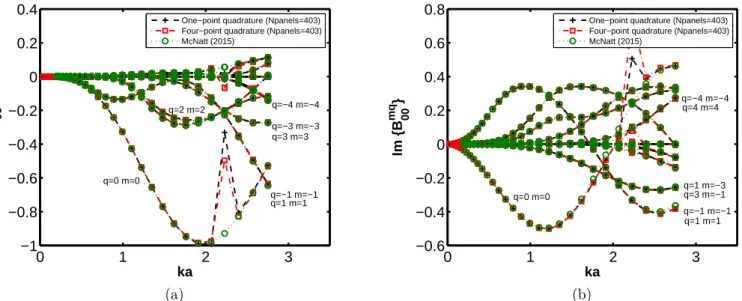
- coarse mesh, 403 panels; (b) - fine mesh 2059 panels. . . 54 3.5 Real and imaginary parts of the Diffraction Transfer Matrix progressive
terms for a truncated vertical cylinder of 3m radius (a), 6m draft in a 10m water depth. . . 55 3.6 Real and imaginary parts of the Diffraction Transfer Matrix progressive
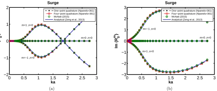
terms for a cube of 6m side (2a), 6m draft in a 10m water depth. . . . 56 3.7 Real and imaginary parts of the Radiation Characteristics progressive
terms for a truncated vertical cylinder of 3m radius (a), 6m draft moving in surge in a 10m water depth. . . 57 3.8 Real and imaginary parts of the Radiation Characteristics progressive
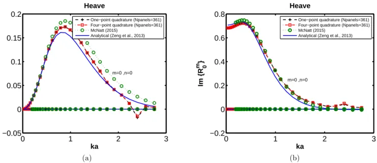
terms for a truncated vertical cylinder of 3m radius (a), 6m draft moving in heave in a 10m water depth. . . 58 3.9 Real and imaginary parts of the Radiation Characteristics progressive
terms for a cube of 6m side (2a), 6m draft moving in surge in a 10m water depth. . . 59 3.10 Real and imaginary parts of the Radiation Characteristics progressive
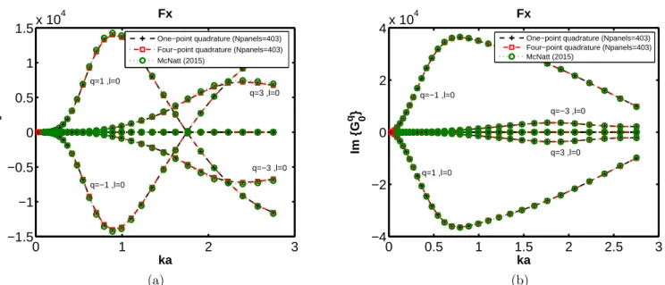
terms for a cube of 6m side (2a), 6m draft moving in heave in a 10m water depth. . . 60 3.11 Real and imaginary parts of the Force Transfer Matrix progressive Fx
terms for a truncated vertical cylinder of 3m radius (a), 6m draft in a 10m water depth. . . 61 3.12 Real and imaginary parts of the Force Transfer Matrix progressive Fz
terms for a truncated vertical cylinder of 3m radius (a), 6m draft in a 10m water depth. . . 61 3.13 Real and imaginary parts of the Force Transfer Matrix progressive Fx
terms for a cube of 6m side (2a), 6m draft in a 10m water depth. . . . 62 3.14 Real and imaginary parts of the Force Transfer Matrix progressive Fz
terms for a cube of 6m side (2a), 6m draft in a 10m water depth. . . . 62 3.15 Real and imaginary parts of the Force Transfer Matrix progressive Mz
4.1 Schematic of the domains used for the application of the Green’s the-orem. Free surface (SL); body’s wetted surface (Sb); body’s
circum-scribing cylinder radius (Rc); cylindrical surface infinitesimally larger
than the body’s circumscribing cylinder (Sϵ
c), seabed (F ); limit of the
domain at infinity (S∞); domain interior to the circumscribing cylinder
(Ωint); domain comprised between the circumscribing cylinder and the
cylindrical surface at infinity (Ωout). . . 68
4.2 Real (a) and Imaginary (b) parts of the FTM progressive terms in the surge (k=1) degree of freedom for an isolated cylinder of radius a, draft (d − h = 2a) in a water depth (d = 4a). The solid line (direct) corresponds to the direct calculation of the FTM using NEMOH. The dotted line (indirect) is obtained from the RC computed with NEMOH and by using the right-hand side of equation (4.1.39). . . 82
4.3 Real (a) and Imaginary (b) parts of the FTM progressive terms in the Roll (k=4) degree of freedom for an isolated cylinder of radius a, draft (d − h = 2a) in a water depth (d = 4a). The solid line (direct) corresponds to the direct calculation of the FTM using NEMOH. The dotted line (indirect) is calculated from the RC computed with NEMOH and by using the right-hand side of equation (4.1.39). . . 82
4.4 Diagonal radiation damping coefficients for the degrees of freedom Surge (a) and Roll (b) of a cylinder of radius a, draft (d − h = 2a) in a water depth (d = 4a). The solid line (direct) corresponds to the direct calculation of the damping coefficients using NEMOH. The dotted line (indirect) is calculated from the RC computed with NEMOH and by using the right-hand side of equation (4.1.58). . . 83
4.5 Schematic representation of an array composed of four truncated ver-tical cylinders of radius a and separated by a distance between centers
xviii List of Figures 4.6 Non-dimensional excitation forces in Surge (a) and Heave (b) for the
cylinders 1-2 in the array shown in Figure 4.5 from an incident plane wave with propagation direction (β = 0) and amplitude A . The solid line reproduces the results by Siddorn and Eatock Taylor (2008); the dotted green line has been computed with the IT by Kagemoto and Yue (1986) using NEMOH to compute the required hydrodynamic operators and the dotted blue line by means of the right-hand side of the extended cylindrical Haskind relation (4.2.12). The black dotted lines (−·−·) and (····) correspond respectively to the contribution to the total excitation force from the isolated body and from the hydrodynamic interactions with the neighbours and have been computed from the first and second terms of equation (4.2.13) respectively. . . 84 4.7 Non-dimensional excitation forces in Surge (a) and Heave (b) for the
cylinder 1 in the array shown in Figure 4.5 from an incident plane wave with propagation direction (β = π/4) and amplitude A . The legend follows as in Figure 4.6. . . 85 4.8 Non-dimensional Surge coupling radiation damping coefficients between
two cylinders (1-3 in a); 1-4 in b)) in the array shown in Figure 4.5. The first index indicates the cylinder on which the radiation force is evalu-ated due to the motion of the body indicevalu-ated by the second index. The solid line reproduces the results by Siddorn and Eatock Taylor (2008); the dotted green line has been computed with the IT by Kagemoto and Yue (1986) using NEMOH to compute the required hydrodynamic operators and the dotted blue line by means of the right-hand side of equation (4.2.3). . . 86 4.9 Non-dimensional Heave coupling radiation damping coefficients between
two cylinders (1-3 in a); 1-4 in b)) in the array shown in Figure 4.5. The legend follows as in Figure 4.8. . . 87 4.10 Non-dimensional Heave-Surge coupling radiation damping coefficients
between two cylinders (1-3 in a); 1-4 in b)) in the array shown in Figure 4.5. The legend follows as in Figure 4.8. . . 87
4.11 Non-dimensional diagonal Surge (a) and Heave (b) radiation damping coefficients of cylinder 1 in the array shown in Figure 4.5. The solid line reproduces the results by Siddorn and Eatock Taylor (2008); the dotted green line has been computed with the IT by Kagemoto and Yue (1986) using NEMOH to compute the required hydrodynamic operators and the dotted blue line by means of the right-hand side of equation (4.2.3). The black dotted lines (−·−·) and (····) correspond respectively to the contribution to the total radiation force from the isolated body and from the hydrodynamic interactions with the neighbours and have been computed from the first and second terms of equation (4.2.20) respectively. . . 88 4.12 Schematic of an array composed of two truncated vertical cylinders.
β = 0 corresponds to the positive x − axis. . . 89
4.13 Added mass and damping coefficients for the first truncated vertical cylinder (3m radius, 6m draft in a 50m water depth) in the two body array (Figure 4.12) for different separating distances (d/a = 5000 - (a),
d/a = 5 - (b), d/a = 5 - (c)). First index corresponds to the direction
of the force and the second to the degree of freedom. . . 90 4.14 Heave-heave coupling added mass coefficient as a function of the
evanes-cent modes truncation L and for a small array of two truncated vertical circular cylinders of radius 3m, draft 6m in water depth of 50m. . . 91 4.15 Surge-surge coupling added mass coefficient as a function of the
evanes-cent modes truncation L for two different wavelengths for a small array of two truncated vertical circular cylinders of radius 3m, draft 6m in water depth of 50m. . . 91 4.16 Magnitude of surface elevation for an array of 4 cylinders of 3m
ra-dius, 6m draft in a 50m water depth with a separation distance of 12m. Plots c, d, e, f show the percentage difference between the wave fields computed with the interaction theory (b) indicated by IT and the di-rect calculation using NEMOH (a) indicated by N as a function of the evanescent modes truncation L ((c) - L = 0, (d) - L = 6, (e) - L = 12, (f) - L = 18). Results are normalized by the amplitude of the incident wave (A). Propagation direction is defined from left to right. . . 93
xx List of Figures 4.17 Magnitude of surface elevation for an array of 4 cube boxes of 6m side,
6m draft in a 50m water depth with a separation distance of 12m. Plots c, d, e, f show the percentage difference between the wave fields computed with the interaction theory (b) indicated by IT and the di-rect calculation using NEMOH (a) indicated by N as a function of the evanescent modes truncation L ((c) - L = 0, (d) - L = 6, (e) - L = 12, (f) - L = 18). Results are normalized by the amplitude of the incident wave (A). Propagation direction is defined from left to right. . . 94 4.18 Condition number of the system scattering matrix of a 4 cylinder array
(without Bessel functions normalization). . . 96 4.19 Condition number of the system scattering matrix of a 4 cylinder array
(with Bessel functions normalization). . . 97 4.20 Schematic of an array of inline bodies separated by a distance d. . . 99 4.21 Discretization of a) a truncated vertical cylinder of 3m radius and 6m
draft, b) a flap-type converter of 6m width by 2m side. . . 100 4.22 Comparison of wall clock computational times between the Direct
Ma-trix Method interaction theory (IT) and direct NEMOH simulations for both a truncated vertical cylinder a) and a flap-type converter b), shown respectively in Figures 4.21a and 4.21b, as a function of the num-ber of bodies positioned successively in line and separated by a distance of 60 meters. Calculations using the interaction theory require, first, the evaluation of the isolated body hydrodynamic characteristics and, then, the solution to the multiple scattering problem. The time associ-ated with the former is indicassoci-ated as “HC” and with the latter as “IT”. The evanescent modes truncation is referred to as “L”. Simulations were performed with 6 dofs per body, 30 frequencies (0.2 - 2.0 rad/s) and 5 propagation directions and both the diffraction and radiated problems were solved. . . 101 4.23 Curve fitting of the wall clock computational time of direct NEMOH
simulations for both a truncated vertical cylinder a) and a flap-type converter b) shown in Figures 4.21a and 4.21b respectively. . . . 102 5.1 Top (a) and Side (b) schematic views of the bottom-referenced
5.2 Response Amplitude Operator (RAO) and power function of an indi-vidual isolated hemispherical float as a function of the Power Take-Off damping (Bpto) and for both a range of incoming wave frequencies and
directions. . . 114 5.3 (a) Top view of a section of a three-float WEC; (b) Comparison of the
Response Amplitude Operator (RAO) of float 2 computed using both a direct BEM calculation (both when isolated and in array) and with the Direct Matrix Method interaction theory (IT ) using 4 evanescent modes (L) and a β = 90◦ wave incidence; (c) relative difference between the
(RAO) of float 2 computed using both a direct BEM calculation and with the Direct Matrix Method interaction theory (IT ) for different values of the evanescent modes truncation (L) and a wave incidence of
β = 90◦. . . 116
5.4 Float interaction factors (q-factor) of the bottom-fixed heave-buoy array WEC and disturbance coefficient (Hs/HsI) of the wave field for a sea
state with (Hs= 0.75m, Tp = 4s) and two mean propagation directions
(0 and π/3 rad) of the incident wave spectra. . . 118 5.5 Annual power (Py) and separating distance between floats (dx) as a
function of the number of units used in the bottom-referenced heave-buoy array WEC for two main propagation directions of the incident wave spectra. The annual power has been computed using the opti-mized separating distance (dx opt) between floats for each configuration comprised between the limits (dx max) and (dx min). . . 121 5.6 Float interaction factors (q-factor) of the 36-unit bottom-referenced
heave-buoy array WEC and disturbance coefficient (Hs/HsI) of the wave
field for a sea state with (Hs = 0.75m, Tp = 4s) and two mean
propa-gation directions (0 and π/3 rad) of the incident wave spectra. . . 124 5.7 Float significant motions (γs) of the 60 and 36-unit bottom-referenced
heave-buoy array WEC for the sea state with (Hs = 2.75m, Tp = 6.44s)
and two mean propagation directions (0 and π/3 rad) of the incident wave spectra. . . 125
xxii List of Figures 5.8 Annual power (Py) produced by a 36-unit bottom-referenced heave-buoy
array WEC as a function of both the radius of the hemispheric floats and the value of PTO damping (Bpto) used for two main propagation
directions of the incident wave spectra (β). The values of PTO damping optimized for each float radius of the 36-unit configuration are indicated as (Br
pto,36) whereas (Bpto,60r=3m) refers to the PTO damping which optimizes
the annual power produced by the 60-unit configuration with 3m radius floats. . . 127 5.9 Float significant motions (γs) of the 36-unit bottom-referenced
heave-buoy array WEC with float radius 4.5m for the sea state with (Hs =
2.75m, Tp = 6.44s) and two mean propagation directions (0 and π/3 rad)
of the incident wave spectra. Results are presented for two different val-ues of PTO damping (Br=3m
pto,60) and (Bpto,36r=4.5m). The former is optimized to
maximize the energy capture of a 60-unit configuration with 3m radius floats and the latter of a 36-unit with 4.5m radius floats. . . 129 6.1 Schematic of the coupling between the IT and a Spectral wave model.
Filled circles represent the array WECs whereas the empty ones the scattered and radiated wave fields given as a superposition of cylindrical harmonics by the IT (Kagemoto and Yue, 1986). Sin and Soutrepresent
both the incident and transmitted spectra at the inlet and outlet of the wave farm respectively indicated as dotted lines. . . 132 6.2 Schematic of the integration contours in the complex χ plane. The
arrows indicate direction. . . 135 6.3 Influence of the truncation parameter γ on the evaluation of the Hankel
function of the first kind for the case x ≥ 0 and with r = x (θ = 0). When only a single line is visible it means that a perfect match of results is obtained. . . 137 6.4 Schematic representation of the cylindrical harmonics transformation
into plane waves in the horizontal plane. (xj, yj) represent the
sian reference system local to body j and OXY the global Carte-sian reference system in which the jth body center Oj is expressed
Oj = (X0j, Y0j). ξ0 and ξ1 are vertical planes parallel to the y axis and
containing the centers of all the bodies in the array. . . 140 6.5 Schematic of three and two truncated vertical cylinder array
6.6 Transmission a) and reflection b) coefficient as a function of the angu-lar variable sampling Nt for an array of 3 truncated vertical cylinders
disposed parallel to the Y axis as in Figure 6.5a and with d/a = 4 . . . 148 6.7 Number of angular discretization samples Nt as a function of the
sep-arating distance between bodies d for both the transmission a) and reflection b) coefficients of an array of 3 truncated vertical cylinders as shown in Figure 6.5a. . . 148 6.8 Transmitted a) and reflected b) coefficients for an array of both 3 and
51 cylinders displayed parallel to axis Y as shown in Figure 6.5a. . . 149 6.9 Sensitivity of the angular variable discretization on the transmission a)
and reflection b) coefficients as a function of the wave length to satisfy (6.2.6) with a precision of 10−5 . . . 150
6.10 Reflected a) and transmitted b) energy spectra of the scattered wave field for a two cylinder array with separating distance d = 6a between bodies with a the cylinder radius. The wave forcing is as in (6.4.1) with a wave length λ/a = 10. . . 151 6.11 Reflected a) and transmitted b) energy spectra of the radiated wave
field for a two cylinder array with separating distance d between bodies with a the cylinder radius. The wave forcing is as in (6.4.1) with a wave length λ/a = 10. . . 151 6.12 Sensitivity study of the improper integral truncation parameter γ on the
scattered free surface elevation (η). Plots on the left column (a, c, e) represent the absolute value of the scattered free surface elevation; right column (b, d, f) show the difference in percentage between the free surface elevation computed with the interaction theory (ηIT) and with
the transformation of cylindrical harmonics to plane waves (ηP C). The
incident wave forcing is as in (6.4.1) and the wave length λ/a = 10. . . 153 6.13 Sensitivity study of the improper integral truncation parameter γ on
the radiated free surface elevation (η). Plots on the left column (a, c, e) represent the absolute value of the scattered free surface elevation; right column (b, d, f) show the difference in percentage between the free surface elevation computed with the interaction theory (ηIT) and with
the transformation of cylindrical harmonics to plane waves (ηP C). The
incident wave forcing is as in (6.4.1) and the wave length λ/a = 10. . . 154 B.1 Authorized a) and unauthorized b) relative position between bodies to
xxiv List of Figures C.1 Coordinate system. Source: Sabuncu and Calisal (1981) . . . 184 C.2 . . . 187 C.3 . . . 188 C.4 . . . 188 C.5 . . . 189 C.6 . . . 189 C.7 . . . 190 C.8 . . . 192 C.9 . . . 193 C.10 . . . 194 C.11 . . . 195 C.12 . . . 196 C.13 . . . 197 C.14 Bessel functions of the first kind and second kind (a); Modified Bessel
functions of the first and second kind (b). Source: Abramowitz and Segun A. (1964) . . . 199 D.1 Source: adapted from Zeng and Tang (2013) . . . 207 D.2 . . . 249 D.3 . . . 250 D.4 . . . 250 D.5 . . . 251 D.6 . . . 252 D.7 . . . 253 D.8 . . . 254 D.9 . . . 255 D.10 . . . 256 D.11 . . . 257 D.12 Comparison between diagonal added mass and damping coefficients for
two cylinders (Figure D.6b) of radius 3m, draft 6m in a 10m water depth at several separation distances and for several truncation values (represented as L). First index corresponds to the direction of the force and the second to the degree of freedom. . . 259
D.13 Comparison between diagonal added mass and damping coefficients for two cylinders (Figure D.6b) of radius 3m, draft 6m in a 10m water depth at several separation distances and for several truncation values (represented as L). First index corresponds to the direction of the force and the second to the degree of freedom. . . 260 D.14 Comparison between diagonal added mass coefficients computed with
NEMOH, with the IT and a semi-analytical solution for two truncated vertical cylinders (Figure D.6b) of radius 3m, draft 6m in a 10m water depth at several separation distances. First index corresponds to the direction of the force and the second to the degree of freedom. . . 261 D.15 Comparison between diagonal added mass coefficients computed with
NEMOH, with the IT and a semi-analytical solution for two truncated vertical cylinders (Figure D.6b) at several separation distances. First index corresponds to the direction of the force and the second to the degree of freedom. . . 262 D.16 Diagonal and coupled added-mass and damping radiation coefficients in
heave for two truncated vertical cylinders (Figure D.6b) as a function of the frequency. Two sets of results computed with a semi-analytical solution and with the IT are presented. The bodies have a radius of 5m, a 10m draft in 50m water depth and are separated by 200m. First index corresponds to the direction of the force and the second to the degree of freedom. . . 263 F.1 Real and imaginary parts of the Diffraction Transfer Matrix progressive
terms for a truncated vertical cylinder of 3m radius (a), 6m draft in three different water depths. For 30m the Green’s function constant used is in its original form. . . 272 F.2 Real and imaginary parts of the Diffraction Transfer Matrix progressive
terms for a truncated vertical cylinder of 3m radius (a), 6m draft in three different water depths. For all water depths the Green’s function constant has been reformulated. . . 273 G.1 Points of quadrature for a multidimensional integration. The square
has limits |x| ≤ h, |y| ≤ h whereas the triangle is inscribed in a circle of radius h. Source: Abramowitz and Segun A. (1964) . . . 276 G.2 Four node bilinear quadrilateral and its image in parametric space.
xxvi List of Figures G.3 Interpolation functions for node 1 of a quadrilateral element. Source:
adapted from Felippa (2014) . . . 277 G.4 Red numbers indicate node number and the limits of the domain are
indicated in italic. Adapted from: Topper (2010) . . . 278 I.1 Real and imaginary parts of the Diffraction Transfer Matrix progressive
terms for a truncated vertical cylinder of 3m radius (a), 6m draft in a 10m water depth. . . 291 I.2 Real and imaginary parts of the Radiation Characteristics progressive
terms for a truncated vertical cylinder of 3m radius (a), 6m draft moving in surge in a 10m water depth. . . 292 I.3 Real and imaginary parts of the Radiation Characteristics progressive
terms for a truncated vertical cylinder of 3m radius (a), 6m draft moving in heave in a 10m water depth. . . 292 I.4 Real and imaginary parts of the Radiation Characteristics progressive
terms for a truncated vertical cylinder of 3m radius (a), 6m draft moving in pitch in a 10m water depth. . . 293 I.5 Real and imaginary parts of the Diffraction Transfer Matrix progressive
terms for a square box of 6m side (2a), 6m draft in a 10m water depth. 293 I.6 Real and imaginary parts of the Radiation Characteristics progressive
terms for a square box of 6m side (2a), 6m draft moving in surge in a 10m water depth. . . 294 I.7 Real and imaginary parts of the Radiation Characteristics progressive
terms for a square box of 6m side (2a), 6m draft moving in heave in a 10m water depth. . . 294 I.8 Real and imaginary parts of the Radiation Characteristics progressive
terms for a square box of 6m side (2a), 6m draft moving in pitch in a 10m water depth. . . 295 I.9 Real and imaginary parts of the Radiation Characteristics progressive
terms for a truncated vertical cylinder of 3m radius (a), 6m draft moving in sway in a 10m water depth. . . 295 I.10 Real and imaginary parts of the Radiation Characteristics progressive
terms for a truncated vertical cylinder of 3m radius (a), 6m draft moving in roll in a 10m water depth. . . 296 I.11 Real and imaginary parts of the Radiation Characteristics progressive
terms for a truncated vertical cylinder of 3m radius (a), 6m draft moving in pitch in a 10m water depth. . . 296
I.12 Real and imaginary parts of the Radiation Characteristics progressive terms for a square box of 6m side (2a), 6m draft moving in sway in a 10m water depth. . . 297 I.13 Real and imaginary parts of the Radiation Characteristics progressive
terms for a square box of 6m side (2a), 6m draft moving in roll in a 10m water depth. . . 297 I.14 Real and imaginary parts of the Radiation Characteristics progressive
terms for a square box of 6m side (2a), 6m draft moving in pitch in a 10m water depth. . . 298 I.15 Real and imaginary parts of the Force Transfer Matrix progressive Fy
terms for a truncated vertical cylinder of 3m radius (a), 6m draft in a 10m water depth. . . 299 I.16 Real and imaginary parts of the Force Transfer Matrix progressive Mx
terms for a truncated vertical cylinder of 3m radius (a), 6m draft in a 10m water depth. . . 299 I.17 Real and imaginary parts of the Force Transfer Matrix progressive My
terms for a truncated vertical cylinder of 3m radius (a), 6m draft in a 10m water depth. . . 300 I.18 Real and imaginary parts of the Force Transfer Matrix progressive Fy
terms for a square box of 6m side (2a), 6m draft in a 10m water depth. 300 I.19 Real and imaginary parts of the Force Transfer Matrix progressive Mx
terms for a square box of 6m side (2a), 6m draft in a 10m water depth. 301 I.20 Real and imaginary parts of the Force Transfer Matrix progressive My
terms for a square box of 6m side (2a), 6m draft in a 10m water depth. 301 I.21 Real and imaginary parts of the Force Transfer Matrix progressive Mz
terms for a square box of 6m side (2a), 6m draft in a 10m water depth. 302 J.1 Diagonal and off-diagonal terms of the added-mass coefficient matrix
A(equation 5.1.3) of the three-float system representing part of the generic bottom-fixed heave-buoy array WEC studied in Chapter 5. . . 305 J.2 Diagonal and off-diagonal terms of the hydrodynamic damping
coef-ficient matrix B (equation 5.1.3) of the three-float system represent-ing part of the generic bottom-fixed heave-buoy array WEC studied in Chapter 5. . . 306 J.3 Terms of the excitation moment vector Mex (equation 5.1.3) of the
three-float system representing part of the generic bottom-fixed heave-buoy array WEC studied in Chapter 5 for a wave incidence of β = 90◦. 307
xxviii List of Figures J.4 (a) Top view of a section of a three-float WEC with no Power
Take-Off (PTO); (b) Comparison of the Response Amplitude Operator (RAO)
of float 2 computed using both a direct BEM calculation (both when isolated and in array) and with the Direct Matrix Method interaction theory (IT ) using 4 evanescent modes (L) and a β = 90◦ wave incidence;
(c) relative difference between the (RAO) of float 2 computed using both a direct BEM calculation and with the Direct Matrix Method interac-tion theory (IT ) for different values of the evanescent modes truncainterac-tion (L) and a wave incidence of β = 90◦. . . 308
4.1 Size of the Boundary Value Problem to be solved using both a direct NEMOH simulation and the interaction theory (IT) for different values of evanescent modes truncation (L). The highest and lowest truncation levels required for the IT in the frequency range of the case study are indicated as ITmax and ITmin respectively. The problem size is defined
based on the discretizations of two different geometries, a truncated vertical circular cylinder and a flap-type converter shown in Figures 4.21a and 4.21b respectively. . . 100 5.1 Main parameters of the bottom-referenced heave-buoy array Wave
En-ergy Converter. . . 109 5.2 Main parameters of an hemispheric float. . . 110 5.3 Wave climate series used in the simulations. . . 113 5.4 Influence of the evanescent modes truncation on the power generated. . 119 5.5 Comparison of wall clock execution time between the IT and direct
NEMOH calculations for each of the optimized configurations in Fig-ure 5.5. The execution time of the direct BEM simulations has been estimated following the procedure detailed in section 4.3.4. . . 122 C.1 Comparison between analytical and numerically calculated values (ω =
Chapter 1
Introduction
1.1
Context
The reduction of greenhouse gas emissions, whose influence on global warming and climate change is clear (IPCC, 2014), has been set as a top priority for all the world countries. In December 2015, the first international climate agreement to limit tem-perature rise below 2◦C was signed in the 21st annual session of the Conference of the
Parties (COP) to the UN Framework convention on Climate Change (COP21, 2015). According to the Intergovernmental Panel on Climate Change (IPCC, 1988), global warming of more than 2◦C would have important negative consequences for the planet,
such as a global mean sea level rise and the increase in the number of extreme events like heat waves and strong precipitation (IPCC, 2014).
Although the use of renewable energy is rising, the process of transitioning away from fossil fuels has still a long way to go. Indeed, the estimated renewable energy share of global final energy consumption was of 19.2% in 2014, and of 23.7% when considering only the share of global electricity production (REN21, 2016). Of this latter total share, the highest contribution was from hydropower (16%) in contrast with the combination of geothermal, concentrated solar power and ocean energies which only accounted for 0.4%.
In spite of its small weight from a global scale perspective, ocean energy is expected to represent a significant part of the European Union’s (EU) power mix. According to SI Ocean (2014), it is estimated that by 2050 wave and tidal energy alone could gen-erate 10% of the EU’s power demand through the deployment of 100GW of capacity. To reach this scenario, the cost of the electricity generated from these technologies ought to be significantly reduced. According to SI Ocean (2013), the lowest estimated cost of electricity produced by the first pilot 10MW arrays could orbit around the
0.35c€/kWh. However, to be competitive, the targeted cost should be 0.10c€/kWh or lower (TPOcean, 2016). This means that a reduction of the cost by at least a factor 3 is to be achieved.
In order to accomplish this ambitious target, the EU has identified a set of priority areas for R&I in what is referred to as the first ever European Strategic Research Agenda for ocean energy (TPOcean, 2016). The objective of the present work, whose main focus is exclusively on wave energy, is aligned with one of them which seeks the
creation of numerical models that optimise computational power (priority
area 1.2 part C).
To successfully develop wave energy converters (WECs) it is common practice (Cruz, 2008) to conduct numerical studies, at an early-stage and under simplified and rather idealized conditions, to assess the performance of the technology and to intro-duce, if required, modifications to the initial WEC design. Outputs from numerical models shall then be validated through experimental testing campaigns. The combina-tion of both approaches enables one to check whether important physical phenomena have been omitted by the computational package and to feed back real experimental data to the numerical model to improve it further.
As opposed to other renewable energy technologies, such as wind turbines, con-vergence to a single or a reduced number of WEC designs has not yet been achieved. Indeed, Falcão (2010) states that more than a thousand patents had been registered by 1980 and that this number has significantly grown since then. In an attempt to or-ganize the ensemble of WEC technologies, several classifications have been proposed. The subject is vast and the interested reader is encouraged to refer to dedicated re-views on the topic (Falcão, 2010; Pecher and Kofoed, 2017). Succinctly, based on the principle of operation one can distinguish amongst oscillating water columns, oscillat-ing bodies and overtopposcillat-ing devices. With respect to their size, if they are small in comparison with the incident wave length they are referred to as point absorbers, in contrast with large absorbers. In addition, if their characteristic dimension is aligned with the main wave propagation direction they are categorized as attenuators and as terminators when they are oriented parallel to the wave crests.
As a consequence of the great variety of solutions proposed to extract power from ocean waves, dedicated numerical modeling tools adapted to each WEC need to be developed. The study by Babarit et al. (2012a) on the numerical modeling of an electro-active deformable wave energy converter or the review by Falcao and Henriques (2016) on oscillating water column technology are recent illustrative examples. For a more general review the reader should refer to the study by Babarit et al. (2012b) who
1.1 Context 3
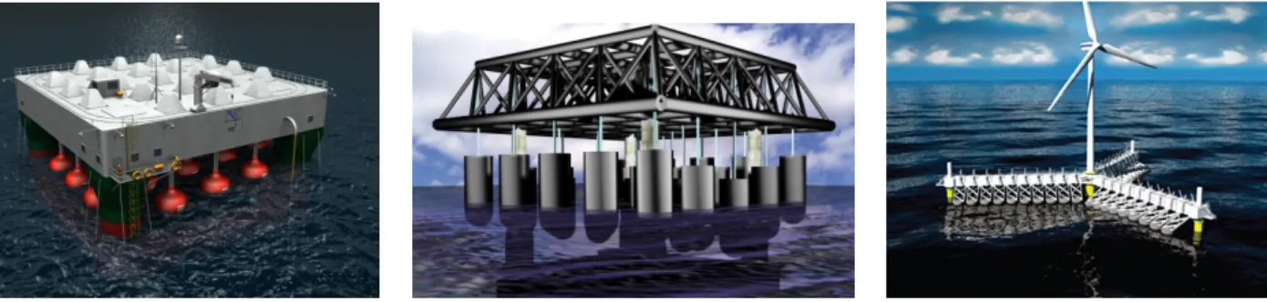
(a) Source: Fred Olsen Ltd (2009) (b) Source: Manchester Bobber (2008) (c) Source: WAVESTAR (2015) Figure 1.1: Three examples of multi-body WECs. a) F O3 platform, b) Manchester
Bobber, c) Wavestar SC-Concept
presented the numerical modeling of a selection of eight WECs with different working principles in an attempt to derive general trends of performance amongst the different converter categories.
The focus of this work is on the hydrodynamic numerical modeling of compact arrays of small wave absorbers, referred as well to as multi-body WECs, which consti-tutes one of the examples of the existing categories of WECs and have been identified as being an advantageous solution when compared to a big isolated point absorber (Garnaud and Mei, 2009). Examples of this type of converters include the F O3
plat-form (Taghipour and Moan, 2008), the Manchester Bobber (Weller et al., 2010) and the Wavestar (Hansen and Kramer, 2011) which are depicted in Figure 1.1. Amid the numerous challenges associated with the numerical modeling of such devices, the most relevant one at the time of the present study is the computation of the hydrodynamic interactions amongst the large number of floats (> 20) they are composed of.
Certainly, numerical models conceived for the preliminary investigation of WEC power capture need to be accurate and have as low computational cost as possible. The latter is fundamental given that the predictions of power production on a site are to be computed over long periods of time, typically a year, and that the optimization of the device requires multiple evaluations of the annual energy absorption for each different geometrical parameter set.
Because of that, one of the most common approaches to study the wave-structure interactions in the context of wave energy conversion consists in linearizing the prob-lem by assuming both a small wave steepness and small body motions and in adopting a perfect inviscid fluid model. These hypotheses enable one to use a relatively
sim-ple formulation, referred to as Boundary Element Method (BEM), associated with a remarkable calculation speed and with sufficiently accurate results for the targeted applications. Over the past decades, several BEM solvers have been developed for seakeeping computations (WAMIT (Lee and Newman, 1999), ANSYS Aqwa (AN-SYS Aqwa, 2016), AQUAPLUS (Delhommeau, 1987), DIODORE (Principia, 2016), HYDROSTAR (Bureau Veritas, 2016), etc.) amongst which only one, developed at Ecole Centrale de Nantes and known as NEMOH (Babarit and Delhommeau, 2015), is available as open source since 2014.
In spite of its gain in computational speed with respect to other approaches, such as Computational Fluid Dynamics (CFD), the study of the hydrodynamic interactions with BEM solvers is hampered by an increase of the number of bodies considered. The fact that they solve the diffraction problem for all bodies simultaneously and given that all wetted parts need to be discretized leads to a very large system of equations. Indeed, for cases involving clusters of say O(100) floats, the increase in computational time precludes the direct simulation of such systems and their optimization.
Driven by this limitation, a set of alternative numerical modeling strategies have been proposed and are reviewed in the following section.
1.2
State-of-the-art
The challenges associated with the hydrodynamic modeling of a multi-body WEC composed of a large number of floats are analogous to those faced in the study of the park effect in large wave farms. The latter refers to the modification of the total power that a group of isolated WECs would absorb as a consequence of the wave interactions that deploying them in relatively close proximity gives rise to.
Numerous investigations on the park effect in WEC arrays have been conducted over the past years. In the following paragraphs, the numerical modeling techniques used to compute it will be reviewed. In addition, the approaches adopted to deal with the hydrodynamic interactions in other contexts, such as in the design of very large floating structures, will also be addressed.
In spite of the obvious similarities in the study of the multiple-scattering of waves in large clusters of bodies, such as a large WEC array and a multi-body WEC, there exist important differences between them as far as the magnitude of the wave interaction effects is concerned. The latter are clearly more important amongst closely spaced bodies. In fact, the review by Babarit (2013) on the park effect research conducted over the past 30 years concluded that, provided the separating distance between the devices
1.2 State-of-the-art 5 (typically of 10−20m size) is on the order of ∼ 100−200 meters, the interaction effects computed based on irregular waves cannot be considered to be significant. While this is true for small arrays of less than ∼ 10 devices, the author adds that for larger arrays the number of rows (perpendicular to the main incident wave direction) should be kept as limited as possible to reduce destructive interaction effects.
The most common and generic approach to deal with WEC array interactions is to use BEM solvers which can account for the specificities of each WEC geometry and the bodies interdistances without restrictions. Not surprisingly, the majority of the studies conducted on multi-body WECs composed of O(20) floats such as the ones shown in Figures 1.1a and 1.1b (De Backer et al., 2010; Taghipour and Moan, 2008) and further analyzed in Chapter 5, have used a BEM to compute the hydrodynamic interactions. As of reminder, BEM solvers are built upon linear potential wave theory and, therefore, linearity of the governing equations and perfect fluid characteristics are assumed. The former implies a small wave steepness and a small amplitude of the body motions with respect to its characteristic dimensions. As stated in Folley et al. (2012), these hypotheses are usually satisfied in small to moderate sea states where good agreement between BEM output and results from more accurate models such as CFD is obtained. Significant discrepancies are obtained for larger sea states though.
Besides the inherent assumptions involved in the use of potential flow theory, the most limiting factor of BEM codes for the study of WEC interactions is the increase of the numerical complexity as a function of the square of the number of unknowns. In BEM solvers based on low-order methods, such as NEMOH , these are equal to the number of panels used to discretize the wetted surface of the bodies. In other solvers, such as WAMIT, computations can be performed using a higher-order method where the number of unknowns depends as well on the order of the basis functions.
In his attempt to derive initial guidelines for the design of wave farms, Babarit (2013) points out the contrast between the great amount of published works on the park effect of rather small arrays and the few studies available for larger wave farms. One of them was carried out recently by Borgarino et al. (2012b) who implemented a
Fast Multipole Method (FMM) (Borgarino et al., 2012a) to accelerate the
simu-lations of large WEC farms with the BEM solver AQUAPLUS (Delhommeau, 1993). This implied the extension of the infinite-depth free-surface Green’s function multi-pole expansion to be used in a three-dimensional algorithm. The same development is expected to be applicable to the finite-depth formulation but was not attempted in Borgarino (2011). The author reported difficulties in the convergence of the multipole expansion for relatively small wave periods and therefore implemented a simplified
version of the FMM suited specifically to the modeling of wave farms. Other tech-niques, such as pre-corrected Fast Fourier Transforms (FFT), have been used to accelerate BEM computations (Kring et al., 2000) but have some limitations when dealing with sparse arrays (Singh and Babarit, 2014).
While the use of BEM solvers provides an exact solution to the multiple-scattering problem of wave interactions in array, in certain circumstances approximations can be introduced to obtain significant computational savings through a reduction of the problem complexity. Analytical developments in the early works on the park effect in WEC arrays (Budal, 1977; Evans, 1980; Falnes, 1980) were based on such approxi-mate techniques, in particular the point absorber approximation which assumes that the characteristic dimensions of the devices in array are much smaller than the wavelength of the incident waves. This implies that the diffraction by each device can be neglected. By means of this approximation, the aforementioned studies showed that significant constructive interactions could occur within an array provided that the layout of the converters was appropriately chosen.
While the early works on array interactions based on monochromatic unidirectional waves suggested exploiting the benefits of layout optimization, it was later found that the benefits of such constructive effects in irregular waves with directional spreading and with devices suboptimally controlled would be very limited. This conclusion was reached for instance in the study by Folley and Whittaker (2009) who investigated the maximum annual energy capture of a WEC array at the European Marine Energy Centre (EMEC) with a hydrodynamic model based on point absorber theory. Based on the same approximation, Fitzgerald and Thomas (2007) derived an important con-sistency condition for the array interaction factor, i.e. the ratio of the power produced by the WECs in array and the power they would produce in isolation. The relation obtained by the authors establishes that, provided the converters are optimally con-trolled, the sum of the array interaction factor for a fixed incident wave frequency over all the incident wave directions must equal unity. This means that constructive interactions occurring at specific incident wave propagation directions are balanced by destructive interactions at other wave directions.
A generalization of the identity derived by Fitzgerald and Thomas (2007) outside the zone of applicability of point absorber theory was obtained by Wolgamot et al. (2012) who showed that the sum of the maximum power absorbed by the array over all incident wave directions is proportional to the total number of degrees of freedom. As indicated by Babarit (2013), this result suggests that the multi-body WECs composed of a number of independent floats supported by a common platform, such as the ones
1.2 State-of-the-art 7 shown in Figure 1.1, might have a particularly high wave capture efficiency.
The point absorber approximation does not provide an accurate solution for the multiple-scattering problem of wave interaction in array for the whole frequency range as, by definition, it neglects the diffracted field by each device. As stated in preceding paragraphs, the solution to the full multiple-scattering problem computed by means of a direct diffraction calculation for the whole array becomes prohibitive when the number of bodies increases. Thus, alternative methods have been proposed which rely on the solution of the boundary value problem for a single isolated device. This solution is then combined with an interaction theory to account for the multiple-scattering in array. The latter involves satisfying the boundary conditions on the wetted surface of all the devices and for that two different approaches to achieve it can be distinguished. On the one hand, if the boundary conditions are imposed simultaneously to all bodies, a system of equations to be solved for the unknowns which characterize the wave fields scattered by each device is obtained. This method is generally referred to as Direct Matrix approach and was first used by Spring and Monkmeyer (1974) in the context of ocean waves to extend the solution for a single bottom mounted sur-face piercing cylinder given by MacCamy and Fuchs (1954). On the other hand, the interactions can be taken sequentially as a succession of scattering events by imposing the boundary conditions at one body at a time in what is referred to as
Multiple-Scattering method. In this case, the solution approaches the output from a Direct
Matrix approach if enough orders of scattering are considered. Intuitively, the ampli-tude of the successively scattered waves is reduced until convergence is reached. In the context of ocean waves, the first use of such approach is attributed to Ohkusu (1974) who adapted the theory by Twersky (1952) in the context of acoustics.
Both the Direct Matrix approach and the Multiple-Scattering method are applica-ble if certain spacing limitations amongst devices are satisfied, i.e. no overlapping of vertical projections is allowed and the escribed cylinder to each body cannot overlap with neighbouring devices. Apart from these restrictions, both approaches are exact provided they are applied in combination with an exact representation of the array wave fields. In some cases though, approximations can be introduced to simplify the analysis. A clear example is the work by Simon (1982) who used the Direct Matrix ap-proach in combination with a representation of the wave fields known as plane-wave
approximation which relies on two main assumptions. First, the outgoing curved
waves from each device generated by diffraction or radiation processes are modeled as being plane. Second, devices are assumed to be spaced wide enough so that the influence of the near wave field on the interactions can be neglected. The latter is
generally referred to as wide-spacing approximation.
As of reminder, the radiated or scattered wave field by a body can be decomposed into two separate contributions known generally as the far-field and the near-field. The former refers to progressive waves which carry energy to infinity as they propagate radially outward. In contrast, the latter are standing waves in the water column which have a fast decay away from the body (because of that they are usually referred to as evanescent waves) and are responsible for the transition between the fluid motion of propagating waves and that which satisfies the boundary conditions of the body geometry.
In the original work of Simon (1982) the model was restricted to axisymmetric bod-ies undergoing heave motions. McIver and Evans (1984) improved it further by adding a first correction to the plane wave expressions which relaxes the spacing requirements. More recently, Singh and Babarit (2014) coupled the BEM solver AQUAPLUS with the plane-wave approximation approach to estimate wave interaction effects in large sparse arrays of arbitrary shaped bodies.
Following the work of Ohkusu (1974), the Multiple-Scattering method was used by Mavrakos and Koumoutsakos (1987) and Mavrakos (1991) in combination with a matched eigenfunction expansion technique to solve for the Boundary Value Problem of each isolated axisymmetric body in array. In this case, and contrarily to the plane-wave approximation, evanescent modes were considered.
In spite of removing the need to store and treat simultaneously all the interactions at the same time, several authors (Kagemoto and Yue, 1986; Linton and McIver, 2001) have stated that, as the number of bodies increases, computations with the Multiple-Scattering method become impractical even for low orders of approximation and reduced number of bodies.
A comparison of the previous approximate methodologies, the point absorber and the plane-wave, and the exact multiple-scattering technique in the context of power absorption by an array of WECs was provided by Mavrakos and McIver (1997). The authors concluded that the plane-wave approximation can provide accurate results when the separating distance between devices is larger than 5 times their characteristic dimension.
In an attempt to combine the features of the Direct Matrix approach in Spring and Monkmeyer (1974) and Simon (1982), and the concept of Multiple-Scattering by Twersky (1952) and Ohkusu (1974), Kagemoto and Yue (1986) proposed an exact matrix method to solve the multiple-scattering problem. The initially unknown local wave fields at each body are characterized through a product of partial cylindrical wave
1.2 State-of-the-art 9 functions, which can account for both the near and far field contributions, and complex scattered wave coefficients which represent the amplitudes of the cylindrical wave functions. These are then transferred to the other devices by means of a transformation reminiscent of the Multiple-Scattering approach. In this case, however, the transferred wave fields represent the total converged wave fields around a body and not just one of the multiple successive scattering events. Finally, by applying this transformation which allows one to express the scattered wave field from a body as incident on the others, a system of equations is obtained and solved simultaneously as in a Direct Matrix approach.
For the use of the interaction theory by Kagemoto and Yue (1986), which solves the multiple-scattering problem by means of appropriate transformations of the isolated body solution, the latter needs to be computed in the basis of partial cylindrical wave functions. Indeed, the method makes use of a hydrodynamic operator known as diffraction transfer matrix (DTM) which mathematically characterizes the way an isolated body scatters waves by relating its incident and scattered partial complex cylindrical wave coefficients. Kagemoto and Yue (1986) only provided the way to compute it for axisymmetric geometries for which the single-diffraction solution was available on the basis of partial cylindrical wave functions.
The same approach was used by Yilmaz and Incecik (1998) who coupled the inter-action theory by Kagemoto and Yue (1986) and the single body diffrinter-action solution by Garrett (1971) to obtain analytical solutions for the diffraction problem of arrays of truncated cylinders. An extension to treat the radiation case of bodies moving as one was added in Yilmaz (1998). Using a similar strategy, Siddorn and Eatock Taylor (2008) provided extensive results for the hydrodynamic coefficients of a group of four truncated vertical cylinders set to oscillate independently and prone to near-trapped modes. Formulae for both the diffraction and radiation calculations were given within a unified framework.
In the context of the study of wave energy arrays, Child and Venugopal (2010) used an analogous approach to the one of Yilmaz to study optimal spatial configurations of heaving cylindrical wave energy converters using both a Parabolic Intersection method and a Genetic Algorithm as optimization strategies. More recently, and based on the same hydrodynamic model, Göteman et al. (2015) studied the power fluctuations of arrays of cylindrical WECs composed of O(100) bodies using a distance cut-off method, i.e. hydrodynamic interactions between two devices are only accounted for when they are separated by less than a specified distance. When using this approximation to solve the multiple-scattering diffraction problem the authors obtained a relative difference
of ∼ 3% with respect to the exact solution but an increase in computational speed of ∼45%.
The generalization of the DTM calculation for arbitrary geometries in finite-depth was derived by Goo and Yoshida (1990) who used a cylindrical representation of the Green’s function by Fenton (1978) to compute the elements of the DTM using a BEM. This approach has been used to study the forces on the fixed (Chakrabarti, 2000) and floating (Chakrabarti, 2001) modules of an interconnected multi-moduled floating offshore structure used by the US Navy. The extension to infinite-depth of both the interaction theory proposed by Kagemoto and Yue (1986) and the methodology of Goo and Yoshida (1990) was given by Peter and Meylan (2004a) who employed the former to study the interaction between ocean waves and large fields of ice floes in the marginal ice zone (MIZ).
As can be derived from the two preceding paragraphs, the application of the Di-rect Matrix method by Kagemoto and Yue (1986) to the study of the hydrodynamic interactions amongst bodies of arbitrary geometry is rather limited in contrast with the number of studies having focused on rather simple geometries such as a truncated vertical cylinder. This is fundamentally due to the difficulty in obtaining the solution for an isolated body of complex geometry in the form required by the Direct Matrix method. Indeed, the methodology by Goo and Yoshida (1990) requires the modifi-cation of the diffraction problem boundary conditions, as well as access to internal variables of the BEM code which are not part of its standard outputs.
Driven by this limitation, McNatt et al. (2015) derived an alternative strategy to compute the DTM for arbitrary geometries using the standard outputs of widely available standard BEM solvers. The method is based on a decomposition of the total velocity potential on the body’s circumscribing cylinder into partial cylindrical waves by means of a Fourier Transform (McNatt et al., 2013) and has been applied to the study of the park effect in large arrays of wave farms. Recently, the method has been embedded in the open-source numerical tool produced by the European collaborative project DTOcean (DTOcean Project, 2017) aimed at the optimization of ocean energy arrays. In addition, Sharp and DuPont (2016) used it in combination with a real-coded Genetic Algorithm to study optimal WEC array layouts which maximize power production and minimize cost. While it eliminates the need to customize the BEM solver, the method proposed by McNatt et al. (2015) to compute the DTM cannot account for evanescent modes. Thus, the subsequent multiple-scattering analysis is restrained to the wide-spacing approximation.