HAL Id: hal-01376745
https://hal.inria.fr/hal-01376745v2
Submitted on 13 Jan 2017
HAL is a multi-disciplinary open access
archive for the deposit and dissemination of
sci-entific research documents, whether they are
pub-lished or not. The documents may come from
teaching and research institutions in France or
abroad, or from public or private research centers.
L’archive ouverte pluridisciplinaire HAL, est
destinée au dépôt et à la diffusion de documents
scientifiques de niveau recherche, publiés ou non,
émanant des établissements d’enseignement et de
recherche français ou étrangers, des laboratoires
publics ou privés.
On Attitude Estimation with Smartphones
Thibaud Michel, Pierre Genevès, Hassen Fourati, Nabil Layaïda
To cite this version:
Thibaud Michel, Pierre Genevès, Hassen Fourati, Nabil Layaïda. On Attitude Estimation with
Smart-phones. IEEE International Conference on Pervasive Computing and Communications, Mar 2017,
Kona, United States. �hal-01376745v2�
On Attitude Estimation with Smartphones
Thibaud Michel, Pierre Genev`es, Hassen Fourati, Nabil Laya¨ıda
Univ. Grenoble Alpes, LIG, CNRS, GIPSA-Lab, Inria, Grenoble, France
Abstract—We investigate the precision of attitude estimation algorithms in the particular context of pedestrian navigation with commodity smartphones and their inertial/magnetic sensors. We report on an extensive comparison and experimental analysis of existing algorithms. We focus on typical motions of smartphones when carried by pedestrians. We use a precise ground truth obtained from a motion capture system. We test state-of-the-art attitude estimation techniques with several smartphones, in the presence of magnetic perturbations typically found in buildings. We discuss the obtained results, analyze advantages and limits of current technologies for attitude estimation in this context. Furthermore, we propose a new technique for limiting the impact of magnetic perturbations with any attitude estimation algorithm used in this context. We show how our technique compares and improves over previous works.
I. INTRODUCTION
Pervasive applications on smartphones increasingly rely on techniques for estimating attitude. Attitude is the orientation of the smartphone with respect to Earth’s local frame [1]. Augmented Reality (AR) applications [2], [3], [4], pedestrian dead-reckoning systems for indoor-localization [5], and photo sphere creations and previews [6] constitute examples in which precision and stability of attitude estimation matter.
Modern smartphones embed sensors such as accelerometer, gyroscope, and magnetometer which make it possible to lever-age existing attitude estimation algorithms. Such algorithms have been extensively investigated in various domains such as: robotics [7], aerospace [8], Unmanned Aerial Vehicles [9], bio-logging [10], indoor positioning [5]. However, the particular context of smartphones carried by pedestrians brings new challenges due to singular accelerations and magnetic perturbations, which sometimes invalidate the basic hypotheses that underly state-of-the-art attitude estimation algorithms. In particular, the absence of model describing the smartphone motions (preventing control), and the presence and variations of magnetic perturbations during the estimation phase both introduce additional difficulties.
Contribution: We investigate the precision of attitude estimation algorithms in the context of commodity smart-phones carried by pedestrians. We consider eight typical motions (such as texting, phoning, running, etc.) with vari-ous impacts on external accelerations, as well as the pres-ence/absence of magnetic perturbations typically found in indoor environments. We systematically analyze, compare and evaluate eight state-of-the-art algorithms (and their variants). We precisely quantify the attitude estimation error obtained with each technique, owing to the use of a precise ground truth obtained with a motion capture system. We make our benchmark available1 and pay attention to the reproducibility
of results. We analyze and discuss the obtained results and
1http://tyrex.inria.fr/mobile/benchmarks-attitude
report on lessons learned. We also present a new technique which helps in improving precision by limiting the effect of magnetic perturbations with all considered algorithms.
Outline of the paper: We first introduce required pre-liminaries in §II. We then review the closest related works in §III. We present the existing algorithms considered in §IV, our new technique in §V, and our experimental protocol in §VI. We finally report on obtained results and lessons learned in §VII before concluding in §VIII.
II. BACKGROUND FOR ATTITUDE ESTIMATION Smartphones come with a triad of sensors consisting of a gyroscope, an accelerometer and a magnetometer. A descrip-tion of these sensors and their calibradescrip-tions is provided in [11]. For the sake of brevity we simply recall what accelerometer (acc) and magnetometer (mag) measure. Gravity is the force of attraction by which a terrestrial body tends to fall toward the center of the Earth. External accelerations are all other accelerations applied on the body (Eq. 1). Earth’s magnetic field is a vector pointing toward magnetic north. All other magnetic fields applied on the body are called magnetic perturbations and noted magext (Eq. 2).
acc = gravity + accext. (1) mag = Earth’s magnetic field + magext. (2) The smartphone attitude is determined when the axis orien-tation of the Smartphone-Frame (SF) is specified with respect to the Earth-Frame (EF). In this article, we chose to use the ENU (East, North, Up) convention to define the Earth-Frame. Based on the literature, the attitude can be expressed with four different mathematical representations [12]. Euler angles (yaw, pitch, roll), rotation matrices, quaternions or axis/angle.
To express a vector v = [vx vy vz] T
from EF to SF, Hamilton product [13] is used (Eq. (3)). Conversely, from SF to EF, Eq. (4) is used.
Sv
q = q−1⊗Evq⊗ q, (3)
Ev
q= q ⊗Svq⊗ q−1, (4)
where vq is the quaternion form of v.
The well-known kinematic equation can be used to describe the variation of the attitude in term of quaternion:
˙ q = 1
2 q ⊗ ωq, (5)
where ωq is the quaternion form of angular velocity. More
details about quaternion and others algebra can be found in [13], [14].
The problem of finding the optimal attitude estimation solution was formulated for the first time by Wahba in 1965
[1]. Wahba’s problem seeks to find a rotation matrix between two coordinate systems from a set of vector observations (minimum two vectors known in a fixed frame and in a measured frame). In our case, the two coordinate systems are the Smartphone Frame (SF) and the Earth Frame (EF). A typical IMU (Inertial Measurement Unit) in a smartphone can provide two vector observations expressed in two frames: • acceleration in SF provided by an accelerometer noted
Sacc and its projection in EF notedEacc.
• magnetic field in SF provided by a magnetometer noted
Smag and its projection in EF notedEmag.
These 2 vector observations can be modeled as following:
Sacc q = q−1⊗Eaccq⊗ q, (6) Smag q= q −1⊗Emag q⊗ q. (7)
If the smartphone is in static phase (not translating) and in absence of magnetic deviations:
E acc = [0 0 g]T. (8) Emag = [m x my mz] T , (9)
where g is the gravity and mx, my and mz can be obtained
using the World Magnetic Model [15]. Figure 1 shows these two vectors.
Fig. 1. Reference vectors when the smartphone is static and in the absence of magnetic deviations.
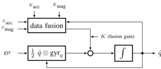
In addition to accelerometer and magnetometer, the gy-roscope is used to estimate variation of attitude. Unfortu-nately, the gyroscope bias leads after integration (Eq. (5)) to an angular drift, increasing linearly over time. Since the use of only gyroscope is not enough for attitude estimation, accelerometer and magnetometer are used to get an absolute quaternion and compensate the drift. The crux in solving an attitude estimation problem then consists in combining inertial and magnetic sensor measurements in a relevant manner. Fig. 2 illustrates the whole approach, where K is the fusion gain between data merged from accelerometer-magnetometer fusion and gyroscope integration. This gain is adjusted depending on sensors reliability.
III. RELATEDWORKS
Since 1965, a multitude of solutions have been proposed to resolve attitude estimation problem, such as TRIAD [16], QUaternion ESTimator (QUEST) [17], Singular Value de-composition method (SVD) [18], Kalman Filters (KF) [19], [20], [21], [22], [23], Extended Kalman Filters (EKF) [24], [25], [26], [27], [5], Unscented Kalman Filters (UKF) [28],
Sacc Smag gyr Eacc Emag data fusion 1 2 q ⊗ gyrˆ q K (fusion gain)
R
ˆ qFig. 2. Method for Attitude Estimation.
Adaptive Kalman Filters (AKF) [29], [30], Particle Filters [31] and more recently Observers [10], [32], [33], [34]. A survey and an analysis of these methods can be found in [35]. In 2007, Crassidis et al. provide another survey with a focus on nonlinear Attitude Estimation methods. In this paper we further focus on algorithms that use measurements from the 3 inertial sensors that are now commonly found on smartphones: gyroscopes, accelerometers and magnetometers, and attempt to leverage on these measurements to provide precise attitude estimation on smartphones carried by pedestrians.
Most algorithms developed so far rely on a common assumption: the external acceleration is negligible. However, when used in the context of smartphone carried by a pedes-trian, this assumption is questionable (we have experimentally observed high external accelerations: see e.g. first row of Ta-ble VI). Specifically, the relation betweenSacc andEacc given
by Eq. (6) is true only if no external acceleration is applied on the smartphone. Assumption of external acceleration is not a new problem, in [19], [20], [25], [22] authors propose to discard accelerometer values in the update phase of their KF. They set values of covariance matrix to infinity when:
kSacck − kEacck | {z } µ > γacc. (10)
In [27] and [36], they explain how they adjust the covariance matrix in function of the left term of Eq. (10). In [29] and [30], authors use KF residual errors to detect external acceleration. The technique proposed in [29] needs time to let residual matrix converge in a static phase to identify bias before estimating external accelerations. Finally, in [5], Renaudin et al. only perform the update phase of their KF during periods considered as Quasi Static Field (QSF). QSF is defined by a low variance of measurements. Eacc is replaced and adjusted during these phases. To the best of our knowledge, the use of a detector `a la (10) has not been investigated yet with an observer-based filter.
Most algorithms found in the literature do not consider magnetic perturbations. However, in the pedestrian context, the smartphone is often exposed to ferromagnetic objects, and this is known to yield bad attitude estimation [37], [38].
Few papers are concerned with magnetic perturbations for attitude estimation on a smartphone carried by a pedestrian. In [34], authors consider the impact of magnetic perturbations on the North-East plane, abstracting over other possible impacts. In [19] and [25], authors set the covariance matrix of magnetic measurements to infinity when:
kSmagk − kEmagk
In [19], in addition to detector (11), Harada et al. use the following property to detect magnetic perturbations:
θ(Sacc,Smag) − θ(Eacc,Emag) > γθ, (12)
where: θ(v1, v2) = arccos
v1· v2
kv1k · kv2k
.
Similarly to how external accelerations are treated, Renaudin et al. [5] use a QSF detector based on variance of measurements. An experimental benchmark comparing a subset of these filters was presented in [11].
In the present paper, we develop a new technique for limiting the impact of magnetic perturbations on attitude estimation algorithms that are executed on smartphones carried by pedestrians. In addition, we conduct extensive practical experiments focused on typical motions of smartphones carried by a pedestrian, and show how our approach compares and improves over previous works in this context. To the best of our knowledge, our systematic comparison of attitude estimation algorithms is the first in this context. Our experiments include 126 datasets with several typical motions, several devices, realistic magnetic perturbations, and a fine-grained analysis.
IV. EXISTINGALGORITHMSCONSIDERED We now review the state-of-the-art algorithms that we con-sider in our study. We have selected 8 filters from the literature. They have been selected because they are representative of the different techniques developed for solving the attitude estima-tion problem. We took care to consider the different approaches used for estimating attitude using the three inertial sensors. Our selection of algorithms can roughly be divided into two categories: those based on observers, and those based on KFs (with their EKF, UKF, and AKF variants). We summarize the main principles and objectives of each algorithm that we have implemented below (see [11] for a more formal description of each algorithm using a common notation). For reproducibility purposes, we also indicate parameters that we used with each tested algorithm – which we set in accordance with authors guidelines found in their papers. We also consider the “black-box algorithms” embedded in Android and iOS.
Mahony et al. [32]. This filter is a Complementary Filter designed for aerial vehicles. The main idea is to calculate the error by cross multiplying measured and estimated vectors. Mahony is the common implementation of the filter. MahonyB is the implementation which takes into account a bias. Parameters:β = 1, ζ = 0.2.
Madgwick et al. [34]. This filter is a Gradient Descent (GD) based algorithm designed for pedestrian navigation. Its authors propose to consider magnetic field deviations only on North-East plane using the following technique:
Emag = [0 m y mz] T , where my = q h2 x+ h2y,
mz = hz and h = ˆq−1 ⊗Smag ⊗ ˆq. Madgwick is the
common implementation of the filter, and MadgwickB the same with a bias. Parameters:β = 0.08, ζ = 0.016.
Fourati et al. [10]. This filter is a mix between a GD algo-rithm and the quadratic approach of Marquardt designed for bio-logging. Fourati is the common implementation of the filter. FouratiExtAcc is an extension which takes
external accelerations into account using Eq. (10)). Pa-rameters: β = 0.3, Ka = 2 and Km = 1. Ka = 0 when
γacc= 0.5m.s−2.
Martin et al. [33]. This filter is an observer with a new geo-metrical structure. Authors introduce new measurements based on the cross product of acc and mag. Martin is the common implementation of the filter. la = 0.7, lc =
0.1, ld= 0.01, n = 0.01, o = 0.01, k = 10, σ = 0.002.
Choukroun et al. [21]. This filter provides a linearization of measurement equations. A KF is applied and guarantees a global convergence. Choukroun is the common imple-mentation of the filter.
Renaudin et al. [5]. This filter is an EKF designed for PDR. In addition to Eq. (6) and Eq. (7), they use two others properties:
acct+1= qω−1⊗ acct⊗ qω, (13)
magt+1= qω−1⊗ magt⊗ qω, (14)
where qωis interpreted as a rotation between two
succes-sive epochs. Eq. (6), (7), (13) and (14) are applied only during Quasi-Static Field (QSF) periods. The detector for QSF works by analyzing variance of acceleration and magnetic field measurements on a small window (≈ 0.2s). This filter has to be initialized (≈ 5s at the beginning) without external accelerations and magnetic perturbations (mostly outside). Renaudin is the common implementation of the filter. In RenaudinBG, the gyro-scope bias estimation is added with gradients update from Eq. (13) and Eq. (14) are considered. RenaudinExtac-cExtmagtakes both QSF detectors into account. Parame-ters:QSF Window = 10, γQSF Acc= 3.92m.s−2, γQSF Mag =
6µT, outliersQSF Acc= 4.90m.s−2, outliersQSF Mag= 8µT .
Sabatini et al. [25]. This filter is an EKF which considers external acceleration and magnetic perturbations as ex-plained in §III. Sabatini is the common implementation of the filter. SabatiniExtacc and SabatiniExtmag takes respectively external accelerations and magnetic pertur-bations into account. We did not implement the bias part of this filter. Parameters: γacc = 0.5 m.s−2, γmag =
15 µT, γθ = 10°, mov averagemag= 0.1s
Ekf is the common implementation of the Extended KF. OS The Android API of Nexus 5 and iOS API of iPhones also
provides quaternions generated by undisclosed “black-box” algorithms. We include them in our comparisons. V. ANEW TECHNIQUE FOR LIMITING THE IMPACT OF
MAGNETIC PERTURBATIONS
The presence of magnetic perturbations in indoor environ-ments is well-known [38]. For example, Figure 3 illustrates variations of the magnetic field observed inside Inria’s research center compared to Earth’s magnetic field. To limit the impact of such magnetic perturbations, we now introduce a new approach that further builds on the idea of detectors `a la (11). The overall principle is twofold: (1) during periods when we detect magnetic perturbations, we can discard magnetometer measurements for a short period so that gyroscope measure-ments are given more importance; (2) this period should be reasonably short-enough so that the impact of gyroscope’s bias2 is limited.
2We experimentally measured the drift due to gyroscope’s bias integration
0 10 20 30 40 50 60 70 50 100 150 time [s] kmagk [µT ] measurement
Earth’s magnetic field
Fig. 3. Magnitude of magnetic field measurements and Earth’s magnetic field in the indoor environment of Inria building in Grenoble.
We propose an improvement of the magnetic perturbation detector (Eq. (11)) adapted to the pedestrian context. When a person is moving with a normal speed in a building, we have observed huge variations of magnitude of magnetic field
Smag
> 100 µT (see for example Fig. 3 at t = 24s). The main problem with the detector (11) is to find a proper γmag
which should be: (i) high enough not to discard magnetometer measurements due to low magnetic perturbations omnipresent in an indoor environment and (ii) small enough to reject high perturbations which affect attitude estimation (such as those coming from the proximity of e.g. heaters, see: §VI-C).
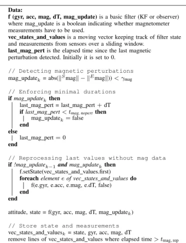
When the threshold of (Eq. (11)) is attained, generally the filter is already diverging. This means that when this detection occurs, and therefore when gyroscope integration starts, magnetometer measurements involving perturbations below the threshold have already impacted attitude estimation. Figure 4 presents our new technique to limit the impact of magnetic perturbations. The principle is that we reprocess the filter for the tmag, rep last seconds without magnetometer
measurements (Eq. (7)). When the detection occurs, attitude estimation is immediately replaced by these values. This technique avoids the attitude divergence during the tmag, replast
seconds before the detection (Eq. (11)). This technique can be used for real-time attitude estimation (time for reprocessing being negligible when compared to tmag, rep), in which case
a discontinuity of some degrees can be observed when the detection occurs (see Fig. 7).
During periods of magnetic perturbation, Eq. (11) can be true for a small duration. This is because magnitude of magnetometer measurement can be similar to Earth’s magnetic field magnitude during a perturbation phase, it depends on the direction of the perturbation. For this purpose a last condition is added: Eq. (7) can be used only if there is no detection (Eq. (11)) during the last tmag, nopert seconds.
This technique works with all filters where updates (Eq. (6)) from magnetometer can be temporarily removed (which is the case of all algorithms considered here). An im-portant prerequisite is magnetometer calibration. In a context without magnetic perturbations, magnitude of magnetometer measurements should be equal to the magnitude of Earth’s magnetic field.
In addition to the algorithms presented before, we also consider 2 new algorithms based on the aforementioned tech-nique. The first one, MichelObsF, is an implementation of the technique where f is the observer from Fourati et al. The second algorithm, MichelEkfF, is designed with f set to
Data:
f (gyr, acc, mag, dT, mag update) is a basic filter (KF or observer) where mag update is a boolean indicating whether magnetometer measurements have to be used.
vec states and values is a moving vector keeping track of filter state and measurements from sensors over a sliding window.
last mag pert is the elapsed time since the last magnetic perturbation detected. Initially it is set to 0.
// Detecting magnetic perturbations mag updatek= abs(kSmagk − kEmagk)) < γmag
// Enforcing minimal durations if mag updatekthen
last mag pert = last mag pert + dT if last mag pert < tmag, nopertthen
mag updatek= false end
else
last mag pert = 0 end
// Reprocessing last values without mag data if !mag updatek−1and mag updatek then
f.setState(vec states and values.first)
foreach element e of vec states and values do f(e.gyr, e.acc, e.mag, e.dT, false) end
end
attitude, state = f(gyr, acc, mag, dT, mag updatek)
// Store state and measurements vec states and valuesk= state, gyr, acc, mag, dT
remove lines of vec states and values where elapsed time > tmag, rep
Fig. 4. Pseudo-code for limiting the impact of magnetic perturbations.
the well known EKF filter from the literature. For both algo-rithms we use following common parameters: γmag = 15µT ,
tmag, nopert= 2s and tmag, rep= 3s.
VI. EXPERIMENTALPROTOCOL
We now explain our experimental methodology. A total of 126 trials have been conducted by 3 people with 3 different smartphones, following several typical motions in an environ-ment with low and high magnetic disturbances.
A. Ground Truth
Reference measurements have been made by a Qualisys system. This technology provides quaternions with a precision of 0.5° of rotation. Our room is equipped with 20 Oqus cameras connected to a server and a Qualisys Tracker software with a sampling rate at 150Hz. For the purpose of aligning timestamps of our ground truth data with the one of smart-phone’s sensors, we used a slerp interpolation [39]. The motion tracker reference frame has been aligned with EF using room orientation provided by architects.
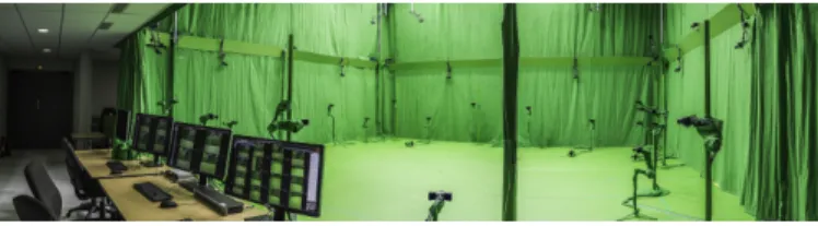
The room is a 10m × 10m square motion lab3 (see Fig. 5). In this room, we observed that the magnetic field is almost homogeneous from a sub-place to another (variations are less than 3µT ), and with negligible variations over time.
Fig. 5. Kinovis room at Inria, Grenoble, France.
A smartphone handler with infrared markers has been created with a 3D printer for this study and its markers have been aligned with SF (see Fig. 6).
B. Typical Smartphone Motions
We identify 8 typical smartphone motions, inspired from [40]: • Querying the context in augmented reality (see Fig. 6a). • Walking while user is texting a message (see Fig. 6b). • Walking while the user is phoning (see Fig. 6c). • Walking with a swinging hand (see Fig. 6d).
• Walking with the device in the front pocket (see Fig. 6e). • Walking with the device in the back pocket (see Fig. 6f). • Running with the device in the hand (see Fig. 6g). • Running with the device in the pocket (see Fig. 6h).
(a) AR (b) Texting (c) Phoning (d) Swinging
(e) Front Pocket (f) Back Pocket (g) Running Hand (h) Running Pocket Fig. 6. The eight typical motions for a smartphone.
AR motion is a slow motion typically found during AR experiences. Other motions happen when pedestrians move and are relevant for navigation applications. Each motion comes with particular external accelerations. The first row of Table VI shows the mean of external acceleration magnitude grouped by motion, for the 126 tests.
During tests, we observed that external accelerations almost never reach zero because the device is always moving, and constant speed is very unlikely when the device is held or carried in a pocket. However, we noticed a high variety of external accelerations: some motions involve external acceler-ations that are 20 times lower than gravity while others (like running hand) are closer to twice the value of gravity. We also noticed that the maximum swing of accelerometer (±2g) is often reached during our running experiments.
C. Introducing Magnetic Perturbations
During tests, we noticed that magnetic disturbances are always present in indoor-environments, and they vary between
different buildings. This is mainly due to building structure. We also observed in some cases, if user is close to heaters, electrical cabinets or simply close to a wall, magnitude of magnetic field can grow up to 150 µT during few seconds, that is 3 times more than Earth’s magnetic field (see e.g. Figure 3). The motion capture system used is located in a room with low and constant magnetic perturbations. In order to reproduce typical magnetic perturbations of indoor environments inside the motion lab, we used several magnetic boards. This allowed us to introduce magnetic perturbations similar to the ones described above. Specifically, during the 2 minutes tests, we brought the device to a few centimeters away from magnetic boards; and we repeated this action 3 or 4 times.
D. Different Devices
Measurements have been recorded with 3 different smart-phones from 2 manufacturers. The 3 smartsmart-phones used are a LG Nexus 5, an iPhone 5 and an iPhone 4S. We implemented a log application4 for Android and iOS. Table I summarizes
sensors specifications for the 3 devices.
TABLE I. SENSORS SPECIFICATIONS WITH THE MAX.SAMPLING RATE
Accelerometer Gyroscope Magnetometer iPhone 4S STMicro STM33DH STIMicro AGDI AKM 8975
100Hz 100Hz 40Hz
iPhone 5 STMicro LIS331DLH STIMicro L3G4200D AKM 8963
100Hz 100Hz 25Hz
Nexus 5 InvenSense MPU6515 InvenSense MPU6515 AKM 8963
200Hz 200Hz 60Hz
For the purpose of aligning timestamps of magnetic field and gyroscope data with data obtained from accelerometer, we used a linear extrapolation. In order to keep the focus on a real-time process, interpolation is not allowable here. We choose to align data at 100Hz. Moreover, for each trial, we chose to process 31 algorithms at 4 sampling rates and with 7 different calibrations, that is a total of more than 110 000 tests and 804 millions quaternions compared.
E. Common Basis of Comparison and Reproducibility To ensure a reasonably fast convergence of algorithms, we initialize the first quaternion using the first measurement of accelerometer and the first measurement of magnetometer. In addition, we discard the first five seconds from our results.
Most smartphone APIs (including Nexus 5 and iPhones) provide both calibrated and uncalibrated data from magne-tometer and gyroscope5, and only uncalibrated data from
accelerometer. Calibration phases can be triggered by the Android operating system at anytime. However, we notice that the gyroscope bias is removed during static phases and the magnetometer is calibrated during the drawing of an infinity symbol. For iOS devices, magnetometer calibration must be explicitly triggered by the user. The exact calibration algo-rithms embedded in both iOS and Android are not disclosed so we consider them as “black-boxes”.
To investigate the impact of calibration, we also developed a custom calibration procedure: every morning, we applied our own implementation of the calibration based on Bartz et
4https://github.com/tyrex-team/senslogs 5not from iOS API
al. [41] to remove soft and hard iron distortions from magne-tometer and based on Frosio et al. [42] for the accelerometer. In addition, for all calibrations we applied a scale to adjust magnitude to 9.8m.s−2for accelerometer and Earth’s magnetic field magnitude for magnetometer. For the gyroscope, we simply remove the bias by subtracting measured values in each axis during static phases.
The precision error is reported using the Mean Absolute Error (MAE) on the Quaternion Angle Difference (QAD) [43]. It allows to avoid the use of Euler angles with the gimbal-lock problem. The formula of QAD is defined by:
θ = cos−1(2hq1, q2i2− 1). (15) Since the accuracy of the system that provides the ground truth is ±0.5°, we consider that two algorithms exhibiting differences in precision lower than 0.5° rank similarly.
VII. RESULTS AND DISCUSSIONS
We made available the whole benchmark including the 110000+ of 2-minute results and the 126 datasets at: http: //tyrex.inria.fr/mobile/benchmarks-attitude. Tests can thus be reproduced. This benchmark makes it possible to evaluate new filters over a common ground truth, and to compute additional analytics like e.g. precision errors using Euler angles. In this Section we report on a few lessons learned, backed by aggregated views on a fraction of the obtained results.
A. Importance of Calibration
We tested attitude estimation algorithms in 6 different situations where magnetometer, gyroscope and accelerometer are either calibrated or not. Table II presents the results, that show that precision is impacted in the same way with all algorithms.
TABLE II. PRECISION OF ATTITUDE ESTIMATION ACCORDING TO CALIBRATION WITH ALL MOTIONS
Mag: No Gyr: No Acc: No Mag: Yes Gyr: No Acc: No Mag: Yes Gyr: No Acc: Yes Mag: Yes Gyr: Yes Acc: No Mag: Yes Gyr: Yes Acc: Yes Mag: OS Gyr: OS* Acc: No Choukroun 95.1° 16.5° 16.5° 9.9° 10.0° 17.3° Fourati 83.7° 15.6° 15.5° 10.3° 10.4° 16.3° Madgwick 77.5° 18.2° 18.2° 8.1° 8.1° 17.7° Renaudin 82.2° 19.5° 19.5° 8.0° 8.1° 18.1° Ekf 79.8° 19.4° 19.4° 7.9° 8.0° 18.2° MichelEkfF 82.0° 20.1° 20.1° 6.9° 7.0° 18.2° MichelObsF 82.1° 13.6° 13.5° 5.9° 5.9° 15.1°
* Not available for iOS devices
In a context free from magnetic perturbations, the magni-tude of uncalibrated magnetic field is about 350µT . This is why it is impossible to estimate attitude if calibration of hard iron distortions has not be done before. The gyroscope calibra-tion phase is mostly important during periods with no update from accelerometer and magnetometer values. If gyroscope is not calibrated, integration drift will grow from 5°.min−1 to 20°.min−1. We observe that accelerometer calibration does not significantly improve the precision of attitude estimation for the considered datasets. The way we performed calibration (see §VI-E) provides a significantly better precision in attitude estimation than the calibration performed by device-embedded algorithms.
B. The Difficulty with Noise for Kalman Filters
KFs are often used in the general domain of attitude estimation where white noises naturally model physical sensors noise. We know from theory that KF converge when the smartphone is static and magnetometer values correspond to Earth’s magnetic field. However, this is not the case in the context that we consider. The order of magnitude of external accelerations and magnetic perturbations experienced by the smartphone is much higher than its physical sensor noise.
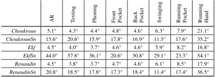
With values for sensors noise experimentally extracted (as commonly found in the literature), filters yield high precision errors and diverge quickly. This is shown in Table III where ChoukrounSn, RenaudinSn and EkfSn respectively denote the algorithms initialized with values for noise measured from physical sensors.
TABLE III. PRECISION OF ATTITUDE ESTIMATION ACCORDING TO SENSOR NOISES WITHOUT MAGNETIC PERTURBATIONS.
AR Texting Phoning Front Pock
et
Back Pock
et
Swinging Running Pock
et Running Hand Choukroun 5.1° 4.3° 4.4° 4.8° 4.6° 6.3° 7.9° 21.1° ChoukrounSn 15.6° 20.6° 15.9° 17.8° 16.9° 11.5° 17.6° 35.2° Ekf 4.5° 4.0° 3.7° 4.6° 4.6° 5.9° 8.2° 16.8° EkfSn 44.0° 57.8° 36.1° 20.6° 30.8° 29.1° 23.3° 54.1° Renaudin 4.5° 3.8° 3.7° 4.7° 4.6° 6.1° 8.5° 17.9° RenaudinSn 20.8° 18.5° 17.8° 17.3° 18.4° 11.4° 17.4° 36.5°
KFs can still give better results in this context, provided we adapt the “noise values” in a way that does not reflect anymore physical sensor noise, but that instead takes into account the relative importance of sensor measurements in this context. Gyroscope measurements are not impacted by external accelerations nor magnetic perturbations. In our con-text, we observed that giving more importance to gyroscope measurements (compared to magnetometer and accelerometer measurements) yields better results (despite convergence being a bit longer). Experimentally we obtained the best results (See Choukroun, Renaudin and Ekf in Table III) by using the following “noise values”: σacc= 0.5, σmag= 0.8, σgyr= 0.3
for all KFs6.
Applying KFs in this context remains non trivial, because the notion of noise to model in this context goes much beyond the setting in which initial KFs were designed.
Observers and KFs exhibit similar results for low to mod-erate external accelerations. For higher accelerations (typically found when swinging and running), observers were found to improve precision. This is especially the case for MichelObsF that outperforms MichelEkfF, as shown in Table V.
C. Bias Consideration
Many existing filters try to estimate sensors bias and in particular gyroscope bias. For example, in observers, typical procedures use residuals between reference and estimation to estimate bias (e.g. [32], [34]). In our setting however, residuals do not only originate from gyroscope bias but also from mag-netic perturbations and external accelerations. Furthermore, a calibration phase is performed in a previous stage.
6except for the Linear KF from Choukroun where we adapt these values
We can thus wonder how useful classical bias estimation techniques are in our setting. Table IV compares the results obtained with two variants of each filter: one with bias estimation and one without. We observe that bias estimation seems unnecessary in our context of study. We remark however that bias estimation can still be useful for situations where the gyroscope is not calibrated. In this particular case, precision of attitude estimation is improved with bias estimation, provided external accelerations remain small.
TABLE IV. PRECISION OF ATTITUDE ACCORDING TO BIAS ESTIMATION WITHOUT MAGNETIC PERTURBATIONS.
AR Texting Phoning Front Pock
et
Back Pock
et
Swinging Running Pock
et Running Hand Madgwick 4.8° 4.1° 4.6° 4.9° 5.0° 5.8° 7.1° 16.5° MadgwickB 5.2° 4.8° 5.4° 5.8° 6.2° 11.5° 10.5° 19.8° Mahony 5.0° 4.6° 4.2° 5.1° 5.2° 7.5° 7.9° 11.2° MahonyB 5.6° 4.9° 4.7° 6.1° 5.7° 9.9° 13.1° 26.4° Renaudin 4.5° 3.8° 3.7° 4.7° 4.6° 6.1° 8.5° 17.9° RenaudinBG 4.5° 3.7° 3.8° 4.5° 4.6° 6.9° 12.8° 19.3°
D. Behaviors during Typical Smartphone Motions
Table V compares the precision of attitude estimation for each motion. We observe a negative correlation between magnitude of external acceleration and precision of attitude estimation. This is verified for all algorithms.
TABLE V. PRECISION OFATTITUDE ESTIMATION ACCORDING TO TYPICAL MOTIONS WITHOUT MAGNETIC PERTURBATIONS.
AR Texting Phoning Front Pock
et
Back Pock
et
Swinging Running Pock
et Running Hand OS 7.1° 5.9° 5.8° 12.7° 13.2° 20.3° 24.4° 62.0° Choukroun 5.1° 4.3° 4.4° 4.8° 4.6° 6.3° 7.9° 21.1° Madgwick 4.8° 4.1° 4.6° 4.9° 5.0° 5.8° 7.1° 16.5° Mahony 5.0° 4.6° 4.2° 5.1° 5.2° 7.5° 7.9° 11.2° Fourati 4.8° 4.0° 4.4° 4.6° 4.8° 5.3° 6.3° 6.6° FouratiExtacc 4.9° 5.4° 4.7° 6.0° 5.7° 8.4° 12.2° 29.1° Sabatini 4.5° 4.0° 3.7° 4.6° 4.6° 5.9° 8.2° 16.8° SabatiniExtacc 4.5° 4.5° 4.0° 5.5° 5.0° 9.7° 15.0° 33.5° Renaudin 4.5° 3.8° 3.7° 4.7° 4.6° 6.1° 8.5° 17.9° RenaudinExtacc 4.5° 3.8° 3.7° 4.8° 4.8° 6.0° 8.0° 30.3° MichelObsF 4.8° 3.9° 4.4° 4.6° 4.8° 5.3° 6.3° 6.6° MichelEkfF 4.5° 4.0° 3.7° 4.6° 4.6° 6.0° 8.2° 16.8°
We observe that two algorithms stand out in terms of precision: Fourati and MichelObsF.
Table VI presents the left term µ of detector (Eq. (11)) and the magnitude of external accelerations (extracted from the ground truth). We observe that the two series are highly correlated (ρ > 99%). This suggests that it is possible to reasonably distinguish periods with high external accelerations. TABLE VI. COMPARING MAGNITUDE OF EXTERNAL ACCELERATION ANDµFROM(EQ. 10). RESULTS ARE MEANS OVER DATASETS GROUPED
BY MOTION INm.s−2
AR Texting Phoning Front Pock
et
Back Pock
et
Swinging Running Pock
et
Running Hand Ext. Acc. 0.58 1.09 1.11 2.49 2.54 5.28 9.57 16.39 µ 0.26 0.61 0.56 1.35 1.22 2.27 5.69 8.05
We also observe that filters which take external acceler-ations into account do not yield better precision than others. This can be explained by long periods of perturbations without the smartphone becoming completely static. Moreover, filters are very sensitive to false detections which make them quickly diverge. An interesting perspective for the further development of filters in this context would be to investigate how to better leverage the detection of periods with high external accelera-tions in order to improve precision of attitude estimation during those periods (Table V).
E. Impact of Magnetic Perturbations
We tested different motions in the presence/absence of magnetic perturbations (§VI-C). Results are shown in Ta-ble VII.
TABLE VII. PRECISION OF ATTITUDE ESTIMATION ACCORDING TO TYPICAL MOTIONS WITH MAGNETIC PERTURBATIONS.
AR Texting Phoning Front Pock
et Back Pock et Swinging OS 29.0° 24.4° 21.1° 19.8° 37.9° 19.2° Madgwick 18.2° 7.5° 7.8° 8.1° 9.4° 10.0° Mahony 31.8° 26.1° 30.0° 19.9° 13.9° 26.6° Renaudin 17.1° 7.0° 7.6° 8.9° 8.7° 9.5° RenaudinExtmag 16.8° 6.4° 7.3° 8.4° 8.4° 8.9° Sabatini 16.6° 7.0° 8.0° 8.9° 8.6° 10.1° SabatiniExtmag 14.6° 8.7° 8.9° 6.4° 8.4° 9.0° MichelObs 32.1° 14.0° 16.4° 14.6° 8.8° 19.1° MichelObsExtmag 18.0° 11.9° 11.4° 7.4° 8.8° 10.3° MichelObsExtmagWt 15.5° 9.2° 9.7° 7.1° 7.3° 10.1° MichelObsF 10.6° 5.4° 6.0° 5.8° 7.1° 7.7° MichelEkf 16.6° 7.0° 8.0° 8.9° 8.6° 10.1° MichelEkfExtmag 14.2° 8.9° 9.0° 5.5° 8.6° 9.2° MichelEkfExtmagWt 12.3° 6.3° 7.2° 5.3° 8.5° 8.7° MichelEkfF 10.8° 5.3° 5.5° 5.7° 10.3° 7.5°
We observe that filters which implement a magnetic pertur-bations detector dot not systematically exhibit a better behavior when compared to their native variant. However, if we extend them with our technique for enforcing minimal durations (See Fig. 4), precision is systematically improved when compared to their native variant.
RenaudinExtmagimplements a different detector for mag-netic perturbations based on variances which improves Re-naudin. However, RenaudinExtmag is very sensitive to false detections because Earth’s magnetic field is known only during the initial phase.
We observe that the two variants of our technique (MichelEkfF and MichelObsF) give better precisions for all motions except for the back pocket motion in the case of MichelEkfF. MichelObsF thus stands out: it provides a sig-nificantly better precision during periods of magnetic per-turbations even with high accelerations. We also notice that precision is improved regardless of the motion.
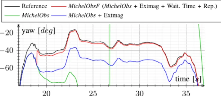
Figure 7 illustrates the relative improvements in precision brought by the respective components of our new technique presented in §V, in the case of yaw.
20 25 30 35 −60 −40 −20 time [s] yaw [deg]
Reference MichelObsF(MichelObs + Extmag + Wait. Time + Rep.) MichelObs MichelObs+ Extmag
Fig. 7. Sample run of the reprocessing technique (red) when a magnetic per-turbation occurs, in comparison to ground truth (black) and earlier techniques.
F. Comparison with Device-Embedded Algorithms
Table VIII shows algorithms precision depending on the smartphone used. For each algorithm, we observe rather similar results across the different smartphones. We also observe that TABLE VIII. PRECISION ACCORDING TO DEVICE WITH ALL MOTIONS
AND WITH/WITHOUT MAGNETIC PERTURBATIONS.
iPhone 4S iPhone 5 LG Nexus 5 OS 23.6° 28.6° 12.7° Choukroun 8.6° 10.4° 10.9° Mahony 10.8° 15.2° 16.6° Madgwick 7.1° 8.7° 8.6° Ekf 6.7° 8.7° 8.5° MichelObsF 5.4° 6.5° 5.9° MichelEkfF 5.6° 8.3° 7.0°
all algorithms exhibit a similar or better precision compared to OS-embedded algorithms. We know that this is at least partially due to a bad calibration (especially for iPhones). Finally, we notice that MichelEkfF and MichelObsF provide much better precision with all smartphones. Specifically, on 126 tests, we noticed that they improve the precision of OS-embedded algorithms on iPhone 4S by 300%, iPhone 5 by 250% and Nexus 5 by 100%.
G. Empirical Computational Complexity
Because of smartphone’s limited resources (e.g. battery), we study to which extent improvements in precision of attitude estimation have an impact in terms of empirical computational complexity. Figure 8 summarizes the relative times spent with each algorithm, where unit time corresponds to the running time of Mahony. Ratios have been obtained using the offline implementations executed across all 126 datasets.
Choukroun RenaudinExtaccExtmag MichelEkfF MichelObsF Ekf Fourati Madgwick Mahony 1 2.8 3.3 5.1 5.6 8.4 8.7 9
Fig. 8. Relative performance in terms of CPU cost (lower is better).
We observe that all algorithms can be executed on smart-phones even at much higher frequencies than current sensors
capabilities (see Table I). For example, our implementation of Mahony running on the Nexus 5 can output up to 45000 quaternions per second.
H. Relevant Sampling Rates
In all aforementioned results, sensors sampling rate was set to 100Hz. We studied the behavior of algorithms whenever the sampling rate varies. Table IX presents precision according to sampling rate. We observe that results with a sampling at 100Hz and 40Hz are relatively similar, and much more precise than with lower frequencies. This suggests to implement filters with a sampling rate of 40Hz to save smartphone’s battery life, for a negligible loss in precision.
TABLE IX. PRECISION ACCORDING TO SAMPLING WITH ALL MOTIONS AND WITH/WITHOUT MAGNETIC PERTURBATIONS.
100Hz 40Hz 10Hz 2Hz Choukroun 10.0° 10.1° 15.6° 34.7° Mahony 14.2° 14.3° 19.7° 48.9° Madgwick 8.1° 8.1° 17.3° 62.8° Ekf 8.0° 8.1° 15.3° 49.5° MichelObsF 5.9° 6.0° 14.8° 52.5° MichelEkfF 7.0° 7.1° 14.8° 51.3°
In our specific context, we obtain a mean error of 6° using our best algorithm (MichelObsF). When used in an AR appli-cation with geoloappli-cation and close tracked objects, this might be enough to avoid huge offsets during rendering. This might also be suitable for a navigation application with short trips. For longer trips, the additional use of a map-matching algorithm might be considered.
VIII. CONCLUSIONS
We investigate the use of attitude estimation algorithms in the particular context of pedestrians using commodity smart-phones. We propose a benchmark for evaluating and comparing the precision of attitude estimations during typical smartphone motions with and without magnetic perturbations. For the first time, our experiments shed light on the relative impacts of calibrations, noises, bias, motions, magnetic perturbations, and sampling rates when estimating attitude on smartphones. We also comment on lessons learned from our experiments for further research on the topic. In all cases, we recommend developers to use custom calibration and algorithms in replace-ment of those provided by smartphone’s OS. Our algorithm “MichelObsF” provides significant gains in precision when estimating attitude in the presence of magnetic perturbations. In the absence of magnetic perturbations, it offers the same precision than the most precise algorithms.
IX. ACKNOWLEDGMENTS
This work has been partially supported by PERSYVAL-Lab (ANR11-LABX-0025), EquipEx KINOVIS (ANR-11-EQPX-0024). We thank J.F. Cuniberto for the smartphone handler, J. Zietsch and G. Dupraz-Canard for having walked for hours to record data and M. Razafimahazo for providing the iOS app.
REFERENCES
[1] G. Wahba, “A least squares estimate of satellite attitude,” SIAM review, vol. 7, no. 3, pp. 409–409, 1965.
[2] W. GmbH, “Wikitude.” [Online]. Available: www.wikitude.com [3] Niantic, Inc., “Ingress.” [Online]. Available: www.ingress.com [4] ——, “Pokemon GO.” [Online]. Available: www.pokemongo.com [5] V. Renaudin and C. Combettes, “Magnetic, acceleration fields and
gyro-scope quaternion (MAGYQ)-based attitude estimation with smartphone sensors for indoor pedestrian navigation,” Sensors, vol. 14, no. 12, pp. 22 864–22 890, 2014.
[6] Google, “Street view for mobile.” [Online]. Available: https: //developers.google.com/streetview/android
[7] L. Ojeda and J. Borenstein, “Flexnav: Fuzzy logi c expert rule-based position estimation for mobile robots on rugged terrain,” in Robotics and Automation, 2002. Proceedings. ICRA’02. IEEE International Confer-ence on, vol. 1. IEEE, 2002, pp. 317–322.
[8] E. J. Lefferts, F. L. Markley, and M. D. Shuster, “Kalman filtering for spacecraft attitude estimation,” Journal of Guidance, Control, and Dynamics, vol. 5, no. 5, pp. 417–429, 1982.
[9] M. Euston, P. Coote, R. Mahony, J. Kim, and T. Hamel, “A comple-mentary filter for attitude estimation of a fixed-wing uav,” in Intelligent Robots and Systems, 2008. IROS 2008. IEEE/RSJ International Con-ference on. IEEE, 2008, pp. 340–345.
[10] H. Fourati, N. Manamanni, L. Afilal, and Y. Handrich, “A nonlinear filtering approach for the attitude and dynamic body acceleration esti-mation based on inertial and magnetic sensors: Bio-logging application,” Sensors Journal, IEEE, vol. 11, no. 1, pp. 233–244, 2011.
[11] T. Michel, P. Genev`es, N. Laya¨ıda, and H. Fourati, “A comparative anal-ysis of attitude estimation for pedestrian navigation with smartphones,” in Indoor Positioning and Indoor Navigation, 2015, p. 10.
[12] D. Sachs, “Sensor fusion on android devices: A revolution in motion processing,” [Video] https://www.youtube.com/watch?v= C7JQ7Rpwn2k, 2010, [Online; accessed 9-April-2015].
[13] J. B. Kuipers, Quaternions and rotation sequences, 1999, vol. 66. [14] J. Diebel, “Representing attitude: Euler angles, unit quaternions, and
rotation vectors,” Matrix, vol. 58, pp. 15–16, 2006.
[15] U. (NGA) and the U.K.’s Defence Geographic Centre (DGC), “The world magnetic model,” http://www.ngdc.noaa.gov/geomag/WMM, 2015, [Online; accessed 17-July-2015].
[16] H. D. Black, “A passive system for determining the attitude of a satellite,” AIAA journal, vol. 2, no. 7, pp. 1350–1351, 1964. [17] M. D. Shuster and S. Oh, “Three-axis attitude determination from vector
observations,” Journal of Guidance, Control, and Dynamics, vol. 4, no. 1, pp. 70–77, 1981.
[18] F. L. Markley, “Attitude determination using vector observations and the singular value decomposition,” The Journal of the Astronautical Sciences, vol. 36, no. 3, pp. 245–258, 1988.
[19] T. Harada, H. Uchino, T. Mori, and T. Sato, “Portable absolute orientation estimation device with wireless network under accelerated situation,” in International Conference on Robotics and Automation, vol. 2. IEEE, 2004, pp. 1412–1417.
[20] H. Rehbinder and X. Hu, “Drift-free attitude estimation for accelerated rigid bodies,” Automatica, vol. 40, no. 4, pp. 653–659, 2004. [21] D. Choukroun, I. Y. Bar-Itzhack, and Y. Oshman, “Novel quaternion
kalman filter,” Aerospace and Electronic Systems, IEEE Transactions on, vol. 42, no. 1, pp. 174–190, 2006.
[22] J. K. Lee, E. J. Park, and S. N. Robinovitch, “Estimation of attitude and external acceleration using inertial sensor measurement during various dynamic conditions,” IEEE transactions on instrumentation and measurement, vol. 61, no. 8, pp. 2262–2273, 2012.
[23] R. G. Valenti, I. Dryanovski, and J. Xiao, “A linear kalman filter for marg orientation estimation using the algebraic quaternion algorithm,” IEEE Transactions on Instrumentation and Measurement, vol. 65, no. 2, pp. 467–481, 2016.
[24] J. L. Marins, X. Yun, E. R. Bachmann, R. B. McGhee, and M. J. Zyda, “An extended kalman filter for quaternion-based orientation estimation using marg sensors,” in Intelligent Robots and Systems, 2001. Proceedings. 2001 IEEE/RSJ International Conference on, vol. 4. IEEE, 2001, pp. 2003–2011.
[25] A. Sabatini, “Quaternion-based extended kalman filter for determining orientation by inertial and magnetic sensing,” Biomedical Engineering, IEEE Transactions on, vol. 53, no. 7, pp. 1346–1356, 2006. [26] R. Zhu, D. Sun, Z. Zhou, and D. Wang, “A linear fusion algorithm for
attitude determination using low cost mems-based sensors,” Measure-ment, vol. 40, no. 3, pp. 322–328, 2007.
[27] R. Munguia and A. Grau, “Attitude and heading system based on ekf total state configuration,” in 2011 IEEE International Symposium on Industrial Electronics. IEEE, 2011, pp. 2147–2152.
[28] J. L. Crassidis and F. L. Markley, “Unscented filtering for spacecraft at-titude estimation,” Journal of guidance, control, and dynamics, vol. 26, no. 4, pp. 536–542, 2003.
[29] Y. S. Suh, “Orientation estimation using a quaternion-based indirect kalman filter with adaptive estimation of external acceleration,” IEEE Transactions on Instrumentation and Measurement, vol. 59, no. 12, pp. 3296–3305, 2010.
[30] A. Makni, H. Fourati, and A. Y. Kibangou, “Adaptive kalman filter for mems-imu based attitude estimation under external acceleration and parsimonious use of gyroscopes,” in Control Conference (ECC), 2014 European. IEEE, 2014, pp. 1379–1384.
[31] Y. Oshman and A. Carmi, “Attitude estimation from vector observations using a genetic-algorithm-embedded quaternion particle filter,” Journal of Guidance, Control, and Dynamics, vol. 29, no. 4, pp. 879–891, 2006. [32] R. Mahony, T. Hamel, and J.-M. Pflimlin, “Nonlinear complementary filters on the special orthogonal group,” Automatic Control, IEEE Transactions on, vol. 53, no. 5, pp. 1203–1218, 2008.
[33] P. Martin and E. Sala¨un, “Design and implementation of a low-cost observer-based attitude and heading reference system,” Control Engineering Practice, vol. 18, no. 7, pp. 712–722, 2010.
[34] S. O. Madgwick, A. J. Harrison, and R. Vaidyanathan, “Estimation of IMU and MARG orientation using a gradient descent algorithm,” in Rehabilitation Robotics (ICORR), 2011 IEEE International Conference on. IEEE, 2011, pp. 1–7.
[35] F. L. Markley and D. Mortari, “Quaternion attitude estimation using vector observations.” Journal of the Astronautical Sciences, vol. 48, no. 2, pp. 359–380, 2000.
[36] W. Li and J. Wang, “Effective adaptive kalman filter for mems-imu/magnetometers integrated attitude and heading reference systems,” Journal of Navigation, vol. 66, no. 01, pp. 99–113, 2013.
[37] M. H. Afzal, V. Renaudin, and G. Lachapelle, “Magnetic field based heading estimation for pedestrian navigation environments,” in Indoor Positioning and Indoor Navigation (IPIN), 2011 International Confer-ence on. IEEE, 2011, pp. 1–10.
[38] E. R. Bachmann, X. Yun, and C. W. Peterson, “An investigation of the effects of magnetic variations on inertial/magnetic orientation sensors,” in Robotics and Automation, 2004. Proceedings. ICRA’04. 2004 IEEE International Conference on, vol. 2. IEEE, 2004, pp. 1115–1122. [39] K. Shoemake, “Animating rotation with quaternion curves,” in ACM
SIGGRAPH computer graphics, vol. 19, no. 3. ACM, 1985, pp. 245– 254.
[40] V. Renaudin, M. Susi, and G. Lachapelle, “Step length estimation using handheld inertial sensors,” Sensors, vol. 12, no. 7, pp. 8507–8525, 2012. [41] P. Bartz, “Magnetic compass calibration,” Oct. 13 1987, US Patent
4,698,912.
[42] I. Frosio, F. Pedersini, and N. A. Borghese, “Autocalibration of MEMS accelerometers,” in Advanced Mechatronics and MEMS De-vices. Springer, 2013, pp. 53–88.
[43] D. Q. Huynh, “Metrics for 3D rotations: Comparison and analysis,” Journal of Mathematical Imaging and Vision, vol. 35, no. 2, pp. 155– 164, 2009.