DOE/ET-51013-292 A COMPARISON of RADIOACTIVE WASTE from FIRST GENERATION FUSION REACTORS
and FAST FISSION REACTORS with ACTINIDE RECYCLING*
M. Koch and M.S. Kazimi
April 1991
Plasma Fusion Center and
Department of Nuclear Engineering Massachusetts Institute of Technology
Cambridge, MA 02139 U.S.A.
*This work was partially supported by EG&G Idaho, Inc. and the U.S. Department of Energy under DOE Contract
No. DE-AC02-78ET-51013 and DE-FG02-91ER-54110
Reproduction, translation, publication, use and disposal in whole or in part, by or for the United States government
is permitted PFC/RR-91-9
A Comparison of Radioactive Waste
from First Generation Fusion Reactors
and Fast Fission Reactors with
Actinide Recycling
by
M. Koch and M.S Kazimi
Abstract
Limitations of the fission fuel resources will presumably mandate the replace-ment of thermal fission reactors by fast fission reactors that operate on a self-sufficient closed fuel cycle. This replacement might take place within the next one hundred years, so the direct competitors of fusion reactors will be fission reactors of the latter rather than the former type. Also, fast fission reactors, in contrast to thermal fission reactors, have the potential for transmuting long-lived actinides into short-long-lived fission products. The associated reduction of the long-term activation of radioactive waste due to actinides makes the comparison of radioactive waste from fast fission reactors to that from fusion reactors more rewarding than the comparison of radioactive waste from thermal fission reactors to that from fusion reactors.
Radioactive waste from an experimental and a commercial fast fission reactor and an experimental and a commercial fusion reactor has been characterized. The fast fission reactors chosen for this study were the Experimental Breeder Reactor
II.(EBR-I1) and the Integral Fast Reactor (IFR). The fusion reactors chosen for
this study were the International Thermonuclear Experimental Reactor (ITER) and a Reduced Activation Ferrite Helium Tokamak (RAFH2T).
The four reactors considered operate on an idealized self-sufficient closed fuel cycle, i.e. actinides and tritium are regarded as fuel and recycled back to the reactor. In the case of the two fast fission reactors, actinide recycling is possible without detrimental effects to the neutronics, because at the very high average neutron energies in these reactors, not only plutonium, but also most other actinides become fissionable, i.e. constitute fuel rather than poison. Realistically, the radioactive waste from the two fast fission reactors will contain
some actinides and that from the two fusion reactors will contain some tritium. However, since actual separation efficiencies are expected to be in the 99.9 % range, the radioactive waste will contain less than 0.1% of the actinides or the tritium. In contrast, thermal fission reactors do not operate on a self-sufficient dosed fuel cycle and hence their radioactive waste contains up to 100% of the actinides.
The fast fission and the fusion reactors have been approximated as a set of homogenized reactor components of simple cylindrical and/or hexagonal geom-etry. Reactor components as radioactive waste were characterized by several
parameters. These parameters describe the volume and activation of radioactive waste and are pertinent to US regulatory standards.
Build-up and decay of radionuclides in reactor components were simulated
by the computer codes ORIGEN-I for fast fission reactors and ONEDANT and REA C-IMfor fusion reactors. Auxiliary computer codes were developed to convert
the output of those three computer codes into radioactive waste parameters. The parameters were not normalized to the different power levels of the compared reactors, but rather evaluated for these reactors as built.
The comparison of radioactive waste parameters shows that radioactive waste from the experimental fast fission reactor may be less hazardous than that from the experimental fusion reactor. Inclusion of the actinides would reverse this conclusion only in the long-term. Radioactive waste from the commercial fusion reactor may always be less hazardous than that from the commercial fast fission reactor, irrespective of the inclusion or exclusion of the actinides. The fusion waste would even be far less hazardous, if advanced structural materials, like silicon carbide or vanadium alloy, were employed.
Also, radioactive waste from the experimental fast fission reactor may be less hazardous than that from the commercial fast fission reactor. This is a direct consequence of the utilization of highly 235U enriched fuel in EBR-IH resulting
in a lower activation than the utilization of uranium-plutonium-minor-actinides fuel in IFR. Radioactive waste from the commercial fusion reactor may be less hazardous than that from the experimental fusion reactor. This is a direct con-sequence of the utilization of standard materials (SS316) in ITER resulting in a higher activation than the utilization of Reduced Activation Materials (RAF) in
RAFHT. The generation of High Level Radioactive Waste (HLRW) is likely not
to be avoided even for RAPHT.
The volume of radioactive waste from the two fusion reactors is larger than the volume of radioactive waste from the two fast fission reactors. Material selection in the fusion reactors plays a far more important role in controlling the activation of the radioactive waste than it does in the fast fission reactors. If recycling of fusion reactor structural materials is found feasible in the future, the volume of radioactive waste from fusion reactors will be reduced.
Acknowledgements
This report is based on the thesis submitted by the first author to the MIT Department of Nuclear Engineering in partial fulfillment of the re-quirements for the degree of Master of Science in Nuclear Engineering.
Our gratitude is directed to Robert Hill from the Argonne National Lab-oratory and Yousry Gohar from the Argonne National LabLab-oratory, who kept us up to date on the Integral Fast Reactor and the International Thermonu-clear Experimental Reactor, respectively.
Bhavya Lal from the Massachusetts Institute of Technology and Fred Mann from the Hanford Engineering Development Laboratory were of valu-able help in the proper application of the ORIGEN-I and REA C-Il codes. Our special gratitude goes to John Massidda from Grumman Space Sys-tems, who provided literally invaluable help in all aspects of the application of computer codes. The same holds true for Robert Thayer and Mark
Lon-don from the MIT Plasma Fusion Center.
The comments provided by Stephen Herring and Steven Piet of EG&G Idaho, Inc. on a draft of this report are greatly appreciated.
Elizabeth Parmelee from the MIT Department of Nuclear Engineering and Janet Anderson from the MIT Plasma Fusion Center contributed great administrative support.
We gratefully acknowledge partial funding for this report provided by the Office of Magnetic Fusion Energy of the U.S. Department of Energy.
Contents
1 Introduction
1.1 Topic & Motivation . . . .
1.2 1.3 1.4 1.5 Background . . . . Focus . . . . Structure . . . . Previous Studies . . . .. . . 2 Radioactive Waste Parameters
2.1 Introduction ... 2.2 Volume ...
2.3 Radioactivity , . . . . 2.4 Whole Body y-Dose Rate . . 2.5 Decay power . . . . 2.6 Biological Hazard Potential
26 . . . . 26 . . . . 30 . . . . 31 . . . . 32 . . . . 35 . . . . 36 43I .7 Radioactive Waste C3lassircation . . . . 2.7.1 Low, Intermediate and High Level Radioactive Waste 2.7.2 Class A, Class B, Class C and Class D Radioactive W aste . . . . 2.8 Intruder Dose Rate . . . .. .. . .. . . . . . .. .. .. . . 2.8.1 Construetion Scenario . . . . 2.8.2 Agriculture Scenario . . . . 3 Methods of the Study 3.1 Introduction . . . . 3.2 Fast Fission Reactors . . . . 3.2.1 ORIGEN-II Neutron Activation Code . . . . 43 45 48 52 56 60 60 61 61 15 . . 15 - . 17 - - 19 . . 23 . . 24
3.3 Fusion Reactors . . . . 3.3.1 VMIBOB Code ...
3.3.2 ONEDANT Neutron Transportation Code 3.3.3 FLXWRT Code ...
3.3.4 AVEFLUX Code ... 3.3.5 COMCOMP Code ...
3.3.6 REAC-II Neutron Activation Code ....
3.4 OPOPOST & RECPOST Codes ... 3.5 Integration of the Codes ...
3.5.1 Fast Fission Reactors ...
3.5.2 Fusion Reactors ...
4 Description of the Reactors
4.1 Introduction . . . . 4.2 Fast Fission Reactors . . . . 4.2.1 The Experimental Breeder Reactor II . . . . 4.2.1.1 History & Objectives . . . . 4.2.1.2 Operation Schedule . . . . 4.2.1.3 Design . . . . 4.2.2 The Integral Fast Reactor . . . . 4.2.2.1 History & Objectives . . . . 4.2.2.2 Operation Schedule . . . . 4.2.2.3 Design . . . . 4.3 Fusion Reactors . . . . 4.3.1 The International Thermonuclear Experimental
Re-actor . . . . 4.3.1.1 History & Objectives . . . . 4.3.1.2 Operation Schedule . . . . 4.3.1.3 Design . . . . 4.3.2 The Reduced Activation Ferrite Helium Tokamak
4.3.2.1 History & Objectives . . . . 4.3.2.2 Operation Schedule . . . . 4.3.2.3 Design . . . . 4.4 Radioactive Waste Processing for Fast Fission Reactors .
81 81 82 83 83 86 88 92 92 93 93 94 97 97 98 100 .. 104 104 104 105 105 62 62 65 67 67 69 75 76 78 78 79
4.4.1 EBR-II and IFR Pyroprocesses . . . 105
4.4.2 Basic Chemistry . . . .. 108
4.4.3 EBR-II Pyroprocess . . . 110
4.4.3.1 Melt-refining Process . . . 110
4.4.3.2 Recovering Process . . . 112
4.4.3.2.1 Skull Oxidation Step . . . 112
4.4.3.2.2 Skull Reclamation Step . . . 113
4.4.4 IFR Pyroprocess . . . 113
4.4.4.1 Electro-refining Process . . . 113
4.4.4.1.1 Dissolution Step . . . 113
4.4.4.1.2 Separation Step . . . 115
4.4.4.2 Purifying Process . . . 116
4.4.4.3 Extracting and Stripping Process . . . 117
5 Comparison of the Reactors 120 5.1 Introduction . . . 120
5.1.1 Reactor Components as Radioactive Waste . . . 120
5.1.2 Cycle, Life-time & Decommissioning Radioactive Waste127 5.1.3 Presentation of the Comparison of Radioactive Waste 132 5.2 Volume . . . 133
5.3 Radioactivity . . . 135
5.4 Whole Body -y-Dose Rate . . . .. 144
5.5 Decay Power . . . 145
5.6 Biological Hazard Potential . . . 153
5.7 Radioactive Waste Classification . . . 153
5.8 Intruder Dose Rate . . . 162
5.8.1 Construction Scenario . . . 162
5.8.2 Agriculture Scenario . . . 165
5.9 Radionuclides in Radioactive Waste . . . 168
6 Summary and Conclusion 170 6.1 Summary . . . 170
6.2 Conclusion . . . 172
A Reactor Materials and Geometries 185
List of Figures
5.1 Comparison of Specific Radioactivity of Fission Products,
Activation Products and Actinides, EBRII and IFR . . ... . 124
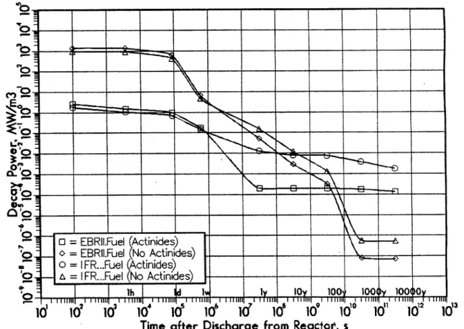
5.2 Comparison of Specific Decay Power of Fission Products, Ac-tivation Products and Actinides, EBRII and IFR ... .125
5.3 Comparison of Specific Biological Hazard Potential of Fission Products, Activation Products and Actinides, EBRII and IFR126 5.4 5.5 5.6 5.7 5.8 5.9 5.10 5.11 5.12 5.13 5.14 5.15 5.16 5.17 5.18 5.19 Specific Radioactivity EBR-II vs. ITER . . . 138
Specific Radioactivity IFR vs. RAFHT . . . 139
Life Time Absolute Radioactivity EBR-II vs. ITER ... .141
Life Time Absolute Radioactivity IFR vs. RAFHT . . . 142
Life Time Absolute -y-Dose Rate EBR-II vs. ITER ... .146
Life Time Absolute -y-Dose Rate IFR vs. RAFHT ... 147
Specific Decay Power EBR-II vs. ITER ... 148
Specific Decay Power IFR vs. RAFHT ... 149
Life Time Absolute Decay Power EBR-II vs. ITER ... .151
Life Time Absolute Decay Power IFR vs. RAFHT ... 152
Specific Biological Hazard Potential EBR-II vs. ITER . . .. 154
Specific Biological Hazard Potential IFR vs. RAFHT . . . . 155
Life Time Absolute Biological Hazard Potential EBR-II vs. ITER .. .... ... .. .. ... .. .. .. ... .. . 156
Life Time Absolute Biological Hazard Potential IFR vs. RAFHT157 Radioactive Waste Class C Index, EBR-II vs. ITER. . . . . 159
5.20 Intruder Dose Rate, Construction Scenario, EBR-II vs. ITER 163 5.21 Intruder Dose Rate, Construction Scenario, IFR vs. RAFHT 164 5.22 Intruder Dose Rate, Agriculture Scenario, EBR-II vs. ITER 166 5.23 Intruder Dose Rate, Agriculture Scenario, IFR vs. RAFHT . 167 B.1 Reactor Specific Radioactivity for EBR-II, IFR, ITER and
RAFHT ... 212 B.2 Reactor Life Time Absolute Radioactivity for EBR-I, IFR,
ITER and RAFHT . . . 213 B.3 Reactor Specific Decay Power for EBR-IJ, IFR, ITER and
RAFHT . . . .. . . . . 214 B.4 Reactor Life Time Absolute Decay Power for EBR-II, IFR,
List of Tables
2.1 Radiation Environments according to 10CFR20, Adapted from [47]... ... 37 2.2 Meaning and Dimension of PDC, Barrier and Auxiliary
Bar-rier Factors, Adapted from [8] . . . . 51 2.3 Barrier and Auxiliary Barrier Factors, Construction Scenario 53 2.4 Auxiliary Barrier Factors used in this Study, Construction
Scenario .. .. .. .. ... ... ... .... ... ... ... 55 2.5 Barrier and Auxiliary Barrier Factors, Agriculture Scenario 57 2.6 Auxiliary Barrier Factors used in this Study, Agriculture
Sce-nario . . . . 59 4.1 Volumes and Masses of Experimental Breeder Reactor II
Clad, Duct and Fuel Components, Adapted from [44,53,54]. 91 4.2 Volumes and Masses of Experimental Breeder Reactor II
Shield Component, Adapted from [44,53,54] . . . . 92 4.3 Volumes and Masses of Integral Fast Reactor Clad, Duct and
Fuel Components, Adapted from [14,17,25,34,35,51] . . . . . 95 4.4 Volumes and Masses of Integral Fast Reactor Reflector and
Shield Components, Adapted from [14,17,25,34,35,51]. . . . 96 4.5 Stages of ITER Physics Phase, Adapted from [21,22] . . . . 98 4.6 Substages of Stage 3 of ITER Physics Phase, Adapted from
[21,22] . . . . 99 4.7 Average Neutron First Wall Load of ITER Operation Phases 100
4.8 Volumes and Masses of International Thermonuclear Exper-imental Reactor Components, Adapted from [11,21] . . . 102 4.9 Weight Densities and Solid Volume Fractions of International
Thermonuclear Experimental Reactor Components, Adapted from [11,21] . . . 103 4.10 Volumes and Masses, Weight Densities and Solid Volume
Fractions of Reduced Activation Ferrite Helium Tokamak Components, Adapted from [19] . . . 106
4.11 Oxidation and Reduction Potentials, Adapted from [3,5]. . . 108
4.12 Free Energy of Formation at 500'C, Adapted from [5] . . . . 111
5.1 Summary of Operation Schedules . . . 129 5.2 Definition of Cycle, Life-time and Decommissioning
Radioac-tive W aste . . . .. ... . . . . 131 5.3 Volumes of Cycle, Life Time and Decommissioning
Radioac-tive W aste . . . 134 A.1 Element Composition of Assembly of Experimental Breeder
Reactor II Clad Component . . . 186 A.2 Element Composition of Assembly of Experimental Breeder
Reactor II Duct Component . . . 186 A.3 Isotope and Element Composition of Assembly of
Experi-mental Breeder Reactor II Fuel Component, Adapted from
[44] ...
187
A.4 Element Composition of 100% of Experimental Breeder Re-actor II Shield Component . . . . ... . . . 188 A.5 Element Composition of 100% of Integral Fast Reactor Clad
Component . . . 188 A.6 Element Composition of 100% of Integral Fast Reactor Duct
A.7 Isotope and Element Composition of 25% of Integral Fast Reactor Fuel Component, Adapted from [51] . . . 190 A.8 Element Composition of 100% of Integral Fast Reactor
Re-flector and Shield Components . . . 191 A.9 Material Composition of International Thermonuclear
Ex-perimental Reactor Components, Adapted from [11,21,22] . 192 A.10 Radial Build of International Thermonuclear Experimental
Reactor Inboard Components, Adapted from [11,21]. . . . . 193 A.11 Radial Build of International Thermonuclear Experimental
Reactor Inboard Components, Continued, Adapted from [11,21]194 A.12 Radial Build of International Thermonuclear Experimental
Reactor Outboard Components, Adapted from [11,21]. . . . 195 A.13 Radial Build of International Thermonuclear Experimental
Reactor Outboard Components, Continued, Adapted from [11,21] . . . 196 A.14 Material Composition of Reduced Activation Ferrite Helium
Tokamak Components, Adapted from [19] . . . 197 A.15 Radial Build of Reduced Activation Ferrite Helium Tokamak
Inboard Components, Adapted from [19] .. . . .. 197 A.16 Radial Build of Reduced Activation Ferrite Helium Tokamak
Outboard Components, Adapted from [19] . . . 198 A.17 Element Composition of Structure Material, Adapted from
[12,17,19]... ... .. . . . .. 199 A.18 Element Composition of Conductor and Breeder Material,
Adapted from [19] . . . 200
B.1 Specific Radioactive Waste Parameters at 10years after Dis-charge . . . 202 B.2 Specific Radioactive Waste Parameters at 100years after
B.3 Specific Radioactive Waste Parameters at 1000years after Discharge . . . 204 B.4 Absolute Radioactive Waste Parameters for Cycle
Radioac-tive Waste at 10years after Discharge . . . 205 B.5 Absolute Radioactive Waste Parameters for Life Time
Ra-dioactive Waste at 10years after Discharge . . . 206 B.6 Absolute Radioactive Waste Parameters for Decommission
Radioactive Waste at 10years after Discharge . . . 207 B.7 Absolute Radioactive Waste Parameters for Cycle
Radioac-tive Waste at 100years after Discharge . . . 208 B.8 Absolute Radioactive Waste Parameters for Life Time
Ra-dioactive Waste at 100years after Discharge . . . 209 B.9 Absolute Radioactive Waste Parameters for Cycle
Radioac-tive Waste at 1000years after Discharge . . . 210 B.10 Absolute Radioactive Waste Parameters for Life Time
Chapter 1
Introduction
1.1
Topic & Motivation
The energy supply structure of a society must be based on diverse energy conversion systems in order to guarantee the efficiency, flexibility and reli-ability of this structure. A typical such structure may consist of coal, oil, gas, nuclear and solar energy conversion systems. These different systems have different impacts on the environment.
One of the most important problems with respect to the environmen-tal impact of nuclear energy conversion systems consists of the radioactive waste that is inevitably generated by them. The principal techniques to handle radioactive waste and store it for the short-term and the intermediate-term are known. Such waste management is accomplished at many facilities in the United States (Hanford, Savannah River), Great Britain (Sellafield), the Federal Republic of Germany (Karlsruhe, Asse, Gorleben), Sweden
(Forsmark) and France (LaHague) [4].
However, considerable uncertainties exist with respect to the best ap-proach to be used for long-term storage of radioactive waste. Those uncer-tainties are reflected in the economical and political indecision on nuclear energy in general and hence create a virtual deadlock in the process of finding a solution to this problem. Thus it is important in this context to
minimize the need for long-term radioactive waste storage.
It must be noted that the radioactive waste produced by nuclear fission
and nuclear fusion - the two forms of nuclear energy - is generally
dif-ferent, especially in the long-term. Furthermore, it is well recognized that radioactive waste from thermal and fast fission reactors with once-through fuel cycle is more hazardous than that from fusion reactors, basically be-cause of the high content of long lived-actinides.
However, advanced fast fission reactors offer the opportunity of separat-ing the actinides from the radioactive waste and recyclseparat-ing them back to the reactor [5,44]. The comparison conducted in this study determines the fea-tures of radioactive waste from such advanced fast fission reactors and from fusion reactors. The study might thus provide evidence that radioactive waste from advanced fast fission reactors is not inherently more hazardous than that from fusion reactors.
Unlike actinide separation and recycling, separating long-lived nuclides from the radioactive waste of fusion reactors and recycling them back to the reactor has not been demonstrated yet and therefore will not be considered for this study. Nevertheless, theoretical concepts for such kind of separation and recycling do exist [50].
This comparative study of waste is important in view of the upcoming need for clean but efficient energy conversion systems to satisfy the world's ever growing demand for energy. However, following the diversity principle, this study does not suggest an "either-or" decision between advanced fast fission energy and fusion energy.
Fast fission and fusion energy are represented in this study by corre-sponding nuclear reactors and the radioactive waste produced by them is compared directly. The comparison shall be done for reactors of the experi-mental and the commercial type, because the radioactive waste produced by these different types of reactors is expected to be different. The comparison will be provided in terms of radioactive waste parameters which characterize
the volume and the specific and absolute activation of the waste.
1.2
Background
The absorption of neutrons by a given nuclide either leads to its fission or its transmutation. The proper joining of nuclides leads to their fusion. All three cases give rise to new radioactive or non-radioactive nuclides. Those nuclides represent isotopes of almost all the elements of the periodic table. The following list gives an overview over the most important elements in this context. The list is arranged according to the common chemical classification of elements [3,5].
1. Alkali Metals: Li, Na, K, Rb, Cs, Fr.
2. Alkaline Earth Metals: Be, Mg, Ca, Sr, Ba, Ra.
3. Lanthanides: La, Ce, Pr, Nd, Pm, Sm, Eu, Gd, Tb, Dy, Ho, Er, Tm, Yb, Lu; also referred to as Rare Earth Metals.
4. Actinides: Ac, Th, Pa, U, Np, Pu, Am, Cm, Bk, Cf; also referred to as Transuranics, if three elements, Ac, Th and Pa, which rank before uranium, and uranium itself are excluded. The transuranics without Pu are referred to as Minor Actinides.
5. General Metals: Cr, Mn, Fe, Co, Ni, Cu, Y, Zr, Nb, Mo, Tc, Ru, Cd, In, Sn, Sb, Te, Pb, Bi, and others.
6. Noble Metals: Rh, Pd, Ag, Ir, Pt, Au, Hg, and others. 7. Noble Gases: He, Ne, Ar, Kr, Xe, Rn.
It is useful to arrange the elements and their isotopes in groups, since the difference between the radioactive waste from fission and fusion reac-tors is characterized by its composition of those groups. Four groups are
generally distinguished; actinides, fission products, fusion products and ac-tivation products. Fission products are generated by fission, fusion products by fusion and actinides and activation products by transmutation. Fission products, actinides and the minor part of activation products originate in fission reactor fuel and fusion products originate in fusion reactor
fuel.
The major part of activation products originates in fission and fusion reactorstructure and coolant.
An important subset of actinides are non-easily fissile isotopes of ac-tinides that are converted to easily fissile isotopes of acac-tinides by transmu-tation. Those isotopes of actinides are called fertile isotopes.
Neutrons are necessary to maintain the immediate fission reaction in fis-sion fuel. Hence, the generation of fisfis-sion products, actinides and activation products is inherent to fission reactors. This holds true for all fission fuels. No neutrons are necessary to maintain the immediate fusion reaction in fu-sion fuel. Hence, only the generation of fufu-sion products is inherent to fufu-sion reactors. Depending on the fusion fuel, the fusion reaction may generate neutrons. The easiest to achieve, and therefore intensively pursued, fusion reaction is the one between Deuterium and Tritium (D-T reaction). It will generate neutrons and hence activation products are inherent to these fu-sion reactors, too. For both fisfu-sion and near-term D- T fufu-sion reactors to breed their own fuel, neutrons are mandatory.
Fusion products consist entirely of hydrogen or helium, while fission products generally comprise alkali metals, alkaline earth metals, rare earth metals, general metals, noble metals and noble gases. Activation products contain an elemental range comparable to the one of fission products. How-ever, isotopes of elements of fission products have a far higher number of neutrons than isotopes of the same elements of activation products. There-fore, fission products usually feature a far higher specific activation than activation products. While fission and fusion products are more or less the same for any fission or fusion fuel, activation products and the
associ-ated specific activation can differ considerably with different structure and coolant used in fission and fusion reactors.
The neutron flux is within approximately one order of magnitude in almost all components of a fission reactor, but can differ by several or-ders of magnitude in components of a fusion reactor. The peak neutron flux in fission and fusion reactors, however, is approximately the same
(1013 ... 1jO5;;"), although with a different energy spectrum (0.025eV... 10MeV for thermal and fast fission reactors, 0.025eV ... 14MeV for D-T fusion reactors).
Thus on the one hand, fission reactors produce radioactive waste with a far higher specific activation than fusion reactors do. But on the other hand, fusion reactors generate a much larger volume of radioactive waste than fission reactors do, which possibly could result in a far higher absolute activation for fusion reactors than for fission reactors.
1.3
Focus
The characteristic feature of a self-sufficient fuel cycle is the breeding of fuel atoms by irradiation of fertile atoms with neutrons. The breeding takes place in parallel to the power generation in a reactor. Breeding and power generation are conflicting goals, because efficient breeding requires short irradiation times, while efficient power generation requires long irra-diation times. Short irrairra-diation times allow fuel atoms to build up without being destroyed again by subsequent fission or transmutation. Long irradi-ation times allow to extract as much energy as possible from the fuel atoms without expensive refueling of the reactor [27].
The breeding performance of a reactor is measured in terms of its breed-ing ratio. It is defined as the ratio of the number of generated fuel atoms to the number of consumed fuel atoms. Apparently, in a given reactor, fuel atoms that release only few neutrons per fission or fusion reaction
-provided the latter one generates neutrons at all - will result in a lower breeding ratio than fuel atoms that release more neutrons per respective reaction. Thus the neutron yield of the fission or corresponding fusion re-action is a decisive factor in determining the breeding ratio [27].
A breeding ratio of greater than unity means a net generation of fuel atoms, a breeding ratio of less than unity means a net consumption of fuel atoms. Note, that a breeding ratio of greater than unity does not bring about a perpetuum mobile, because now fertile atoms have to be replenished instead of fuel atoms. Fertile atoms have a greater natural abundance than fuel atoms and hence breeding only means that the resources of fuel atoms can be extended by utilizing the resources of fertile atoms. In particular, this results in a longer life-time of an energy conversion system based on fission or (D-T) fusion.
Since the tritium component of D-T fusion fuel is not naturally abun-dant, D- T fusion reactors operate on a self-sufficient fuel cycle by necessity. The lithium isotopes 'Li and 'Li serve as the fertile isotopes and the hy-drogen isotope T = 3H - together with the naturally abundant hydrogen isotope D = 'H - serves as the fuel isotope. Fission fuel is naturally abun-dant, so that an immediate necessity for a self-sufficient fuel cycle does not exist. However, the natural resources of uranium, which is the major fis-sion fuel, are relatively limited. This can be concluded from some basic considerations.
At the current rate and the current method of uranium usage in thermal fission Light Water Reactors (LWR), this major fission fuel will be depleted within approximately one hundred years. An average 1, OOOMW. = 1GW' LWR requires annual refueling equivalent to 25t of enriched uranium. With-natural uranium having 0.72nuclide - % 23 U and enriched uranium having 3.3nuclide - % 2 sU, the amount of natural uranium necessary to manufac-ture 25, of enriched uranium is about 150 Gy, i.e six times as high.
Reference [33] quotes natural uranium resources recoverable at a price of less than 130- to be approximately 6 million tons. The current LWR reactor population makes for 400GW, resulting in an annual natural ura-nium demand of 60, 000t. That does not account for a possible increase in the reactor population, e.g. due to coal, oil and gas energy being replaced by fission energy. Hence, the natural uranium resources will last for not more than another one hundred years. The same reference cites a number of 4 billion tons of natural uranium dissolved in seawater. This could secure the supply of natural uranium for another seventy thousand years, however at a price of more than 500 ... 1, 000$. Moreover, possibly only 10% of thekg~
natural uranium dissolved in seawater could be recovered, i.e. the seventy thousand year supply shrinks to seven thousand years [33].
Also, approximately 350, 000t or 350, 000m3 seawater have to be pro-cessed to gain only 1kg of natural uranium. With the above natural uranium demand of 60, 000 , an amount of seawater equal to 2.1.1013 or 665, 000 3 would have to be processed - a formidable task for ion exchangers [33].
Thus, a self-sufficient fuel cycle seems to be mandatory for fission energy to continue being a major energy source beyond the point in time where fusion energy could become available. Moreover, fission reactors operating on a self-sufficient fuel cycle shall be chosen for the outlined comparison to enhance comparability of fission and fusion reactors as well as that of reactor concepts.
It is possible to operate thermal fission reactors on a self-sufficient fuel cycle. Then, the thorium isotope 232Th serves as the fertile isotope and the uranium isotope 2 33U serves as the fuel isotope. However, 23.U has a low neutron yield in the thermal energy range, so that the breeding ratio is only slightly greater than 1.0. It is easier to operate fast fission reactors on a self-sufficient fuel cycle, where advantage can be taken of the high neutron yield of the plutonium isotope 239Pu in the fast energy range. Then, the
uranium isotope 23 8U serves as the fertile isotope and 23 9Pu serves as the
fuel isotope. The breeding ratio of fast fission reactors can be as high as 1.3. Therfore, only fast fission reactors offer a sufficient potential for breeding. In any case, if no 233U or 239Pu is initially available, the reactor start-up
would have to be done by using 23 5U [27,56].
As mentioned in Section 1.1, a solution to the problem of long-term stor-age of radioactive waste does not yet exist. Hence, any measure that lowers the long-term hazard of radioactive waste without drawing upon a specific
long-term storage method could be suitable to alleviate this problem. In particular, it is appropriate to separate actinides from the remainder of the radioactive waste from fast fission reactors, especially since a major share of these represents potential fuel in addition to the bred 2 3 9Pu. This is due to the fact that most actinides become economically fissionable at high neutron energies and do no longer represent a reactor poison then. Also, without such a separation, the intended comparison would be dis-torted, because there is no comparably long-lived counterpart to actinides in radioactive waste from fusion reactors.
It must be noted however, that actinide separation will not be complete, since the chemical processes involved do not allow for a 100%, but rather only 99.9% separation efficiency [2]. The radioactive waste from fast fission reactors will thus always retain some actinides. However, the simplifying assumption of complete separation is made for the purpose of this study. The effect of this assumption on the radioactive waste parameters and its justification is assessed in Section 5.1.1.
Finally, recent developments in fission as well as fusion reactor technol-ogy and design lend themselves to a comparison of the outlined type.
The Integral Fast Reactor (IFR) concept was launched in 1984 by the
Argonne National Laboratory (ANL) [5]. It represents a self-sufficient
com-mercial fast fission reactor.
oper-ation of the Experimental Breeder Reactor I (EBR-1) and the self-sufficient Experimental Breeder Reactor II (EBR-I1) back in the 1950s and 1960s [44]. EBR-II was to be the final step before a commercial fast fission reactor.
The Reduced Activation Ferrite Helium Tokamak (RAFHT) is a self-sufficient commercial fusion reactor proposed in 1989 by the Senior Com-mittee on Environmental, Safety and Economy Aspects of Magnetic Fusion Energy (ESECOM) [19]. It has the highest potential for realization among other commercial fusion reactors considered by ESECOM.
The International Thermonuclear Experimental Reactor (ITER) is being developed since 1988 under the auspices of the International Atomic Energy Agency (IAEA) [23]. It represents an experimental fusion reactor that is to be the final step before a commercial fusion reactor.
The experimental nuclear reactors EBR-II and ITER have similar demon-strative functions with respect to the commercial nuclear reactors JFR and
RAFHT. EBR-II was designed to establish operation experience with and confirm the feasibility of a self-sufficient fuel cycle for a fast fission reactor. ITER roughly has the same goals for a fusion reactor. However, EBR-II could start out with a functioning fast fission reaction, while ITER first has
to show that the fusion reaction can be maintained at all.
1.4
Structure
This study will cover only a small section of the wide field of radioactive waste. Precise definitions and limitations within this small section have to be established.
Chapter 2 provides a detailed definition of what is to be considered radioactive waste in this study and presents the definitions of and possible standards for the radioactive waste parameters to which the comparison is oriented.
Chapter 3 gives an overview of the methods applied to obtain the dif-ferent radioactive waste parameters for the difdif-ferent nuclear reactors. This
comes basically down to a description of the different computer codes em-ployed to calculate the radioactive waste parameters.
Chapter 4 describes in detail the two fast fission and two fusion reactors considered in this study. The histories and objectives, the operation sched-ules and the designs are covered for all nuclear reactors. For fast fission reactors, additional information is given on the reprocessing of radioac-tive waste, especially on the separation of actinides from radioacradioac-tive waste. Knowledge about those aspects is important to the correct interpretation of the comparison. For fusion reactors, information on the reprocessing of radioactive waste is not given, because as of now no appreciable reprocess-ing concepts exists. Notwithstandreprocess-ing this fact, exemplary ideas of fusion reactor radioactive waste reprocessing are given in Reference [50].
Chapter 5 presents the actual comparison, showing the radioactive waste parameters for experimental and commercial nuclear reactors and giving explanations for particular behavior modes of those parameters.
Chapter 6 completes this study with a summary and conclusion. Ap-pendix A contains various tables with detailed information necessary to understand the essence of this study. Appendix B carries tables and fig-ures that were too numerous or extensive to be given in Chapter 5. The computer codes developed by the author of this study and all information necessary to run them are filed with the computer librarian of the Depart-ment of Nuclear Engineering of the Massachusetts Institute of Technology. Therefore, a listing of the computer codes shall be forgone here.
1.5
Previous Studies
Several studies have been conducted with respect to radioactive waste from fast fission and fusion reactors. The set of radioactive waste parameters chosen for those studies generally is more sparse and often different from the one chosen for this study. The same holds true for the times after discharge
from the nuclear reactor at which the radioactive waste is characterized by those radioactive waste parameters.
Even if comparable radioactive waste parameters or times were cho-sen, the type of characterization of radioactive waste still is different, i.e. radioactive waste parameters are sometimes applied only to nuclides con-tained in radioactive waste and sometimes only to radioactive waste as an entity. Also, specific radioactive waste parameters are related to different magnitudes, like mass or volume of radioactive waste or electric power out-put of the nuclear reactor. Only a few of those studies compare radioactive waste from fast fission and fusion reactors directly to each other. All this leads to a lack in consistency. The studies conducted so far shall be briefly listed here.
"The EBR-II Fuel Cycle Story" [44] covers the EBR-II self-sufficient closed fuel cycle and the radioactive waste associated with it. The study "Fusion Waste Management - Safety and Environment Studies 1985-1986
-" [12] describes radioactive waste produced by the Next European Torus
fusion reactor (NET). It is the most detailed study on fusion reactor ra-dioactive waste and the results are supposed to be applicable to ITER also. The report "Safety and Environment for ITER, Records and Conclu-sions" [10] is a misnomer for a study that considers radioactive waste from fusion reactors similar to ITER but not from ITER itself. The study "US-Contributions to the Homework for ITER" [11] covers radioactive waste from ITER in some detail. The "Report of the Senior Committee on Envi-ronmental, Safety and Economic Aspects of Magnetic Fusion Energy" [19] compares commercial fusion reactors and a commercial fast fission reactor and also contains some sections about associated radioactive waste. The book "Fusion and Fast Breeder Reactors" [13] extensively deals with the entire self-sufficient fuel cycle of fast fission and fusion reactors and with radioactive waste associated with it. However, it does not provide a direct comparison of radioactive waste from fast fission and fusion reactors.
Chapter 2
Radioactive Waste Parameters
2.1
Introduction
a-, 0- and y-radiation emitted by radioactive nuclides, i.e. radionuclides, during their radioactive decay interact with cells of all life forms of the biosphere. This interaction can have negative or positive effects on a cell. Because of either outcome of the interaction, the exposure of the biosphere to radiation from radionuclides represents a hazard to the biosphere.
The hazard depends on the type and concentration of radionuclides in the biosphere. Natural radionuclides are in equilibrium with the biosphere and the biosphere therefore is adapted to them. For man-made radionu-clides, as produced in the application of fast fission or fusion reactions, the type and concentration upset the equilibrium of the biosphere and the biosphere therefore is not adapted to them.
Equilibrium will be reached for man-made radionuclides only after their radioactive decay has occured. During the time required for this radioac-tive decay, radiation from man-made radionuclides should be isolated from the biosphere in order to keep the associated hazard low. Isolation en-compassing radiation from man-made radionuclides implies isolation of the radionuclides themselves.
Radioactive waste contains radioactive and non-radioactive nuclides. Since separation of radioactive from non-radioactive nuclides is
economi-cally and technieconomi-cally hardly feasible, all the radioactive waste has to be isolated from the biosphere, rather than just the radioactive nuclides.
Radioactive waste management can be defined as comprising the two tasks of radioactive waste handling and radioactive waste storage. Ra-dioactive waste handling shall be understood as the sum of all activities that transport radioactive waste and convert it into, or retrieve it from, a waste form contained in a waste container. Waste form and waste con-tainer compose a waste package suitable for radioactive waste storage. The conversion might either happen directly or with previous, the retrieval di-rectly or with subsequent reprocessing of the radioactive waste. Radioactive waste storage shall be understood as the sum of all activities that transport and store waste packages. Storage may be done temporarily (Monitored Retrievable Storage) and/or finally, depending on whether the radioactive waste requires temporary storage to establish by radioactive decay of its radionuclides conditions suitable for final storage. Between temporary and final radioactive waste storage, radioactive waste handling could be neces-sary.
Structural stability of a waste package is a basic prerequisite for the isolation thus devised to be effective. As a function of time, a stable waste package will deteriorate to an unstable waste package. This, however is supposed to happen in times on the order of those necessary for radionu-clides to reach equilibrium. Backfilling of void spaces in waste packages and in between waste packages with grouting or equivalent material can delay
(but also promote) the deterioration and increases the isolation.
Isolation of radioactive waste must be ensured both during radioactive waste handling and storage. Isolating radioactive waste rather than dis-carding it renders the term radioactive waste storage more appropriate than the term radioactive waste disposal and consequently the term repository is used for the corresponding radioactive waste storage facility, rather than the term dump for a radioactive waste disposal facility.
Depending on the type and concentration of radionuclides in radioactive waste, it will be classified as low, intermediate or high level radioactive waste and the task of isolation of radioactive waste assumes different degrees of difficulty with this classification. High level radioactive waste has to be stored in deep repositories according to Part 60 of Chapter 10 of the Code of Federal Regulations (10CFR60) [48], while low and intermediate level radioactive waste may be stored in shallow repositories according to Part 61 of Chapter 10 of the Code of Federal Regulations (10CFR61) [49].
In order to determine the type and degree of isolation required, it is important to characterize radioactive waste for essentially the entire time
- after discharge from the reactor - required for the radionuclides in
radioactive waste to reach equilibrium. The characterization can be split up into short-term (100s, 1h, ld, 1w, ly), intermediate-term (10y, 100y) and long-term (1, 000y, 10, 000y) characterization. Short-term and part of the intermediate-term characterization apply to radioactive waste han-dling, long-term and part of the intermediate-term characterization apply to radioactive waste storage in temporary and final form.
Fast fission reactor components will undergo extensive radioactive waste handling, which already is outlined qualitatively and quantitatively [5]. Fu-sion reactor components will have to undergo some kind of radioactive waste handling too. However, at this point in time not even a generally accepted qualitative assessment of radioactive waste handling is available for fusion reactors [50]. For these reasons, the comparison of radioactive waste from fast fission and fusion reactors will limit itself to the comparison of reactor
components as discharged from the nuclear reactor.
However, qualitative details known about actual radioactive waste han-dling for fast fission and fusion reactors will be incorporated to modify discharged reactor components in a way so that they reflect the status sub-sequent to actual radioactive waste handling; in particular, no fast fission or fusion reactor component will contain liquids or gases. Also, no fast fission
reactor component will contain actinides, since those are ideally recycled back into the fast fission reactor [5,44].
Thereby, radioactive waste in this study can roughly be set equal to the
solid fraction of reactor components, possibly converted to a special waste form with the same specific activation as the original reactor component and contained in a waste container to form a waste package suitable for radioactive waste storage.
Characterization of radioactive waste in terms of its activation can be done by evaluating distinct radioactive waste parameters as outlined in subsequent sections. The radioactive waste parameters chosen in this study are volume, radioactivity, whole body -f-dose rate, decay power, Biological Hazard Potential (BHP), radioactive waste classification index and intruder dose rate of or due to radioactive waste under consideration. It should be noted that these parameters are pertinent to US regulatory standards, where applicable. Countries other than the US do generally have different regulatory standards, i.e. the results of this study might not be immediately applicable to these countries.
Radioactive waste parameters can either be specific or absolute. Specific ones are generally used to establish classifications or standards and abso-lute ones give a hint to the total hazard associated with radioactive waste. Specific radioactive waste parameters will always relate to the volume of
ra-dioactive waste - having dimensions "per m"; absolute radioactive waste
parameters are derived through multiplication of the specific radioactive waste parameters by the volume of radioactive waste.
Specific radioactive waste parameters are independent of a particular waste form, or a particular waste form volume, as long as no significant dilution of radionuclides in radioactive waste takes place during radioactive waste handling. Absolute radioactive waste parameters linearly depend on a particular waste form volume.
2.2
Volume
The volume of radioactive waste is important with respect to radioactive waste handling and radioactive waste storage. The dimensions of facilities for handling and storage are chiefly ruled by the dimensions of the reactor components, which for the purpose of this study constitute the radioactive waste.
Since the cost of facilities for radioactive waste management is a strong function of the size of the required shielding against radiation from radioac-tive waste, and the dimensions of the reactor components chiefly determine this size, their volumes have an important impact on economic considera-tions.
Also, a particular reactor component that ranks way below all other reactor components with respect to specific radioactive waste parameters might turn out to have the highest values of absolute radioactive waste parameters due to its large volume, and vice versa.
With the exception of liquid and gaseous fission products, the activation of liquid and gaseous constituents of reactor components is generally much lower than the one of solid constituents. Therefore, the removal of those constituents during radioactive waste handling is of minor importance to the activation. Their contribution is not accounted for in the calculation of radioactive waste parameters; in particular the effective volume of a reactor component is then given by its solid volume. In this sense, liquid and gaseous fission products represent solid constituents.
Chiefly tritium and radioactive helium are affected by the outlined sim-plification. Radioactive corrosion products contained in liquids or gases originate from solid constituents and therefore are accounted for.
Fast fission reactor components in this study will be approximated as a number of N hollow or N1 full cylinders or as a number of Nd hollow
or N. full blocks of hexagonal cross section. Hollow cylinders have an outer diameter D0, a wall thickness t, and a height H. Full cylinders are
hexagonal blocks an outer measure Sd across the flats of the hexagon, a wall thickness td and a height Hd can be specified, while full hexagonal
blocks feature an outer measure S, across the flats of the hexagon and a height Ha. (The indices c,
f,
d, a stand for clad, fuel, duct and assembly). The associated (approximate) solid volumes are specified by Equations 2.1, 2.2, 2.3 and 2.4. na represents a solid volume fraction.V = N.-Hc(D _ (De - 2t) (2.1)
4
V = Nj'HD 2 (2.2)
Vd = Nd2V3SdtdHd (2.3)
V = 7aNa-SaHa (2.4)
Fusion reactor components c in this study will be approximated as hol-low cylinders of inner radius R,., outer radius Rc, and height Hc. With 77 the solid volume fraction, the solid volume of a fusion reactor component is approximated as given in Equation 2.5.
V = 77 rHc(Rc. - Rci) (2.5)
2.3
Radioactivity
Radioactivity is the classical radioactive waste parameter. It should be noted, however, that radioactivity as a radioactive waste parameter itself is not a sufficient measure of the hazard associated with radioactive waste. The radioactivity of each radionuclide in radioactive waste merely gives the number of decay events for this radionuclide per time. The radioactiv-ity of radioactive waste merely gives the number of decay events for this radioactive waste per time. Only in combination with weighting factors
for radionuclides does the radioactivity of each radionuclide in radioactive waste and subsequently the radioactivity of radioactive waste gain some meaning. Application of such weighting factors leads to all remaining ra-dioactive waste parameters used in this study.
Possible weighting factors for radionuclides are the whole body -- dose released per radioactive decay, the energy released per radioactive decay, the specific radioactivity limit in radioactive waste in order not to exceed a certain whole body dose rate, the specific radioactivity limit in radioactive waste in order to establish classification of radioactive waste and the path-way dose conversion factors in order to determine actual whole body dose rates under given scenarios.
Specific radioactivities of radionuclides in radioactive waste are obtained by solving the coupled linear equation system describing the generation and destruction of radionuclides by neutron absorption and radioactive decay and multiplying the resulting concentration of all radionuclides n by their decay constants )L. Once the specific radioactivity A* of each radionuclide in radioactive waste is known, the specific radioactivity Aaw of radioactive waste can be determined by simple summation according to Equation 2.6. The absolute radioactivity ARw of radioactive waste is the result of multi-plication by the radioactive waste volume VRW as given in Equation 2.7.
Aaw = E A*, (2.6)
n=1
ARw =A* WVw (2.7)
2.4
Whole Body y-Dose Rate
The whole body 7-dose rate at R = 1m distance from radioactive waste gives an estimate of the radiation load on personnel during radioactive waste handling. At this distance, easily shielded a- and
#-dose
rates becomeunimportant and thus for activation products the whole body 7-dose rate alone is a sufficient radioactive waste parameter. For fission products and a few actinides, however, neutron emission takes place for a short time after discharge of radioactive waste from the nuclear reactor. Therefore the whole body -y-dose rate is valid as a radioactive waste parameter for fission products and actinides only for times greater than Id after discharge.
Direct contact dose rates as opposed to dose rates at a distance R are generally higher because a- and u-dose rates have to be accounted for also. Whole body -y-dose rates are determined for point radioactivity sources, assuming that all relevant radionuclides in radioactive waste are lumped together in one spatial point. Self-shielding due to the actual shape of radioactive waste thus is not accounted for. The -7-power
4..
of radionuclide n emitted by the point source can be determined by Equation 2.8, where A* is the specific radioactivity of this radionuclide in radioactive waste and E,, is the energy of the -y-radiation emitted by it.4- = A*Ey (2.8)
The resulting '7-energy flux q" at a distance R is given by Equation 2.9, where A = 47rR2 is the surface of a sphere of radius R.
q". =(2.9)
Upon entry into the whole body, this '7-energy flux decays by a factor t per entry depth dr, as shown in Equation 2.10.
dq"
dr= (2.10)
Equations 2.9 and 2.10 can be combined to give the whole body '7-dose
rate as stated in Equation 2.12; p, dV and dm are the density, differential volume and differential mass of the whole body.
d4. /
=j
p"
dp pdV P ' 'q" (2.11) dm PThe left hand side of Equation 2.11 is just the definition of the specific whole body -y-dose rate D*, of each radionuclide in radioactive waste and therefore Equation 2.12 holds true.
Y* = p A,ErR
(
2.12)p p 4rR2
Multiplication of b*D by the quality factor of -/-radiation (i.e. QY, = 1) results in a specific whole body 7-dose rate f* = D*,
Qy
of eachradionu-clide in radioactive waste.
The specific whole body -y-dose rate H,* of radioactive waste can be
derived by simple summation as provided in Equation 2.13.
'n
H;~W H(2.13) ~
n=1
And multiplication by the volume of radioactive waste results in the absolute whole body -- dose rate H,,,w of radioactive waste as given in Equation 2.14.
The resulting whole body 7-dose rates should be compared to the radi-ation protection standards explained in Section 2.6 in order to determine whether on radioactive waste handling can be conducted or hands-off, i.e. shielded, radioactive waste handling is required. In addition, Refer-ence [39] cites a value of 2.0 -102 , reached within 50y after discharge, for short-time hands-on radioactive waste handling and 2.5 - 10-!", reached within 100y after discharge, for long-time hands-on radioactive waste han-dling.
2.5
Decay power
Decay Power is the most important radioactive waste parameter with re-spect to radioactive waste storage. It determines the cooling equipment that has to be provided in temporary and final radioactive waste storage. In the case of final storage it also restricts the geology of the repository to highly heat conducting material. In addition, decay power rules the packing density of radioactive waste in a repository.
Specific decay powers below 1 W appear to be virtually negligible [39], while 10, reached within 50y after discharge, could be a possible restrict-ing standard [39] in terms of the maximum allowed temperature rise in the repository.
For radioactive waste handling, decay power as a radioactive waste pa-rameter does not seem to be that important, especially if shielding against radiation has to be provided. Also, there is considerable experience with handling of intensively heat radiating components, e.g. from the steel in-dustry.
With En the decay heat of radionuclide n and A* the specific radioac-tivity of this radionuclide in radioactive waste, the specific decay power P* of this radionuclide in radioactive waste is given by Equation 2.15.
P,*= A*En (2.15) The specific decay power Piw of radioactive waste then is derived by simple summation according to Equation 2.16.
P4W = Pn (2.16)
n=1
Finally the absolute decay power PRW of radioactive waste is obtained through multiplication by the radioactive waste volume VRW, as shown in Equation 2.17.
PRW = P;WVRW (2.17)
2.6
Biological Hazard Potential
Part 20 of Chapter 10 of the Code of Federal Regulations (10CFR20) [47] provides standards for protection against radiation. The standards restrict the whole body dose to an individual resulting from exposure of this indi-vidual to radiation over a given time. Whole body dose standard and time can be combined to form whole body dose rate standards.
Naturally, those regulatory standards should be lower than the injury standards. Measured whole body dose rates feature an uncertainty that is presumably lower than the one for calculated whole body dose rates. However, no information was available on whether regulatory standards already consider those uncertainties or whether appropriate safety factors have to be applied to measured or calculated whole body dose rates. This
study assumes the former case.
Different standards apply to areas where access is controlled - referred
to as restricted areas - and areas where access is not controlled - referred
is equivalent to occupational exposure, exposure to radiation in the latter type of areas represents public exposure.
For restricted areas, the whole body dose rate received by an individ-ual shall not be greater than 5' or 5.7. 10-'s. Under exceptional cir-cumstances, 12 - or 1.4 - 10-'s are allowed. For unrestricted areas the whole body dose rate received by an individual shall be limited to 0.5' or
5.7.10-7S. For the purpose of 1OCFR20 the radiation generating radionu-clides in restricted or unrestricted areas can be airborne or waterborne and can either be soluble or insoluble in air or water. Table 2.1 summarizes the resulting eight radiation environments [47].
restricted area air soluble
insoluble
water soluble insoluble unrestricted area air soluble
insoluble
water soluble insoluble
Table 2.1: Radiation Environments according to 10CFR20, Adapted from
[4
7]Intake by inhalation or ingestion of thus contaminated air or water to the whole body leads to a corresponding whole body dose rate. Given a rate of intake, the specific radioactivity of each radionuclide in air or water has to be limited in order for the resulting whole body dose rate to meet the 10CFR20 standards.
Those specific radioactivity limits are called Maximum Permissible
Con-centrations (MPCs) and are listed in 1OCFR20. Table I of 1OCFR20
pro-vides MPCs for exposure to radiation from airborne or waterborne radionu-clides in restricted areas, Table II provides MPCs for exposure to radiation from airborne or waterborne radionuclides in unrestricted areas due to
ef-fluents from restricted areas. MPCs are available for fusion products, fission
products, actinides and activation products [47].
The MPCn for a certain radionuclide n can be derived, if a volume intake rate
V(to)
of air or water by the whole body and a specific radioactivityA*(to) of this radionuclide in air or water at time to after begin of intake
are assumed. This procedure accounts for exposure to internal radiation but not for exposure to external radiation. In a time interval dto at time to the absolute whole body radioactivity intake rate An(to) and absolute whole body radioactivity intake dAn(to) are then given in Equations 2.18
and 2.19.
An(to) = A*(tn)Y(t0) (2.18)
dAn(to) = A.(to)dto (2.19)
This absolute whole body radioactivity intake decays according to the effective decay constant A., i.e. the combined biological and physical decay constant. Thus, at a time t greater than to, this absolute whole body radioactivity intake has decayed to a value dAn(t, to) given by Equation 2.20.
dAn(t, to) = dAn(to)e~--(t~tO) (2.20)
Since the absolute whole body radioactivity intake happens continu-ously, this value has to be integrated over all "intake times" to, from 0 to t, in order to derive the absolute radioactivity An(t) present in the whole body at time t after begin of intake. This is shown in Equation 2.21, where A*(to) and V(to) are assumed to be constant and equal to A* and
#,
respectively.A.(tt)
![Table 4.1: Volumes and Masses of Experimental Breeder Reactor II Clad, Duct and Fuel Components, Adapted from [44,53,54]](https://thumb-eu.123doks.com/thumbv2/123doknet/14411238.511818/91.918.167.712.266.910/table-volumes-masses-experimental-breeder-reactor-components-adapted.webp)
![Table 4.3: Volumes and Masses of Integral Fast Reactor Clad, Duct and Fuel Components, Adapted from [14,17,25,34,35,51]](https://thumb-eu.123doks.com/thumbv2/123doknet/14411238.511818/95.918.193.777.263.911/table-volumes-masses-integral-fast-reactor-components-adapted.webp)
![Table 4.4: Volumes and Masses of Integral Fast Reactor Reflector and Shield Components, Adapted from [14,17,25,34,35,51]](https://thumb-eu.123doks.com/thumbv2/123doknet/14411238.511818/96.918.262.678.159.510/volumes-masses-integral-reactor-reflector-shield-components-adapted.webp)

![Table 4.9: Weight Densities and Solid Volume Fractions of International Thermonuclear Experimental Reactor Components, Adapted from [11,21]](https://thumb-eu.123doks.com/thumbv2/123doknet/14411238.511818/103.918.202.738.329.822/densities-fractions-international-thermonuclear-experimental-reactor-components-adapted.webp)