HAL Id: hal-01285370
https://hal.archives-ouvertes.fr/hal-01285370
Submitted on 11 Mar 2016
HAL is a multi-disciplinary open access
archive for the deposit and dissemination of sci-entific research documents, whether they are pub-lished or not. The documents may come from teaching and research institutions in France or abroad, or from public or private research centers.
L’archive ouverte pluridisciplinaire HAL, est destinée au dépôt et à la diffusion de documents scientifiques de niveau recherche, publiés ou non, émanant des établissements d’enseignement et de recherche français ou étrangers, des laboratoires publics ou privés.
Superelastic cellular NiTi tube-based materials:
Fabrication, experiments and modeling
Guilherme Machado, Hervé Louche, Thierry Alonso, Denis Favier
To cite this version:
Guilherme Machado, Hervé Louche, Thierry Alonso, Denis Favier. Superelastic cellular NiTi tube-based materials: Fabrication, experiments and modeling. Materials and Design, Elsevier, 2015, 65, pp.212-220. �10.1016/j.matdes.2014.09.007�. �hal-01285370�
Superelastic cellular NiTi tube-based materials: fabrication,
1
experiments and modeling
2
G. Machado∗,a,b, H. Louchea, T. Alonsob, D. Favierb 3
a
LMGC, CNRS-Universit´e de Montpellier 2, Place E. Bataillon CC048, 34095 Montpellier, France 4
bUJF-Grenoble1, CNRS, TIMC-IMAG - UMR5525, Grenoble, France. 5
Abstract 6
The aim of this paper is to present an experimental and modeling study as the first step towards designing and optimizing architectured materials constituted of NiTi tubes. The idea is to combine the intrinsic and novel properties of nickel-titanium shape mem-ory alloys with purposely engineered topologies. By joining thin-wall superelastic tubes via electrical resistance welding, we create regular cellular material demonstrators. The superelastic behavior of two simple architectured materials based on identical tubes, but with two topologies, are experimentally characterized and modeled using finite element ap-proaches. The predicted behaviors are compared by simulating complex loading, exploring the influence of the constitutive material behavior on the effective mechanical properties of cellular materials. The parameters of the constitutive equations are identified on tensile tests performed on small dog-bone shaped specimens, machined from the tubes by spark cutting. The modeling results are finally compared with compression tests performed on these simple architectured NiTi materials. As a further validation of the proposed study, two large cell structures (square and hexagonal stacking) were modeled to gain greater insight into the role of different architectures.
Key words: NiTi Shape Memory Alloy; NiTi tubes; resistance welding; architectured 7
material; 8
1. Introduction 9
Nickel-titanium (NiTi) shape memory alloys (SMA) have been used in a wide variety 10
of consumer products and industrial applications; such as in automotive [1], aerospace [2], 11
biomedical [3] and many other potential industrial commercial markets [4] due to their 12
remarkable superelastic properties, shape memory effects, and biocompatibility. These 13
∗
Corresponding author
Email address: [email protected] (G. Machado) 1
alloys can withstand more than 8 % strain during a superelastic tensile test with practically 14
full recovery of all this deformation during unloading. This leads to a highly non-linear 15
stress-strain curve that includes hysteresis. 16
Despite being widely used in a broad range of industries, the implementation of NiTi 17
in structural applications can be expensive and complex due to limitations in traditional 18
fabrication processes, e.g., machining [5] and casting [6]. More so than other materials, 19
NiTi SMA properties are significantly affected by the fabrication processes [7]. Given the 20
difficulties in obtaining and manufacturing NiTi parts associated with the fact that the 21
most widely manufactured commercial shapes are round cross-sectional wires and bars, 22
tubes and small rectangular cross-sectional strips, one of the solutions to address this 23
challenge is to develop an architectured material. 24
Architectured materials are combinations of two or more materials or of materials and 25
void, having a controlled architecture at different length scales, and configured in such a 26
way as to have attributes not offered by any bulk material alone [8]. Fig. 1 shows examples 27
of architectured materials. 28
There have been several attempts to fabricate SMA architectured materials using basic 29
commercial shapes. Grummon et al. [9] developed a novel brazing technique that allowed 30
creation of prototypes of superelastic cellular honeycomb topologies from conventional 31
NiTi precursor materials such as corrugated sheets (Fig. 1a). In a similar manner, after 32
shape-setting the honeycomb foil shape, Okabe et al. [10] designed a sandwich panel where 33
NiTi foils of honeycomb core were glued using a modified silicone adhesive. Hassan et al. 34
[11] used mechanical fasteners to construct a prototype of a smart SMA chiral honeycomb 35
using NiTi ribbons (Fig. 1b). Various combinations of SMAs and other materials have 36
improved the material performance such as triple-state changing effect presented in [12] 37
combining SMA wires and shape memory polymer matrix. Marcadon et al. [13] presented 38
another interesting study exploring the influence of the constitutive material behavior 39
on the effective mechanical properties of brazed cellular materials using tubes made of 40
Inconel R 600. 41
The present paper discusses the fabrication, testing, and finite element analysis of su-42
perelastic cellular NiTi tube-based materials. These cellular structures made from welded 43
tubes are especially interesting for their potential to provide superelasticity and shape 44
memory in a light-weight material. Nevertheless, they can be designed to have high 45
stiffness-to-mass ratios and desirable energy absorption characteristics since their stress-46
strain curves may exhibit large hysteresis loops. Multi-tube structures allow combination 47
of different diameter-wall thickness ratios and stacking topologies. The structure effect, by 48
exploiting wall bending, can substantially amplify the SMA intrinsic properties as com-49
pared with the monolithic SMA volume. In this context, Section 2 starts with a brief 50
description of resistive welding, where the set-up and fabrication of two demonstrators of 51
cellular structures are outlined. In Section 3, all precautions concerning the experimental 52
set-up are emphasized and an analysis is conducted concerning the thermal transformation 53
behavior of the received material. In the same section, mechanical tests are divided into 54
three categories: (1) uniaxial tensile tests; (2) single tube under radial compression by 55
flat loading surfaces and (3) two cellular demonstrators under compression. In Section 4, 56
experimental data are compared to a finite element model carried out using a SMA me-57
chanical model fitted only on uniaxial tensile tests. Based on previous results, two large 58
cell structures (square and hexagonal stacking) were modeled to gain grater insight into 59
the role of different architectures. Finally, Section 5 contains some concluding remarks 60
and outlines some future perspectives. 61
2. Tube stacking specimen fabrication 62
Electrical resistance welding was used as technique to join NiTi stacked tubes. Analysis 63
of the experimental evidence presented in [14] demonstrates that resistance welding is a 64
feasible technique for joining NiTi tubes for the design and creation of complex structures 65
with high reversible elasticity. 66
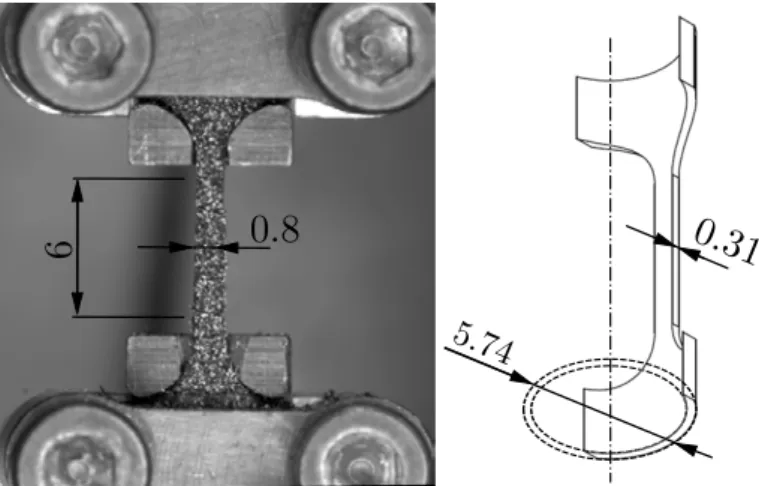
In this study, NiTi tubes were provided by Minitubes (Grenoble, France), with a 67
nominal composition of Ti-50.8 at.% Ni. Tubes were obtained by the cold drawing process. 68
The end tube dimensions are the result of a series of drawing passes through different 69
die/mandrel sizes in order to progressively reduce the inner and outer diameters [15, 16]. 70
The tube has an outer diameter of φext = 5.74 mm and a wall thickness of t = 0.31 mm.
71
From as-received cold-worked tubes, tubular samples of l = 5 mm length were cut using a 72
diamond saw. 73
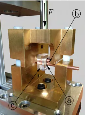
A DC Hughes Model VTA-60 resistance welder was used. The welding set-up is il-74
lustrated in Fig. 2. Two cylindrical copper electrodes of 4 mm diameter and 20 mm long 75
were used to clamp the tubular samples together. A plexiglas template ensured the tube 76
position and alignment. Resistance welding was carried out in an argon atmosphere using 77
an electrical pulse energy of E = 145 J and a contact force of F = 100 N. Each weld was 78
done in a single step. The weld line was well distributed along the length of the tube and 79
approximately 0.5 mm wide, observed in a scanning electron microscope. Two cellular 80
structures, named here square (Fig. 7a) and triangular (Fig. 8a), were fabricated and aged 81
at T = 350◦C for 60 min after welding. For further details on the effect of aging treatment 82
on the transformation behavior and on deformation behavior of Ni-rich alloys, see [17] and 83
[18]. 84
3. Experimental results and Analysis 85
3.1. Thermal transformation behavior 86
The thermal transformation behavior of cold-worked material and samples aged at 87
350◦C for 60 min were determined by differential scanning calorimetry, using a DSC Q200 88
V24.4 instrument. The heating and cooling rates were set at 10◦C/min. All measurements 89
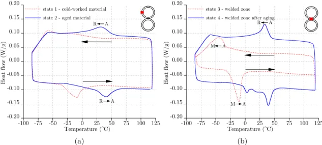
started with heating from T = 40◦C. Fig. 3 shows the DSC curves of the cold-worked 90
and the aged samples for two different zones. Fig. 3a was obtained with DSC specimens 91
taken far from the welded joint. Fig. 3b represents DSC specimens in the welded joint. 92
Thus, four different states are defined: state 1, the cold-worked material; state 2, the aged 93
material; state 3, the welded zone before aging; state 4, the welded zone after aging. For 94
state 1, the peaks have a low intensity. This is consistent with previous studies for cold-95
worked NiTi [19, 20]. State 2 exhibits flat but distinguishable A-to-R during cooling and 96
R-to-A during heating transformation peaks above room temperature. The R-to-M and 97
M-to-R transformations are undetectable due to their extremely low intensities or their 98
low temperatures. Concerning states 3 and 4 nothing can be precisely concluded since the 99
DSC samples are not homogeneous over the welded zone. The austenite finish temperature 100
(Af) was determined to be under 60◦C in all states.
101
3.2. Uniaxial tensile tests 102
In order to determine the mechanical behavior of tube specimens, uniaxial tensile 103
tests were performed on small dog-bone shaped specimens machined from the tubes by 104
spark cutting. The samples had an initial gage length l0 = 6 mm, width w0 = 0.8 mm and
105
thickness t0= 0.31 mm, as shown in Fig. 4. All tests on the following were performed using
106
a Gabo Explorer testing machine with a ±500 N load cell and with specially designed grips. 107
The testing temperature was controlled using a furnace in air with fanned convection 108
with an accuracy of ±1◦C. In all cases, the testing temperature was approached by 109
cooling from a temperature higher than 60◦C. Test images were recorded at 10 Hz with 110
a Jai TM-4200GE CCD 1024 × 1024 pixel camera and the spatial resolution achieved 111
for digital image correlation (DIC) was 0.05 mm. Strain was calculated by averaging 112
the strain field over the gage zone. The tests were performed at a global strain rate of 113
10−5s−1. Strain fields were calculated for the sequence of images corresponding to loading 114
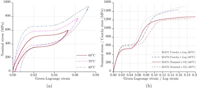
and unloading. Fig. 5a shows the nominal stress-strain first load-unload curves of the 115
uniaxial sample tested at 60, 70 and 80◦C. The effect of the testing temperature on critical 116
stresses for the forward and the reverse transformations was found to follow the Clausius-117
Clapeyron relationship with a slope close to 6.5 MPa/◦C. The samples tested above 60◦C 118
demonstrated pseudoelastic behavior, recovering any minor remaining deformation upon 119
heating. Fig. 5b shows the transformation and plastic strain until failure at 60◦C for a 120
sample aged at 350◦C for 60 min (MAT1), with the sample solution treated at 850◦C for 121
60 min followed by a 350◦C for 60 min aging (MAT2). Note that results were expressed 122
in terms of logarithm and Green-Lagrange strains measures and their respective stresses. 123
These results will be used to model the plastic behavior of tubes. For simplicity, we assume 124
negligible temperature effects in the plastic hardening curves. The uniaxial behavior 125
of MAT2 will be used to approximate the mechanical behavior of welded zones (WZs). 126
Indeed, as pointed out in [14], the microstructures of a heat treated (solution treated 127
and aged) and weld fusion zone are very similar. They contain large grains with almost 128
identical shape and size. 129
3.3. Radial compression test of a single tube 130
Research on the large deformation behavior of NiTi tubes under quasi-static radial 131
compression is not new in the literature. This type of test was used, for example, by [21] 132
in the design of passive vibration isolation. [22] performed radial compression of tubes 133
with different diameter-wall thickness ratios (φext/t). They highlighted the “giant
supere-134
lasticity effect”, that combines the geometry effect, expressed by the φext/t ratio, and the
135
intrinsic properties of NiTi SMA. [23] conducted a systematic investigation on deformation 136
behavior and influences of geometric dimensions for different boundary constraints. 137
In the present work, tubular samples of l = 5 mm length were radially loaded between 138
steel platens without lubrication. The lower head was fixed and the upper one was the 139
loading head moving at 0.1 mm/s. Force and displacement sensors recorded the force-140
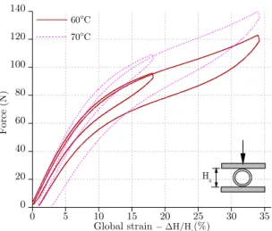
displacement curves, presented in Fig. 6, at 60 and 70◦C. 141
3.4. Radial compression test of tube stackings 142
Compressive quasi-static loading was applied to the tube stacking with a constant 143
crosshead velocity of 0.1 mm/s. Three loading-unloading cycles were successively per-144
formed at 4 %, 8 % and 12 % global strain (εg= ∆H/H0) for both cellular structures. No
145
damage of welded zones (WZs) was observed at this deformation level. Stress concentra-146
tion and localized plasticity phenomena induced by the stacking geometry could result 147
in different and more complex material behavior for tube stackings compared to single 148
tubes. Figs. 7 and 8 present the undeformed configuration and deformed shapes recorded 149
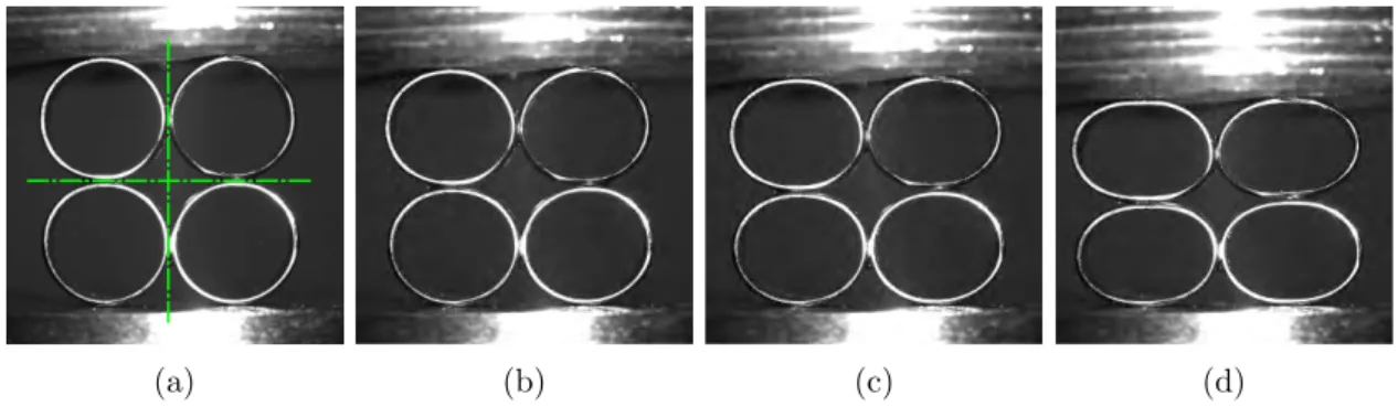
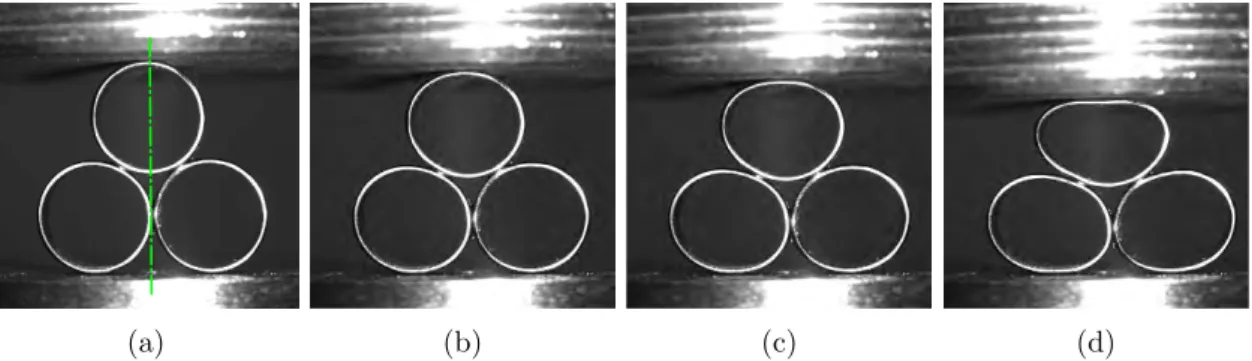
by a visible CCD camera at T = 23◦C. The deformation mode for the square sample is 150
symmetric with respect to the vertical and horizontal axes, whereas the triangular sample 151
is symmetric only with respect to the vertical axis, and the deformation appears to be 152
concentrated on the upper tube. 153
Fig. 9 shows the load-deformation curves for the two samples before weld damage for 154
three temperatures. The maximum global compression strain imposed is 12% in both 155
cases. Stiffness is higher for the square sample than for the triangular one, whereas the 156
hysteretic loops are quite similar. 157
4. Finite element simulations 158
4.1. Modeling of the experimental results 159
Nonlinear finite element simulations were performed to analyze the deformation behav-160
ior of NiTi tube structures. The Abaqus commercial finite element code was used with a 161
user material routine (UMAT) that follows the model proposed by [24]. This constitutive 162
model reproduces some basic features of shape-memory alloys at finite strains. The model 163
is based on an additive strain decomposition in which the total strain is taken as the sum of 164
the elastic strain, the transformation strain, and the plastic strain. Plastic strains develop 165
as soon as the material is loaded beyond full transformation. The work-hardening behavior 166
is assumed to exhibit tension-compression symmetry. A comprehensive treatment would 167
require knowledge of the complete yield envelope and the work-hardening characteristics 168
as a function of the stress state. 169
The material data required by the model are obtained only from observations of the 170
uniaxial tensile tests performed in Section 3.2. The data characterize the start and end 171
of the phase transformation during loading, unloading and reverse loading. The different 172
elastic constants for the austenite and martensite phases are taken into account. Temper-173
ature effects are included as well. In this work, no volumetric transformation strains are 174
considered. Many authors [25, 26, 27] have found asymmetries of transformation stress 175
and transformation strain between tension and compression. The start of transformation 176
stress during loading in compression, is reported to be around 30% greater than start of 177
transformation stress during loading in tension. For comparison, the tension-compression 178
asymmetry is considered only in the single tube model. Table 1 presents two sets of pa-179
rameters to model the material for the tube wall (MAT1) and the welded zone material 180
(MAT2), respectively. Table 2 presents the stress-strain points that define the yield curves. 181
All parameters are expressed in terms of Cauchy stress and logarithm strain measure. 182
Fig. 10a compares the finite element predicted curves to the experimental uniaxial 183
tensile tests. A good match with the experimental data is obtained when the temperature 184
effects are included. A continuum 8-node biquadratic plane strain fully integrated element 185
(CPE8) was used for single tube, square and triangle models. The mesh sensitivity was 186
first assessed by running multiple simulations with gradual mesh size refinement. The 187
mesh size was selected after which the results showed mesh independence. All elements 188
were chosen to be close to a square, insofar as possible, in undeformed configuration. For 189
all subsequent analysis 18 Gauss integration points over the tube thickness were used. 190
This ensured that the results were independent of the mesh geometry even though some 191
small differences can be noted at singular points. A flat analytical rigid surface was used 192
to represent the compression platens. The hard contact pressure-overclosure relationship 193
was used to define the finite-slide contact interaction between platens and tubes. Zero-194
penetration condition was enforced by an augmented Lagrange iteration scheme that drives 195
down the penetration distance. For simplicity, a frictionless behavior is assumed. These 196
same contact settings were used to define the self-contact between neighboring tubes during 197
stacking compaction. 198
Simulation results for a single tube compression (Fig. 10b) and both architectures, i.e., 199
square (Fig. 10c) and triangle (Fig. 10d), are also superimposed with the experimental 200
data. It is noted that the predicted results for a single tube compression (Fig. 10b) were 201
stiffer than the experimental curve. This difference further increased when a tension-202
compression dissymmetry of 20% was considered. The difference between experimental 203
and model results could be explained by the fact that undeformed tubes did not have a 204
perfectly cylindrical shape (straightness imperfections). Then the contact surface of the 205
tube, especially in the first load increments (until 5%), was not uniform. The effects of this 206
type of small imperfection tended to decrease, i.e., to be averaged when more tubes were 207
added, as in the case of the Figs. 10c and 10d. Even with all precautions taken to align 208
tubes during welding, a small discrepancy resulting from tube misalignment can also occur. 209
On one hand, work on small samples increases the sensitivity to defects and makes the 210
comparison between the modeling and experimental results more difficult. On the other 211
hand, it is important to keep in mind the simplicity of the constitutive model. Fig. 10 212
shows relatively close agreement between the experimental data and FEA predictions for 213
all cases. However, for larger strain levels, the predicted hysteresis overestimated the 214
experimental hysteresis. 215
These first results provide information on the respective contributions of both constitu-216
tive material properties and architecture of the cellular structure on its effective behavior. 217
The balance between these two contributions varies according to deformation level and 218
the type of architecture. 219
4.2. Role of the modeling in the design of superelastic cellular NiTi tube-based materials 220
In order to illustrate the possibility of using the previous results to gain a grater insight 221
into the role of the architecture and boundary conditions, two large cell structures shown 222
in Figs. 11 and 12 are modeled: a 6×6 square stacking and a 5(4)×6(3) hexagonal stacking, 223
containing approximately the same number of tubes. The influence of boundary conditions 224
was also evaluated using two different compression platen geometries. In the first load 225
case, flat platens were modeled by an analytical rigid surface, as shown in Fig. 11. In the 226
second load case, an analytical rigid surface composed of semicircles was used to model 227
grooved platens, as shown in Fig. 12. The compression mechanical responses of square and 228
hexagonal stackings, with the two different loading cases, are plotted in Fig. 13. 229
Due to symmetry, only one-quarter of the stackings were simulated, while applying 230
planar boundary conditions on symmetrical faces. The results were mirrored in the sym-231
metry planes. Figs. 11a, 11b, 12a and 12b show the undeformed configurations (in solid 232
lines) and the deformed configurations (Mises equivalent stress field) under imposed dis-233
placement, resulting in 5% of global strain in all cases. The computed deformed shapes 234
exhibited a stress concentration along the weld fillet. No adaptive remeshing procedure 235
was applied. 236
For the first load case (flat platens), no horizontal forces occurred in the square staking 237
(Fig. 11a) since no friction was considered. The maximum strain of εg = 5% was not
238
sufficient to activate phase transformation. Thus, no hysteresis was observed in the force 239
vs. global strain curve in Fig. 13. In the hexagonal structure (Fig. 11b), the upper and 240
lower layers moved horizontally, causing a strong deformation localization on these layers. 241
In the second load condition (grooved platens), Fig. 12a shows that square stacking 242
attained a barrel shape. This was due to horizontal forces which were not constant over 243
the entire cross section of the specimen. However, a more uniform force distribution on 244
the tube-wall network was obtained for hexagonal stacking using grooved platens. 245
The modeling results show that a more uniform force distribution was obtained us-246
ing flat platens for the square stacking and grooved platens for the hexagonal stacking. 247
Considering the compression mechanical behavior in Fig. 13, both architectures are fully 248
recovered after load removal. This suggests that most of the integration points are in the 249
pseudo-elastic regime. It is interesting to note that the hexagonal stacking is stiffer than 250
the square one for both load cases. This is in agreement with previously reported data 251
[13] for a different constitutive material. In addition, higher hysteresis is obtained with 252
hexagonal stacking. 253
The analysis was then extended by isolating a single tube from each architecture con-254
sidering the second load case using grooved platens. Figs. 12c and 12d show, in detail, 255
the equivalent strain in these tubes chosen near to the symmetry planes. This precau-256
tion is especially necessary to avoid border effects and ensure a periodic circumferential 257
strain distribution. The results shown in Figs. 12c and 12d suggest that the numbers of 258
martensitic transformation hinges (THs) are equal to the number of WZs and they are 259
located symmetrically on the circumference of the tube. Comparing both architectures, it 260
is possible to observe that when the number of WZs increases over the tube circumference 261
the arc-length of cell wall decreases, causing the structure to become stiffer. At the same 262
time, it also increases the level of cell wall bending. 263
The contour plot of the equivalent strain is shown in Figs. 12c and 12d at the moment 264
of maximum global strain (εg = 5%). In the square stacking, the maximum strain is less
265
than 5%. Only a few parts of the tube near WZs experienced a phase transition and THs 266
were not fully developed. For the same global strain level, the hexagonal stacking shows a 267
maximum local strain of about 8.15% in WZ2 and WZ5. Six THs seem to be formed, but
268
only four (TH2, TH3, TH5 and TH6) show local strains greater than the transformation
269
strain εl = 0.04 defined in Table 1. In both architectures, no plasticity was induced since 270
the local strains were less than those that define the beginning of the yield curve in Table 2. 271
Figs. 12c and 12d reveal that bending deformation can also activate stress-induced 272
martensitic phase transformation in WZs. This effect is more evident in certain WZs: 273
WZ1 and WZ3 for square stacking and WZ2 and WZ5 for hexagonal stacking. Otherwise,
274
transformation can be attributed to stress concentration on the WZs neighborhood: WZ2
275
and WZ4 for square stacking and WZ1, WZ3, WZ4 and WZ6 for hexagonal stacking.
276
This suggests that the geometrical disposition between WZs and THs zones as well as the 277
martensite volume fraction of each zone are important. Thus, some welded zones can also 278
contribute with the overall structure hysteresis. 279
5. Conclusions 280
Modeling is very useful for designing and optimizing architectured materials. In this 281
paper, the mechanical superelastic behavior of NiTi architectured tube-based NiTi mate-282
rials subjected to quasi-static compression was studied using two simple cellular samples. 283
This study demonstrated that resistance welding is a feasible technique to obtain architec-284
tured materials consisting of NiTi with low density and high reversible pseudo-elasticity. 285
All the samples can practically recover their initial shape during unloading in the exper-286
imental load range, and the load-displacement curves appear as hysteretic superelastic 287
loops, which are related to reversible austenite-martensite phase transformation. These 288
first results provide information on the respective contributions of the constitutive material 289
properties and architecture of the cellular structure on its effective behavior. The balance 290
between these two contributions varies according to the stress-strain level. Further work 291
to optimize the architecture, thermal treatment and process parameters is ongoing using 292
the experimental and modeling approaches described in the present paper. 293
Acknowledgment 294
The authors wish to acknowledge the financial support of the French ANR research 295
program ANiM: Architectured NiTi Material (N.2010 BLAN 90201). 296
References 297
[1] Stoeckel D. Shape memory actuators for automotive applications. Mater Des 1990;11:302–7. 298
[2] McDonald Schetky L. Shape memory alloy applications in space systems. Mater Des 1991;12:29–32. 299
[3] Morgan N. Medical shape memory alloy applicationsthe market and its products. Mater Sci Eng, A 300
2004;378:16–23. 301
[4] Mohd Jani J, Leary M, Subic A, Gibson MA. A review of shape memory alloy research, applications 302
and opportunities. Mater Des 2014;56:1078–113. 303
[5] Weinert K, Petzoldt V. Machining of NiTi based shape memory alloys. Mater Sci Eng, A 2004;378:180– 304
4. 305
[6] de Ara´ujo C, da Silva N, da Silva M, Gonzalez C. A comparative study of Ni–Ti and Ni–Ti–Cu shape 306
memory alloy processed by plasma melting and injection molding. Mater Des 2011;32:4925–30. 307
[7] Wu M. Fabrication of nitinol materials and components. In: Materials Science Forum. Trans Tech 308
Publication 2002;394:285–92. 309
[8] Ashby M. Designing architectured materials. Scripta Mater 2013;68:4–7. 310
[9] Grummon DS, Shaw JA, Foltz J. Fabrication of cellular shape memory alloy materials by reactive 311
eutectic brazing using niobium. Mater Sci Eng, A 2006;438-440:1113–8. 312
[10] Okabe Y, Minakuchi S, Shiraishi N, Murakami K, Takeda, N. Smart honeycomb sandwich panels 313
with damage detection and shape recovery functions. Adv Compos Mater 2008;17:41–56. 314
[11] Hassan M, Scarpa F, Ruzzene M, Mohammed N. Smart shape memory alloy chiral honeycomb. Mater 315
Sci Eng, A 2008;481:654–7. 316
[12] Ghosh P, Rao A, Srinivasa AR. Design of multi-state and smart-bias components using shape memory 317
alloy and shape memory polymer composites. Mater Des 2013;44:164–71. 318
[13] Marcadon V, Davoine C, Passilly B, Boivin D, Popoff F, Rafray A, Kruch S. Mechanical behaviour 319
of hollow-tube stackings: Experimental characterization and modelling of the role of their constitutive 320
material behaviour. Acta Mater 2012;60:5626–44. 321
[14] Delobelle V, Delobelle P, Liu Y, Favier D, Louche H. Resistance welding of NiTi shape memory alloy 322
tubes. J Mater Process Tech 2013;213:1139–45. 323
[15] Palengat M, Chagnon G, Favier D, Louche H, Linardon C, Plaideau C. Cold drawing of 316L stainless 324
steel thin-walled tubes: Experiments and finite element analysis. Int J Mech Sci 2013;70:69–78. 325
[16] Linardon C, Favier D, Chagnon G, Gruez B. A conical mandrel tube drawing test designed to assess 326
failure criteria. J Mater Process Tech 2014;214:347–57. 327
[17] Zhenga Y, Jianga F, Li L, Yang H, Liu Y. Effect of ageing treatment on the transformation behaviour 328
of Ti–50.9 at.% Ni alloy. Acta Mater 2008;56:736–45. 329
[18] Jiang F, Liu Y, Yang H, Li L, Zheng Y. Effect of ageing treatment on the deformation behaviour of 330
Ti–50.9 at.% Ni. Acta Mater 2009;57:4773–81. 331
[19] Frick CP, Ortega AM, Tyber J, Maksound A, Maier HJ, Liu Y, Gall K. Thermal processing of 332
polycrystalline niti shape memory alloys. Mater Sci Eng, A 2005;405:34–49. 333
[20] Sharifi EM, Karimzadeh F, Kermanpur A. The effect of cold rolling and annealing on microstruc-334
ture and tensile properties of the nanostructured Ni50Ti50 shape memory alloy. Mater Sci Eng, A 335
2014;607:33–7. 336
[21] Khan MM, Mayes JJ, Systems A, Helicopter B, Worth F, Henderson BK. Pseudoelastic SMA spring 337
elements for passive vibration isolation, Part I: Modeling. J Intel Mater Sys Str 2004;15415–41. 338
[22] Rivin E, Sayal G, Johal P. Giant superelasticity effect in NiTi superelastic materials and its applica-339
tions. J Mater Civil Eng 2006;18:1–7. 340
[23] Ke Z, Huijie Z, Zhiping T. Experimental study of thin-walled NiTi tubes under radial quasi-static 341
compression. J Intel Mater Sys Str 2001;22:2113–26. 342
[24] Auricchio F, Taylor R. Shape-memory alloys: modelling and numerical simulations of the finite-strain 343
superelastic behavior. Comput Methods Appl Mech Eng 1997;143:175–94. 344
[25] Org´eas L, Favier D. Stress-induced martensitic transformation of a NiTi alloy in isothermal shear, 345
tension and compression. Acta Mater 1998;46:5579–91. 346
[26] Lim T, McDowell D. Mechanical behavior of an Ni-Ti shape memory alloy under axial-torsional 347
proportional and nonproportional loading. J Eng Mater Tech 1999;121:9–18. 348
[27] Gall K, Sehitoglu H. The role of texture in tension-compression asymmetry in polycrystalline NiTi. 349
Int J Plast 1999;15:69–92. 350
a b
c
Figure 1: Some architectured material examples: (a) superelastic Nitinol honeycomb structure [9]; (b) SMA chiral honeycomb using NiTi ribbons [11]; and (c) Inconel R 600 architectured cellular material processed using a brazing heat treatment [13].
b
a
c
F
- 1 0 0 - 7 5 - 5 0 - 2 5 0 2 5 5 0 7 5 1 0 0 1 2 5 - 0 . 2 0 - 0 . 1 5 - 0 . 1 0 - 0 . 0 5 0 . 0 0 0 . 0 5 0 . 1 0 0 . 1 5 0 . 2 0 A R A state 1 - cold-worked material state 2 - aged material
H ea t f lo w (W /g ) Temperature (°C) R (a) - 1 0 0 - 7 5 - 5 0 - 2 5 0 2 5 5 0 7 5 1 0 0 1 2 5 - 0 . 2 0 - 0 . 1 5 - 0 . 1 0 - 0 . 0 5 0 . 0 0 0 . 0 5 0 . 1 0 0 . 1 5 0 . 2 0
state 3 - welded zone state 4 - welded zone after aging
H ea t f lo w (W /g ) Temperature (°C) A R A M A M (b)
Figure 3: Thermal transformation behavior of Ti-50.8 at.% Ni for (a) zone far from the welded joint and (b) welded zone. In both cases, samples were examined before and after aging treatment at 350◦C for 60 min.
6
0.8
5.74
0.31
0 . 0 0 0 . 0 2 0 . 0 4 0 . 0 6 0 . 0 8 0 2 0 0 4 0 0 6 0 0 8 0 0 1 0 0 0 60°C 70°C 80°C N om in al s tr es s (M Pa ) Green-Lagrange strain (a) 0 . 0 0 0 . 0 2 0 . 0 4 0 . 0 6 0 . 0 8 0 . 1 0 0 . 1 2 0 . 1 4 0 . 1 6 0 . 1 8 0 . 2 0 0 2 0 0 4 0 0 6 0 0 8 0 0 1 0 0 0 1 2 0 0 1 4 0 0 1 6 0 0
MAT1 Cauchy x Log (60°C) MAT2 Cauchy x Log (60°C) MAT1 Nominal x GL (60°C) MAT2 Nominal x GL (60°C) N om in al s tr es s / Ca uc hy s te ss (M Pa )
Green-Lagrange strain / Log strain
(b)
Figure 5: Nominal stress-strain curves resulting from tensile tests: (a) influence of the test temperature during loading and unloading at T = 60, 70 and 80◦C; (b) Ultimate tensile strength at 60◦C for the specimen aged at 350◦C for 60 min (MAT1) and specimen solution treated at 850◦C for 60 min followed by 350◦C for 60 min aging (MAT2).
0 5 1 0 1 5 2 0 2 5 3 0 3 5 0 2 0 4 0 6 0 8 0 1 0 0 1 2 0 1 4 0 60°C 70°C Fo rc e (N ) Global strain H/H0(%) H0
Figure 6: Force vs. global strain (εg = ∆H/H0) response at T = 60◦C and 70◦C of radially loaded superelastic NiTi tube φext= 5.74 mm at a loading rate 0.1 mm/s.
(a) (b) (c) (d)
Figure 7: Visible CCD images of a square sample at T = 23◦C under quasi-static compression at a loading rate of 0.1 mm/s. (a) undeformed configuration with initial length H0 = 11.48 mm,(b) εg = 4 %, (c) εg = 8 % and (d) εg= 12 %.
(a) (b) (c) (d)
Figure 8: Visible CCD images of a triangular sample at T = 23◦C under quasi-static compression at a loading rate of 0.1 mm/s. (a) undeformed configuration with initial length H0= 10.71 mm, (b) εg = 4 %, (c) εg= 8 % and (d) εg = 12 %.
0 2 4 6 8 1 0 1 2 0 2 0 4 0 6 0 8 0 1 0 0 1 2 0 1 4 0 1 6 0 1 8 0 2 0 0 2 2 0 70°C 60°C 23°C Fo rc e (N ) Global strain H/H0(%) H0 (a) 0 2 4 6 8 1 0 1 2 0 2 0 4 0 6 0 8 0 1 0 0 1 2 0 1 4 0 1 6 0 1 8 0 2 0 0 2 2 0 70°C 60°C 23°C Fo rc e (N ) H0 Global strain H/H0(%) (b)
Figure 9: Load-deformation curves: (a) square sample under compression; (b) triangular sample under compression.
0 . 0 0 0 . 0 1 0 . 0 2 0 . 0 3 0 . 0 4 0 . 0 5 0 . 0 6 0 1 0 0 2 0 0 3 0 0 4 0 0 5 0 0 6 0 0 7 0 0 8 0 0 UNIAXIAL EXP (70°C) UNIAXIAL FEA (70°C) UNIAXIAL EXP (60°C) UNIAXIAL FEA (60°C) N om in al s tr es s (M Pa ) Green-Lagrange strain (a) 0 5 1 0 1 5 2 0 2 5 3 0 3 5 0 2 0 4 0 6 0 8 0 1 0 0 1 2 0 1 4 0
SINGLE TUBE EXP (60°C) SINGLE TUBE FEA (60°C)
SINGLE TUBE FEA (60°C/30% DISSYMETRY)
Fo rc e (N ) Global strain H/H0(%) (b) 0 2 4 6 8 1 0 1 2 0 4 0 8 0 1 2 0 1 6 0 2 0 0 MAT2 SQUARE EXP (60 °C) SQUARE FEA (60 °C) Fo rc e (N ) Global strain H/H0(%) MAT1 (c) 0 2 4 6 8 1 0 1 2 0 4 0 8 0 1 2 0 1 6 0
2 0 0 TRIANGLE EXP (60 °C) TRIANGLE FEA (60 °C)
Fo rc e (N ) Global strain H/H0(%) (d)
Figure 10: Comparison of experimental (EXP, red curves) and finite element analysis (FEA, blue curves) results at T = 60◦C. (a) uniaxial tensile test used for parameter identification; (b) compression behavior of a single tube; (c) compression behavior of square sample with a mesh detail of the welded zone; (d) compression behavior of a triangular sample.
(a) (b)
Figure 11: Equivalent Mises stress field of (a) 6×6 square stacking (36 tubes) and (b) 5(4)×6(3) hexagonal stacking (38 tubes), using flat platens. The undeformed configuration is superimposed by solid lines.
(a) (b) WZ2 WZ4 WZ1 WZ3 TH1 TH2 TH3 TH4 (c) WZ1 WZ2 WZ3 WZ4 WZ5 WZ6 TH2 TH3 TH4 TH5 TH6 TH1 (d)
Figure 12: Finite element results of 6 × 6 square stacking (36 tubes) and a 5(4) × 6(3) hexagonal stacking (38 tubes) using grooved platens. (a) and (b) equivalent Mises stress field. Undeformed configuration is superimposed by solid lines. (c) and (d) detail of unity tube showing the equivalent strain field for square and hexagonal stackings respectively. Welded zones (WZs) and transformation hinges (THs) are also indicated. The undeformed configuration is superimposed in gray.
0 1 2 3 4 5 0 2 5 0 5 0 0 7 5 0 1 0 0 0 1 2 5 0 1 5 0 0 1 7 5 0 S Q U A R E - 6 x 6 ( f l a t p l a t e n ) H E X A - 5 ( 4 ) x 6 ( 3 ) ( f l a t p l a t e n ) S Q U A R E - 6 x 6 ( c u r v e r d p l a t e n ) H E X A - 5 ( 4 ) x 6 ( 3 ) ( c u r v e d p l a t e n ) Fo rc e (N ) G l o b a l s t r a i n H / H 0( % )
Table 1: Values of the constitutive equation parameters (Auricchio’s model in Abaqus UMAT)
Parameter Unit MAT1 MAT2
Austenite Young’s modulus (Ea) GPa 60 40
Austenite Poisson’s ratio (νa) - 0.33 0.33
Martensite Young’s modulus (Em) GPa 25 20
Austenite Poisson’s ratio (νa) - 0.33 0.33
Transformation strain (εl) - 0.04 0.05
Clausius-Clapeyron relationship (∂σ/∂T ) MPa/◦C 6.5 6.5 Start of transformation loading (σsl) MPa 500 600
End of transformation loading (σle) MPa 580 720
Reference temperature (T ) ◦C 60 60
Start of transformation unloading (σsu) MPa 390 400 End of transformation unloading (σeu) MPa 240 350
Table 2: Stress-strain points in the yield curve (Auricchio’s model in Abaqus UMAT) MAT1 MAT2 εn σnp( MPa) εn σpn( MPa) 0.067 1018.0 0.093 1206.9 0.071 1078.8 0.097 1253.3 0.075 1152.1 0.101 1289.1 0.087 1261.9 0.104 1308.7 0.100 1324.4 0.110 1329.0 0.112 1368.4 0.117 1354.3 0.124 1402.4 0.126 1380.1 0.136 1436.3 0.134 1400.4 0.148 1469.4 0.143 1419.4 0.177 1524.3 0.159 1449.3
![Figure 1: Some architectured material examples: (a) superelastic Nitinol honeycomb structure [9]; (b) SMA chiral honeycomb using NiTi ribbons [11]; and (c) Inconel R 600 architectured cellular material processed using a brazing heat treatment [13].](https://thumb-eu.123doks.com/thumbv2/123doknet/14426732.514361/13.892.167.763.109.295/architectured-superelastic-honeycomb-structure-honeycomb-architectured-processed-treatment.webp)