HAL Id: hal-00997765
https://hal.archives-ouvertes.fr/hal-00997765
Submitted on 28 May 2014HAL is a multi-disciplinary open access
archive for the deposit and dissemination of sci-entific research documents, whether they are pub-lished or not. The documents may come from teaching and research institutions in France or abroad, or from public or private research centers.
L’archive ouverte pluridisciplinaire HAL, est destinée au dépôt et à la diffusion de documents scientifiques de niveau recherche, publiés ou non, émanant des établissements d’enseignement et de recherche français ou étrangers, des laboratoires publics ou privés.
Experimental investigation of an innovative
thermochemical process operating with a hydrate salt
and moist air for thermal storage of solar energy: global
performance
Benoit Michel, Pierre Neveu, Nathalie Mazet
To cite this version:
Benoit Michel, Pierre Neveu, Nathalie Mazet. Experimental investigation of an innovative thermo-chemical process operating with a hydrate salt and moist air for thermal storage of solar energy: global performance. Applied Energy, Elsevier, 2014, 129, pp.177-186. �10.1016/j.apenergy.2014.04.073�. �hal-00997765�
1
Experimental investigation of an innovative thermochemical process
operating with a hydrate salt and moist air for thermal storage of solar
energy: global performance
Benoit Michela,*, Nathalie Mazeta,*, Pierre Neveua,ba
PROMES-CNRS, Tecnosud, Rambla de la thermodynamique, 66100 Perpignan, France
b
Université de Perpignan Via Domitia, 52 Av. Paul Alduy, 66860 Perpignan, France
Abstract: This paper investigates an innovative open thermochemical system dedicated to
high density and long term (seasonal) storage purposes. It involves a hydrate/water reactive pair and operates with moist air. This work focuses on the design of and experimentation with a large scale prototype using SrBr2/H2O as a reactive pair (400 kg of hydrated salt, 105
kWh of storage capacity and a reactor energy density of 203 kWh/m3). Promising conclusions have been obtained regarding the feasibility and performance of such a storage process. Hydration specific powers from 0.75 to 2 W/kg have been reached for a bed salt energy density of 388 kWh/m3. Moreover, two important parameters that control the storage system have been identified and investigated: the equilibrium drop and the mass flow rate of moist air. Both have a strong influence on the reaction kinetics and therefore on the reactor’s thermal power.
Keywords:
Thermochemical process, open sorption process, solid-gas reaction, hydration, thermal storage, seasonal storage, solar energy
* Corresponding author:
E-mail: mazet@univ-perp.fr
Nomenclature:
A affinity, J∙mol-1s Greek symbols cm heat capacity, J.kg
-1
.K-1 standard enthalpy of reaction, J∙mol-1s
Dec energy density of the reactive bed, J∙m-3 standard entropy of reaction, J∙mol-1s.K -1
Der energy density of the reactor, J∙m-3 thermal conductivity, W∙m-1.K-1 G reactive gas ν stoichiometric coefficient, molG/mols
HR relative humidity X advancement variation
K equilibrium constant Indices
k permeability, m2 0 dehydrated salt
M molar weight, kg∙mol-1 1 hydrated salt
m mass, kg a dry air Mass flow rate, kg.s-1 amb ambient
N mole quantity of salt, mol eqLG liquid/gas equilibrium p pressure, Pa eqSG solid / gas equilibrium ∆p pressure drop across the salt bed, Pa h moist air
reaction power, W i inlet of the porous bed
specific power, W.kg-1 j outlet of the porous bed S reactive solid r reaction
R gas constant, J∙mol-1.K-1 s salt
T temperature, K t total
2
flow rate, m3.h-1 X reaction advancement
w specific humidity, kgv.kga -1
Exponent
X reaction advancement 0 reference
1.
Introduction
The energy demand for buildings accounts for 25% of total energy consumption in the world and 40% in Europe. Space heating represents the main part of this energy: 53% in the world and about 80% in Europe [1]. The increasing scarcity and cost of fossil fuels and incentives to reduce greenhouse gas emissions have led to a growing interest in solar energy. Solar energy is widely affordable and has the capability to meet household demand over the year. Unfortunately, its intermittency and variability with weather conditions, time, and seasons lead to a mismatch between heating demand and solar energy availability. Thus, a key issue to maximize the use of solar energy for space heating is to valorize the excess solar energy in summer by implementing long-term storage (3–6 months). Such a seasonal storage system must have the lowest heat losses between summer and winter, and the highest energy density to reduce its size and cost.
Several studies have dealt with seasonal storage for residential applications [2,3]. Among available storage systems, a sorption process takes advantage of a high storage density (about 100 to 500 kWh∙m-3
of storage material), and weak heat losses between the storage and heating periods because the energy is stored as chemical potential and the sensible heat is weak. Therefore, such a system is relevant for seasonal storage for space heating for households. In comparison with competitive systems, the energy density is about 90 kWh∙m-3
for latent storage and about 54 kWh∙m-3
for water (sensible heat over ΔT=70 °C and 25% heat losses) [4].
Sorption processes are increasingly being investigated for storage purposes, either regarding reactive materials or the workings of the storage system [3]. Several prototypes of sorption storage have been experimented with [5–19] at a small scale; the largest is the SOLUX system, which stores 60 kWh [7]. Nevertheless, no large-scale seasonal project has yet been completed [20].
Let's recall that different energy densities can be defined for these systems, referring to volumes of active material only, or to the whole reactor implementing the active material and including dead volumes and volumes dedicated to heat and mass transfer within the reactor and the coolant loops (heat exchanger, gas diffuser, collector…). Figure 1 compares these two energy densities for most of the prototypes, referring to the reactive material (x-axis) and the whole reactor prototype volume (y-axis). The energy density of the prototypes is significantly less than the reactive material energy density, i.e. only about half.
3
Figure 1: Energy densities of various sorption storage prototypes as function of the energy density of the reactive materials implemented in the prototype: TCA (LiBr/H2O, [10]), HYDES and MODSTORE (Silica gel/H2O, [12,13]), SPF (Zeolithe 13X/H2O, [19]), MONOSORP (Zeolithe 4A/H2O, [14]), CETHIL
(MgSO4+Zeolithe 13X/H2O, [18]), SOLUX (SrBr2/H2O, [7]), ECN (MgCl2/H2O, [8]), and ESSI: the prototype
reported in this paper (SrBr2/H2O).
Among all these experiments, the highest values of the material and prototype energy densities are, respectively, 280 kWh∙m-3 for the reactive material and 140 kWh∙m-3
for the storage system. The work described in this paper aims at developing a solid/gas sorption storage system beyond this range and experimenting with it on a significant scale (about 1/10 the capacity of a long term storage system for house heating).
This thermochemical storage process involves a reversible chemical reaction between a solid and a gas (equation 1). The reaction is a hydration/dehydration and a well-known hydrate/water pair has been selected (equation 2). The synthesis (or hydration) of the solid is exothermic (destorage step), while its decomposition (or dehydration) requires heat input (storage step). A thermochemical process based on such a hydrate/water pair can operate according to two different modes: the salt can react with pure water vapor at low pressure or with a moist air flow at atmospheric pressure. The first working mode is standard and simple, and most thermochemical systems in the literature operate with pure vapor [6,7,12,16,17]. Nevertheless, this low pressure generates strong technological constraints for the reactor. On the other hand, the innovative operating mode with moist air allows a less expensive reactor conception [21] but its management is more complex. Only a few authors are currently investigating the feasibility and performances of systems running with moist air [8,15,22–25]. So far, the successful operation of a seasonal storage system based on a thermochemical process operating with moist air has never been demonstrated at the pilot-scale. This challenge is the reason for this study.
Therefore, a prototype thermochemical storage reactor operating with moist air has been designed and experimented. Several previous works and literature reports outlined the background of this study. There are summarized in the following:
Beside the high storage density criteria, a seasonal storage system also has to fulfill requirements about thermal power production in order to meet user demand during the
4 house heating (destorage) step. A previous simulation work using TRNSYS software and a large set of simulations and sensitivity studies reported and detailed in [26] defined this demand, its requirements and target values for the storage system. The main results of this study were: a thermochemical seasonal storage system involving 5 to 10 tons of SrBr2,6H2O
(1300–2600 kWh of storage capacity) could allow a fractional energy savings (i.e. rate of energy consumption reduction compared to conventional non-solar installation) of about 65% to be reached for typical houses [27] and French climates. Under such conditions this storage system should provide a thermal power from 3 to 4 kW. Thus, the required specific power at the reactor output was deduced: 0.3 to 0.8 W.kg-1. This specific power range is the target of the prototype developed in this study.
The strontium bromide/H2O reactive pair has already been successfully experimented
with in previous works [7,28]. Its ideal energy storage density is very high: 629 kWh∙m-3 (referring to the bulk density, 2390 kg∙m-3
, and the molar mass of non-porous hydrated salt, 0.3555 kg∙mol-1) [29]. Regarding the energy density related to the reactive bed volume, a previous experiment on a small scale [22] demonstrated that promising values, higher than 400 kWh/m3, can be reached, highlighting its suitability as a long term thermal storage system.
In an open thermochemical system operating with moist air, the total gas flow rate passing through the bed is high and mass transfers have to be carefully investigated. The permeability of the strontium bromide porous bed was measured in a dedicated experimental set-up over a large range of packing densities, including the bed density of the current prototype [22].
Then, a 2D model of such a thermochemical system was developed [30]. Simulations demonstrated that in the range of packing densities corresponding to seasonal storage, the two operating modes (with pure vapor or moist air) lead to closely similar values of thermal power at the reactor output. For both modes, the mean specific power value over the reaction is higher than the target value (0.3 to 0.8 W/kg) as long as the bed energy density is less than 410 kWh/m3.
Thus, an experimental study of a thermochemical storage system operating with moist air was performed. It aims at:
- demonstrating the feasibility of such a storage system at a pilot-scale,
- analyzing its capability to fulfill both energy density and specific output power criteria, and
- determining the parameters allowing control of the output performances of the storage system.
5
2.
Thermochemical system for thermal storage
2.1.
Solid/gas thermochemical process
A thermochemical system is based on the thermal effect of a monovariant reversible reaction between a solid and a gas:
(1) For the prototype under study, the strontium bromide/water reactive pair was used. The reaction is:
<SrBr2, 1H2O> + 5(H2O) ↔ <SrBr2, 6H2O> + Δh0r (2)
<SrBr2,1H2O> and <SrBr2,6H2O> are respectively the dehydrated (S0) and hydrated (S1)
salts, the reactive gas (G) is water and the stoichiometric coefficient ( ) is 5 molG/mols.
The equilibrium conditions (peqSG, TeqSG) of such solid/gas reactions follow the Clausius-Clapeyron relation:
(3)
p0 is the reference pressure (1 bar). The standard enthalpy and entropy of reaction have been measured [7] : =337000 J/mols and =875 J/K/mols (per mol of salt).
Thus, the thermodynamic equilibrium conditions are determined by only one intensive variable: the gas pressure peqSG or the temperature of the solid TeqSG. For the specific case of a thermochemical system operating with moist air at atmospheric pressure, the thermodynamic equilibrium conditions (Equation 2) are related to the partial pressure of water in moist air.
2.2.
Working mode of a thermochemical storage system with moist air
The seasonal thermochemical storage process for space heating works as follows:
- Initially, at the end of summer, the reactive bed is ideally fully dehydrated. The salt is SrBr2,1H2O
- During the heating period (winter): a flow of moist air passes through the reactor, and the dehydrated salt reacts with water vapor. Exothermic synthesis (hydration) occurs and the storage system releases heat to the user ( per mol of salt). At the end of this step, the salt bed is fully hydrated (SrBr2,6H2O).
- During the following storage period (summer): moist air is heated thanks to solar collectors, then this hot air flow passes through the porous bed of SrBr2,6H2O. That leads to an
endothermic decomposition reaction (dehydration) of the SrBr2,6H2O salt to SrBr2,1H2O.
- Between the storage and heating (destorage) periods, the reactor is closed and disconnected from the reactive gas flow, allowing the reaction heat to be stored over a long time. Heat losses are weak because they are linked to the sensible heat of the materials,
6 which is significantly less than the heat of reaction. Thus, a thermochemical process is particularly suitable for seasonal heat storage.
3.
Prototype design and experimental set up
3.1.
Reactor design
The thermochemical reactor prototype was designed and sized in order to achieve both criteria that define a seasonal storage system as described above: a high energy density and a specific power suitable for space heating for residential housing.
Various solid/gas reactor configurations have been proposed in the literature [31,32] : screw reactor, fluidized reactor, fixed bed reactor…. Nevertheless, according to PROMES laboratory knowledge [5–7,33,34], a simple and cheap reactor configuration involving a porous fixed bed of reactive solid was chosen for this experimentation.
The prototype was designed in a modular way by stacking eight rectangular modules filled with a fixed bed of reactive salt (Figure 2 and Figure 3). A ninth module was planned but finally not included due to manufacturing difficulties.
Both the top and bottom of each module are in contact with the moist air flow thanks to a 1.5 cm thick air blade which is used as a mass diffuser. Obviously, the diffuser volume diminishes the energy density of the reactor. In order to maximize the reactor energy density, the number of diffusers should be minimized by implementing thicker reactive beds. However, a high thickness can limit mass transfer and reduce the specific power delivered by the thermochemical reactor (the power decreases with the square of the bed thickness [22]). Thus, the thickness of the reactive bed is a key parameter in designing a thermochemical reactor and achieving a tradeoff between the two performance criteria.
A previous experimental study at small scale demonstrated that a reactive SrBr2 bed
featuring about 400 kWh/m3 of energy density and a thickness of 5–10 cm reached the target value of specific thermal power in the winter phase [22]. Thus, the thermochemical reactor prototype was designed with a reactive bed 7.5 cm thick and 388 kWh/m3 as the energy density. The other module dimensions (width: 65.1 cm, and depth: 69.4 cm, see Figure 2), were chosen in order to simplify the handling of the prototype. Each module contains 50 kg of hydrated salt; the whole prototype contains 400 kg of hydrated salt and can store 105 kWh.
The performance of this prototype has been assessed thanks to the simplified 1D model (sharp front model) developed and validated previously for similar reactive beds [22,35] and the permeabilities of the hydrated and dehydrated salt bed measured (k1 and k0, respectively,
see Table 1). The moist air flow rate through the bed is fixed at a constant value (300 m3/h). This set of operating and design conditions allows the storage reactor to supply a specific power matching the target range (see Table 1). Moreover, the chosen bed thickness leads to a pressure drop across the bed that can be technically managed easily (from 60 to 560 Pa, over the reaction).
7 Operating and design conditions (input data) Simulated performances k1 1012 m2 k0 1012 m2 Dec kWh/m3 pvi Pa m3/h Tc °C W/kg Δp Pa 59 570 388 700 to 1000 300 35 1 to 2.7 60 to 560
Table 1: Simulation of the working prototype using the sharp front model under winter (destorage) conditions: input data (reactive bed energy density, Dec, dehydrated and hydrated permeabilities, k0 and
k1, inlet water partial pressure, pvi, moist air flow rate, , and reaction temperature, Tc) and resulting
specific power ( ) and pressure drop across the bed (Δp).
The whole design of the prototype is described in Figure 2 and Figure 3.
On the bottom side of each module, a perforated plate and a metallic mesh avoid any salt losses, while the top side is free (Figure 2).
On one side of each reactive bed, a gas diffuser (3 cm width) connected to the reactor air inlet supplies moist air to the reactive salt. This air flows axially through the reactive bed, then is collected on the opposite side by an outlet air collector (Figure 3).
Finally, the prototype is insulated by a double layer of insulation: 5 cm of “Pyrogel XT 10“, =0.022 W∙m-1
.K-1, and 3.2 cm of “Armaflex AC“, =0.039 W∙m-1.K-1.
Figure 2: Module of the prototype a) Schematic overview of a module
b) Module before filling with salt, with two thermal probes. c) Module filled with salt
Perforated grid Métallic mesh Support Salt bed l’=65 cm L’=70 cm h’=8 cm
Hydrated salt bed a)
c) b)
Metallic tissue Thermocouples
8
Figure 3: Reactor prototype
a) Vertical section, including the air flow paths. b) Photography of the prototype before closing it.
The reactor prototype dimensions and characteristics are summarized in
Prototype
Reactor dimensions*, h x L x l (cm) 99.3x77.5x72*
Reactor external dimensions, h x L x l (cm) 130x106x90
Module dimensions, h’ x L’ x l’ (cm) 8x69.4x65.1
Air collector dimensions, h x L x l (cm) 99.3x3x72
Mass diffuser dimensions, h x L x l (cm) 1.5x69.4x65.1
Bed thickness, Zs (cm) 7.5
Mass of hydrated salt, m1 (kg) 400
Salt bed energy density, Dec (kWh∙m-3
) 388
Reactor energy density*, Der (kWh∙m-3
) 203*
Table 2. Excluding feet, insulation and the ninth module, the reactor energy density is 203 kWh/m3. Note that this value can easily be enhanced in an industrial manufacturing process by optimizing the moist air flow through the whole prototype and reducing the volumes devoted to air diffusers and collectors. The prototype channels are oversized, as standard components were used for the sake of simplicity.
The air input and output of this reactor are connected to an aeraulic bench test providing a controlled moist air flow (temperature, moisture, flow rate).
1 2 3 4 5 6 7 8 h=96,6 cm L=74,9 cm Air collector Modules 9 l=72 cm a) b) Air input Air output
9
Prototype
Reactor dimensions*, h x L x l (cm) 99.3x77.5x72*
Reactor external dimensions, h x L x l (cm) 130x106x90
Module dimensions, h’ x L’ x l’ (cm) 8x69.4x65.1
Air collector dimensions, h x L x l (cm) 99.3x3x72
Mass diffuser dimensions, h x L x l (cm) 1.5x69.4x65.1
Bed thickness, Zs (cm) 7.5
Mass of hydrated salt, m1 (kg) 400
Salt bed energy density, Dec (kWh∙m-3
) 388
Reactor energy density*, Der (kWh∙m-3
) 203*
Table 2: Geometric characteristics of the prototype. (* excluding feet, insulation and ninth module)
3.2.
Instrumentation and measurement uncertainties
The prototype was thoroughly instrumented at the following points in order to record the numerous variables and monitor the progress of the thermochemical reaction:
At the inlet and outlet air pipe: flow rate ( and , ±0.8 %), relative humidity (HRi and
HRj, ±0.8 %), and total pressure (pti and ptj, ±1 Pa).
Note that a chilled mirror hygrometer is used at the reactor outlet. It allows the moist air specific humidity (wj, ±0,20 K at the dew point measurement) to be measured with high accuracy, even when the value of the relative humidity is low, in the dehydration step.
At the reactor boundaries: the total pressure difference between the input and output of the reactor Δp ±20 Pa (differential pressure sensor), input/output moist air temperature Ti, Tj (PT100, ±0.2 K).
These measurements allow estimation of the reactor equivalent permeability, and the enthalpy balance of moist air flow between the reactor air input and output.
Within the reactor modules: 24 thermocouples are distributed in the salt beds (in modules 1, 3, 4, 5, 6 and 8), measuring axial and longitudinal temperature gradients across the salt layer. Several thermocouples located at the same position in all the modules permit temperature differences along the reactor axis to be evaluated. The temperature measurement uncertainties are ±0.3 K.
At ambiance: ambient relative humidity: HRamb ±0.8 %, ambient temperature: Tamb ±0.3 K, ambient total pressure: pamb ±1 Pa.
Additionally, the reactor was placed on a large scale and weighted continuously to measure the reaction advancement defined by equation 3 during the reaction.
10 (4)
Ns1,X the number of moles of hydrated salt in the reactor at the global advancement X,
Ns,t the total number of moles of salt.
ms0, ms1 and msX refer to the total mass of the reactor, when the salt is fully hydrated, dehydrated and at advancement X, respectively. The weight measure uncertainties are ±0.2 kg. X is 0 for the dehydrated solid and X=1 at the end of the hydration reaction.
From these measurements and using correlations based on the French standard NFX15-110 and the Ashrae Handbook Fundamentals [36], it is possible to calculate all the characteristics of the moist air flow (temperature, humidity, enthalpy, density, ...).
Measurements are recorded every 30 seconds. The results presented in the following sections are averaged values over 30 min of recorded data.
3.3.
Experimental operating conditions
The rate of reversible solid gas reaction strongly depends on the equilibrium drop, i.e. the difference between the operating temperature and pressure and equilibrium thermodynamic values defined by equation 2 [37,38].
Thus, for the hydration and dehydration steps the prototype was tested at two equilibrium drops, a high and a low value. The two sets of operating conditions are presented in a Clausius-Clapeyron diagram in Figure 4 and in Table 3 (temperature, water partial pressure, the corresponding specific humidity and affinity). These equilibrium drops were chosen to be in the range of moist air conditions that can be encountered by a seasonal storage process: the high equilibrium drop corresponds to standard operation of the reactor, while the low equilibrium drop corresponds to more restrictive operating conditions.
These equilibrium drops can be related to the affinity A by:
(5)
with pv the partial pressure of water, and peqSG the solid/gas equilibrium pressure at T. This
affinity is negative for dehydration conditions and positive for hydration, and increases with the equilibrium drop.
Hydration Dehydration High equilibrium drop Low equilibrium drop High equilibrium drop Low equilibrium drop Ti (°C) 25 25 82 62 pvi (Pa) 1 000 700 2 500 2 500 ωi (kgv.kg -1 a) 0,0062 0,0043 0,0157 0,0157 Affinity (J∙mol-1s) 19 040 14 620 -28 200 -7 650
11
Figure 4 : Experimental operating conditions for the reactor prototype based on the SrBr2,1-6H2O
reaction, in a Clausius-Clapeyron diagram.
4.
Experimental results
The thermochemical storage prototype was tested for five months. Seven hydration/dehydration cycles were performed and various operating parameters were applied. Figure 5 shows the progress of the reaction (X) as a function of time for these cycles. As the study focuses on a seasonal storage system, the cycle times are rather long (15 to 20 days for the high equilibrium drop), so only a few cycles could be performed during this five-month experiment. Moreover, the cycles were not completed ( X<1) because the kinetics decrease drastically at the very end of the reaction, so completing these reactions fully would lead to a too long experiment time.
The experimentations were mostly performed with a high equilibrium drop and a constant moist air flow rate (313 m3/h during dehydration, 290 m3/h during hydration).
In addition, the influence of these two parameters was investigated by experimenting with a variable flow rate (from 313 to 150 m3/h, cycles 6 and 7) and a variable equilibrium drop (alternately high and low value, cycle n°5).
Intermittent operation, including several days stopped, was also experimented with (cycles 3 and 4) in order to analyze the off-season operation of a seasonal storage system.
100 1000 10000 0 10 20 30 40 50 60 70 80 pv(Pa) Temperature (°C) Hydration High equilibrium drop Low equilibrium drop Dehydration High equilibrium drop Low equilibrium drop SrBr21-6 equilibrium H2O L/G equilibrium Saturated solution
12
Figure 5 : Advancement vs. time for seven cycles performed by the thermochemical storage reactor prototype.
The following sections analyze these experimental results in order to better understand the operation of the moist air thermochemical storage system and assess its global performance.
First, the performance of cycles operating under fixed conditions (a high equilibrium drop and constant flow rate) were analyzed (§ 4.1). Second, cycles run with variable operating conditions (flow rate, air temperature and humidity,...) were investigated in order to understand the dynamic influence of these parameters and ways to control the storage power and air temperature at the reactor outlet (§4.2).
4.1.
Global performance of the prototype
4.1.1. Reaction rate
Advancement as a function of time is shown in Figure 6a) and Figure 6b) for, respectively, hydration and dehydration, working at a high equilibrium drop. The operating conditions are listed in
Table 4.
First, Figure 6 shows that the kinetics is not constant over the reaction but decreases as the reaction progresses. This phenomenon is well-known for such solid/gas reactions.
Second, the performance changes significantly between each of the first four cycles. Reaction times at mid-reaction (X = 0.5) range from approximately 60 h for the first hydration to about 100 h for the fourth hydration. Similarly, during dehydration, the reaction time at X=0.5 changes from 35 h for the first dehydration to 55 h for the third. Thus, the mid-reaction time increases 1.7 fold for hydration and 1.6 for dehydration compared to the first cycle. However, from the sixth cycle on, the kinetics remained within this range: the mid-reaction time is 70 h and 40 h for, respectively, hydration and dehydration.
0 0,1 0,2 0,3 0,4 0,5 0,6 0,7 0,8 0,9 1 0 20 40 60 80 100 120 140 160 Advancement X Times (days) Stop step 10 days Stop step 5 days 1st 2nd 3rd 4th 5th 6th 7th ith Hydration/dehydration cycle
13
Table 4: Operating conditions of each reaction carried out at a high equilibrium drop and constant air flow rate. The difference between final and initial advancement of successive reaction corresponds to experimentations carried out with different operating conditions.
Figure 6: Experimental advancement vs. time for reactions at a high equilibrium drop and constant air flow rate: a) hydrations; b) dehydrations. Most of the reactions were not complete and begin at different advancements. Thus, the initial time of each reaction has been shifted in order to compare the set of hydrations and dehydrations to the first cycle in the same advancement range.
Therefore, despite the reaction rate evolution over the first cycles, the reaction kinetics seems to stabilize from the sixth cycle onward. This kinetics diminution followed by stabilization after a few cycles is a well-known effect for such solid/gas reactions [39]. It is usually explained by a change in the porous bed texture during the reaction due to the significant increase in the salt grain volume from the dehydrated to hydrated state, which causes strong mechanical stresses. Further experiments are in progress to measure this kinetics over a long period of time cycling at the prototype scale.
4.1.2. Thermal power of the prototype
0 0,1 0,2 0,3 0,4 0,5 0,6 0,7 0,8 0,9 0 50 100 150 200 250 0 0,1 0,2 0,3 0,4 0,5 0,6 0,7 0,8 0,9 1 0 20 40 60 80 100 Advancement Advancement Time (h) Time (h)
Hydrations
1st 2nd 3rd 4th 6th 7th Hydrations 1st 2nd 3rd 6th Dehydrations b) a)Dehydrations
(m3/h) initial / final 1st dehydration 80 2 557 312.6 1 / 0 1st hydration 25 997.5 289.6 0 / 0.58 2nd dehydration 77.9 2 570 311.2 0.57 / 0.2 2nd hydration 25 981 290 0.05 / 0.82 3rd dehydration 79.8 2 459 313 0.83 / 0.35 3rd hydration 25 944.7 290 0.14 / 0.82 4th hydration 24.9 982.2 290 0 / 0.8 6th dehydration 79.8 2 468.7 312.9 0.55 / 0.28 6th hydration 24.9 980.4 284.4 0.28 / 0.7 7th hydration 24.8 968.2 271.8 0.55 / 0.8914 This section deals with the thermal power released or consumed by the reaction (respectively, in hydration or dehydration). Thanks to the numerous sensors implemented in the prototype, it can be estimated in two ways. The first is based on the mass balance of the reactor and the second on the enthalpy balance of the moist air flow. Both methods are redundant as they lead to results within the same uncertainty range [30]. For the sake of simplicity, only the mass balance method is presented in this paper: The variation in the water contained in the salt over the reaction time is deduced from monitoring the mass of the reactor. The thermal power resulting from the reaction and the specific power can be expressed as:
(6)
(7)
With the salt mass variation during time, ms1 the mass of hydrated salt and Mv the water
molar mass.
Figure 7 presents the thermal power due to the reaction, , as a function of the advancement for several cycles operating at a high equilibrium drop and constant flow rate (see
Table 4). As discussed above, performances change significantly over the first four cycles. The reaction thermal power at X=0.5 is higher than 800 W for the first hydration and about 300 W for the fourth hydration. In dehydration, the reaction thermal power is higher than in hydration phase because of the larger equilibrium drop (Table 3). But the same power decrease occurs over the first cycles. At the sixth cycle, the thermal power increases and seems to become quite stable for hydration. At X=0.5 of the sixth cycle, the reaction power is -770 W in dehydration and 485 W in hydration. Further experimentations are in progress in order to validate the reaction rate stabilization over numerous cycles.
Regarding the specific power, the four first hydrations lead to values from 2 W/kg to 0.75 W/kg of hydrated salt (at X=0.5), and the sixth to 1.21 W/kg of hydrated salt. For dehydration, the specific power is higher: 1.9 W/kg of hydrated salt at X=0.5 for the sixth cycle.
Thus, these various experimentations lead to promising results as the specific power of the prototype is significantly higher than the target value (0.2 to 0.8 W/kg, see §1) required to fulfill the space heating demands of classic houses.
15
Figure 7 : Thermal power ( ) released or consumed by the reaction in the prototype as a function of advancement for different cycles operating at a high equilibrium drop. The target values of specific power during hydration (0.2 to 0.8 W/kg of hydrated salt, see §1) correspond to a reactor power ranging from 80 W to 320 W (green area).
4.1.3. Effect of intermittent operation of the thermochemical reactor
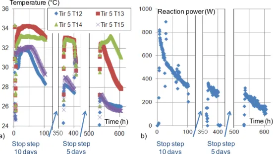
Two steps of long-time stop (five and ten days) were introduced in the third hydration experiment. For both stop steps, the reactor temperature dropped naturally down to ambient temperature (20°C). These stops are similar to the operation of a seasonal storage system during offseason periods (fall and spring) when storage can be started and stopped several times for a few days each time.
Figure 8 presents local temperatures and thermal power evolutions. Figure 8a shows that, after each stop, the reaction power rises very quickly up to the same value as before the stop. The temperature behavior gauged by four thermocouples located in the middle of module 5 at different heights in the salt bed was also similar (Figure 8b). The temperature profile in the bed does not change before and after each stop step.
Note that the decrease in the salt temperature and reaction power during hydration is not caused by the stop steps, but is due to the classic decrease in such solid/gas reaction kinetics that occurs with reaction progress (see §4.1.1). Moreover, Figure 7 shows that the reaction power of this third discontinuous hydration was similar to that in other continuous hydrations.
Therefore, long-term stop steps don’t have any significant effect on the global performance of the thermochemical reactor.
-1600 -1200 -800 -400 0 400 800 0 0,1 0,2 0,3 0,4 0,5 0,6 0,7 0,8 0,9 1 Reaction power (W) Advancement
Target
Hy dration Dehy dration 1st 2nd 3rd 4th 6th 7th Cycles16
Figure 8 : Intermittent operation of the prototype including two long time stops (third hydration) a) Temperature of the salt bed (module 5), at different heights (1.8, 3.3, 4.9 and 6.7 cm),
b) Thermal power released by this hydration.
4.2.
System control
So far, this paper has fully demonstrated the feasibility of a thermochemical storage system and analyzed its working mode. In addition, it is important to control the thermal power and temperature output supplied by the storage in order to meet user demand. Thus, this portion investigates the influence of two parameters that could allow control of such a thermochemical storage system: the moist air flow rate and the equilibrium drop.
4.2.1. Influence of the moist air flow rate
This experiment (cycle 7) involved four steps carried out at different mass flow rates of moist air: 313, 250, 200 and 150 m3/h, and a constant high equilibrium drop. Each step lasted seven hours, and the whole experiment ran from advancement X=0.55 to 0.27 in the dehydration phase, and from X=0.3 to 0.43 in the hydration phase.
Figure 9a and Figure 9b, present the reaction thermal power as a function of the moist air mass flow rate for hydration and dehydration. Each point is an averaged value calculated over the seven hour step at a fixed flow rate. These figures demonstrate the quite linear relationship between the thermal power of the reaction and the moist air flow rate for both reactions. As discussed in [30], this linear correlation also indicates that mass transfer in the porous reactive bed is the limiting phenomenon of the reaction in the prototype under study.
Thus, in this case, the thermal power consumed/supplied by the thermochemical reactor can be easily managed by controlling the flow of moist air through the reactive bed.
Temperature ( C) Time (h) Stop step 10 days Stop step 5 days Reaction power (W) Time (h) Stop step 10 days Stop step 5 days a) b)
17
Figure 9 : Reaction thermal power as a function of the mass flow rate of moist air. a) hydration, b) dehydration (Cycle 7).
4.2.2. Influence of the equilibrium drop
The fifth cycle (hydration/dehydration) was carried out by alternating periods with high and low equilibrium drops (see Table 3). All other parameters were identical to previous cycles. Each period was long enough to reach a quasi-stationary state. Each one lasted at least 20 h, and the whole hydration / dehydration cycle lasted respectively 160 h and 350 h.
Figure 10 presents the thermal power as a function of advancement over this unique cycle. This figure exhibits a strong change in the power according to the equilibrium drop. In the case of dehydration, at mid-hydration (X=0.5) the thermal power changed from -600 W to -180 W for an equilibrium drop which corresponded, respectively, to air input temperatures of 80°C and 60°C. The lower temperature leads to a very small reaction affinity (Table 3), which explains the weak power released by the reactor in this case.
During hydration, at X=0.5, the power changed from 500 to 250 W going from a high to a low equilibrium drop.
Notice that in the case of hydration the experimental protocol is slightly different as the high and low equilibrium drops correspond to two different water partial pressures, respectively 1000 Pa and 700 Pa (see Figure 4). Consequently, the input mass flow rate of water vapor also diminishes and results in a decrease in the reaction power. The effects of the equilibrium drop and water partial pressure overlap.
However, it is possible to quantify the portion resulting from each effect. Let’s recall that in the previous paragraph Figure 9 correlates the reaction power and moist air mass flow rate, and allows the correlation between this power and the water vapor mass flow rate (linear relationship) to be deduced. Therefore, the power change at X=0.5 (figure 10) due to the decrease in the water mass flow rate can be evaluated as 148 W (at X=0.5) and, consequently, the change in the equilibrium deviation leads to a decrease of 102 W.
200 400 600 800 1000 160 210 260 310 360 -800 -700 -600 -500 -400 -300 140 190 240 290 Reaction power (W)
Mass flow rate (kg/h) Reaction power (W)
Mass flow rate (kg/h)
Hydration
Dehydration
18 Figure 10: Thermal power ( ) released or consumed by the reaction as a function of the
advancement for a cycle alternating high and low equilibrium drops.
Thus, the equilibrium drop has a strong influence: a rather slight variation in the operating conditions (of 300 Pa in hydration, of 20°C in dehydration, see Table 3) can change the reactor’s thermal power to a significant extent. It is therefore essential to control this parameter by acting on the humidity or temperature of the inlet moist air (see Figure 4). Selecting a high humidity moist air source for the hydration step and using a solar collector able to efficiently heat this moist air flow in the dehydration step are both key ways to control the input/output thermal power of the storage reactor. Moreover, this strong sensitivity of reactor performance to the equilibrium drop confirms the need for accurate models, as developed in a previous paper [30], describing the particular workings of the thermochemical reactor.
Finally, this study demonstrates that managing the equilibrium drop and the moist air flow is an efficient way to control the thermal power supplied by the thermochemical system.
4.2.3. Output air temperature
Classical thermochemical systems operating with pure vapor are generally limited by conductive heat transfer within the porous reactive bed [34,37,30]. Thus, they usually operate in an isobaric manner and their working conditions (temperature, T, and vapor pressure pv) can be plotted on a horizontal isobaric line in a Clausius-Clapeyron diagram.
Conversely, for a system working with moist air, the conditions at the input (Ti, pvi) and output (Tj, pvj) of the reactive bed are not located on an isobaric line (i.e. the water pressure evolves as the moist air flows across the reactive bed). Assuming stationary operation and neglecting heat losses, a simplified linear relationship between the input-output temperature lift Tj–Ti, and the outlet partial pressure of moist air, pvj, (or the outlet specific humidity wj) has been
-1200 -1000 - 800 -600 -400 -200 0 200 400 600 0,2 0,3 0,4 0,5 0,6 0,7 0,8 Advancement Reaction power (W) Equilibrium deviation
High . hy d ra ti o n Low d e h y d ra ti o n High Low
19 developed by several authors [30,40,41]. This linear relationship depends only on the input humidity conditions (wi or pvi) and characteristics of the solid/gas reactive pair.
(8) T’ is the temperature in C, and cma and cmv are, respectively, the heat capacity of the dry air
and the vapor.
An example of this linear relationship is plotted as pvj vs. Tj in Figure 11 for the seventh hydration and dehydration, and for input operating conditions Ti, pvi given in
Table 4 (high equilibrium drop).
Thus, for these input conditions (Ti and pvi or wi), the output moist air conditions Tj and pvj
are located on this 'temperature lift' line defined by Equation 8.
Moreover, the reactive bed conditions Tj, pvj are obviously limited by the thermodynamic equilibrium conditions defined by Equation 2. Therefore, during hydration, the maximum output temperature Tj is the crosspoint of this temperature lift line (equation 8) and the equilibrium line (equation 2), both plotted in Figure 11a. Symmetrically, this crosspoint is the minimum output temperature during dehydration (Figure 11b).
Thus, for the 7th cycle, Figure 11a shows that the maximal moist air temperature at the reactor output during hydration is 35.4°C. For input conditions corresponding to the low equilibrium drop (not plotted), this maximum output temperature would be 31.8 °C.
Figure 11 also presents the experimental output temperature and pressure for each portion of the seventh cycle carried out at different mass flow rates during hydration and dehydration as described in part 4.2.2. These figures clearly show that there is no significant variation in the output moist air conditions over the experimental range of flow rates (from 150 to 300 m3/h).
The slight displacement of the output point is due to the reaction’s progress and the corresponding decrease in the reaction rate, as presented for hydration 3 in Figure 7. At the end of the reaction this output point will move quickly up to the input point.
Figure 11 : Average input and output air conditions (pv and T) for the 7th cycle.
a) Hydration b) Dehydration
Symbols refer to different moist air flow rates. Blue line: temperature lift line (equation 8). Red dotted line: thermodynamic equilibrium (equation 2).
200 400 600 800 1000 24 28 32 36 40 2400 2600 2800 3000 3200 3400 50 55 60 65 70 75 80 a) b) Temperature ( C) pv(Pa) pv(Pa) 300 m3/h 250 m3/h 200 m3/h 150 m3/h Input Output Eq S/G
Temperature lift line
Temperature ( C)
20 Thus, this experiment and analysis clearly demonstrate that controlling the air flow rate is not a relevant way to control the temperature at the reactor output.
5.
Conclusion
This work investigates a thermochemical system dedicated to high density and long term (seasonal) storage purposes. This paper focuses on an innovative working mode with moist air. It leads to a simpler reactor design and a lower cost than the usual pure vapor working mode but the management of this original system has to be thoroughly investigated. Experiments were carried out on a prototype at a significant scale. They allow promising conclusions to be drawn regarding the feasibility, working mode and performance of such a storage process.
Thanks to previous works about reactive materials and solid/gas reactor modeling, a large prototype (400 kg of hydrated salt, 105 kWh storage capacity, and Der = 203 kWh/m3) was designed, built and experimented with for several hydration/dehydration cycles. The experiments showed a decrease in the reaction rate for the very first cycles, then the reactor kinetics seemed to stabilize from the sixth cycle on. The specific thermal power released by the reactor during hydration was higher than the target range defined for space heating in typical houses in the French climate. An intermittent operating mode combining reactive and non-reactive steps, such as can occur during offseason periods, did not affect the temperature profile within the reactive bed nor the thermal power output released by the storage system.
Furthermore, ways to control this storage system in order to meet user demand were investigated. This control involves, on the one hand, the thermal power released by the reactor in the destorage step, and on the other hand the moist air temperature at the reactor outlet. Two important parameters were investigated: the equilibrium drop (i.e. the difference between moist air input conditions and thermodynamic equilibrium of the reaction) and the mass flow rate of the moist air. Both have a strong influence on the reactor kinetics and therefore on the reactor thermal power. A direct and quite linear relationship between the moist air mass flow rate and the reactor thermal power output has been highlighted. Conversely, the output moist air temperature is not changed by the air flow rate (in the range tested) but it depends on the input conditions of the moist air flow (temperature and humidity).
Therefore, the mass flow rate is a simple control parameter but it can only regulate the reaction power supplied by the thermochemical reactor. On the other hand, controlling the moist air conditions at the reactor inlet is relevant to regulating both reactor features: its thermal power and the moist air outlet temperature.
Thus, this study clearly demonstrates the feasibility of a long-term storage system involving a thermochemical process operating with moist air, and has enabled the identification of efficient and simple ways to control the thermal power output in order to meet user demand.
21
Acknowledgement
We thank the French National Research Agency (Agence Nationale de la Recherche) for their financial support for the ESSI project (ANR-08-STOCK-E-04) and the project partner INES developing the aeraulic bench.
References:
[1] International Energy Agency. World energy statistics. 2011.
[2] Pinel P, Cruickshank CA, Beausoleil-Morrison I, Wills A. A review of available
methods for seasonal storage of solar thermal energy in residential applications.
Renewable and Sustainable Energy Reviews 2011;15:3341
–59.
[3]
N’Tsoukpoe KE, Liu H, Le Pierrès N, Luo L. A review on long-term sorption solar
energy storage. Renewable and Sustainable Energy Reviews 2009;13:2385
–96.
[4] Hadorn J-C. Advanced storage concepts for active solar energy
—IEA SHC Task 32
2003-2007. In proceeding of Eurosun, Lisbon, Portugal: 2008.
[5] Stitou D, Mazet N, Bonnissel M. Performance of a high temperature hydrate solid/gas
sorption heat pump used as topping cycle for cascaded sorption chillers. Energy
2004;29:267
–85.
[6] Stitou D, Mazet N, Mauran S. Experimental investigation of a solid/gas thermochemical
storage process for solar air-conditioning. Energy 2012;41:261
–70.
[7] Mauran S, Lahmidi H, Goetz V. Solar heating and cooling by a thermochemical
process. First experiments of a prototype storing 60 kW h by a solid/gas reaction. Solar
Energy 2008;82:623
–36.
[8] Zondag H, Kikkert B, Smeding S, Boer R de, Bakker M. Prototype thermochemical heat
storage with open reactor system. Applied Energy 2013;109:360
–5.
[9] Weber R, Kerskes H, Drück H, Müller-Steinhagen H. New Solar Thermal Storage
Concept
– Combined Hot Water and Sorption Store –. Proceeding of EuroSun, Gratz,
Austria: 2010.
[10] Bales C, Nordlander S. TCA Evaluation - Lab Measurments, Modelling and System
Simulations. Högskolan Dalarna, Borlänge: 2005.
[11] Le Pierrès N, Liu H, Lingai L. CaCl2/H2O absorption seasonal storage of solar heat. In
Proceeding of the International Conference for Sustainable Energy Storage, Belfast,
Ulster: 2011.
[12] Jaehning D, Hausner R, Wagner W, Isaksson C. Thermo-chemical storage for solar
space heating in single-family house. In: Proceeding of Ecostock, New Jersey: 2006.
[13] Gartler G, Jähnig D, Purkarthofer G, Wagner W. Development of a high energy density
sorption storage system. In Proceedings of the EuroSun Conference, Freiburg, Germany,
2004.
[14] Bales C. Chemical and sorption heat storage, DTU Lyngby: 2006.
[15] Marias F, Tanguy G, Wynttenbach J, Rouge S, Papillon P. Thermochemical storage:
first results of pilot storage with moist air. In: Proceeding of ISES, Kassel, Germany:
2011.
[16] Iammak K, Wongsuwan W, Kiatsiriroj T. Investigation of modular chemical energy
storage performance. In proceeding of the joint international conference on sustainable
energy and environment (SEE), 2004.
[17] De Boer R, Haije W, Veldhuis J, Smeding S. Solid sorption cooling with integrated
storage: the SWEAT prototype. 3rd international heat powered cycles conference
—
HPC, Larnaca, Cyprus: 2004.
22
[18] Hongois S, Kuznik F, Stevens P, Roux J-J. Development and characterisation of a new
MgSO4−zeolite composite for long-term thermal energy storage. Solar Energy Materials
and Solar Cells 2011;95:1831
–7.
[19] Bales C. Laboratory Tests of Chemical Reactions and Prototype Sorption Storage Units.
A Report of IEA Solar Heating and Cooling programme - Task 32 Advanced storage
concepts for solar and low energy buildings. 2008.
[20] Xu J, Wang RZ, Li Y. A review of available technologies for seasonal thermal energy
storage. Solar Energy 2013.
[21] Yu N, Wang RZ, Wang LW. Sorption thermal storage for solar energy. Progress in
Energy and Combustion Science 2013;39:489
–514.
[22] Michel B, Mazet N, Mauran S, Stitou D, Xu J. Thermochemical process for seasonal
storage of solar energy: Characterization and modeling of a high density reactive bed.
Energy 2012;47:553
–63.
[23] Hauer A, Lävemann E. Open absorption systems for air conditionning and themal
energy storage, Thermal energy storage for sustainable energy consumption, Netherland:
Springer; 2007, p. 429:444.
[24] Bertsch F, Mette B, Asenbeck S, Kerskes H, Müller-Steinhagen H. Low temperature
chemical heat storage
–an investigation of hydration reactions. In: Proceeding of
Effstock, New Jersey: 2009.
[25] Abedin AH, Rosen MA. Assessment of a closed thermochemical energy storage using
energy and exergy methods. Applied Energy 2012;93:18
–23.
[26] Tanguy G, Papillon P, Paulus C. Seasonal storage coupled to solar combisystem:
dynamic simulations for process dimensioning. In Proceeding of EuroSun, Gratz,
Austria: 2010.
[27] Heimrath R, Haller M. Project Report A2 of Subtask A, the Reference Heating System,
the Template Solar System. A Report of the IEA-SHC Task32 2007.
[28] Mauran S, Lahmidi H, Goetz V. 3rd Intermediate Report, European project no
NNE5-2000-00385. 2002.
[29] Lide DR. CRC Handbook of Chemistry and Physics. CRC Press; 2012.
[30]
Michel B. Procédé thermochimique pour le stockage intersaisonnier de l’énergie solaire:
modélisation multi-
échelles et expérimentation d’un prototype sous air humide. PhD
Thesis, Université Perpignan Via Domitia, 2012.
[31] Zondag HA, Van Essen M, Bleijendaal L, Cot J, Schuitema R, Planje W, et al.
Comparison of reactor concepts for thermochemical storage of solar heat. In: Proceeding
of IRES, 2008.
[32] Zondag H., Van Essen V., Schuitema R, Bleijendaal LP., Van Helden WG., Bakker M.
Engineering assessment of reactor designs for thermochemical storage of solar heat. In
proceeding of Effstock, Thermal Energy Storage for Energy Efficiency and
Sustainability, Stockholm, Sweden: 2009.
[33] Le Pierrès N, Mazet N, Stitou D. Experimental results of a solar powered cooling
system at low temperature. International Journal of Refrigeration 2007;30:1050
–8.
[34]
Mauran S, Prades P, L’Haridon F. Heat and mass transfer in consolidated reacting beds
for thermochemical systems. Heat Recovery Systems and CHP 1993;13:315
–9.
[35] Lu H-B, Mazet N, Coudevylle O, Mauran S. Comparison of a general model with a
simplified approach for the transformation of solid-gas media used in chemical heat
transformers. Chemical Engineering Science 1997;52:311
–27.
[36] Ashrae Handbook: Fundamentals. American Society of Heating, Refrigerating and
Air-Conditioning Engineers, Incorporated; 2009.
[37] Lu H-B, Mazet N, Spinner B. Modelling of gas-solid reaction
—Coupling of heat and
mass transfer with chemical reaction. Chemical Engineering Science 1996;51:3829
–45.
23
![Figure 1: Energy densities of various sorption storage prototypes as function of the energy density of the reactive materials implemented in the prototype: TCA (LiBr/H2O, [10]), HYDES and MODSTORE (Silica gel/H2O, [12,13]), SPF (Zeolithe](https://thumb-eu.123doks.com/thumbv2/123doknet/14452258.518837/4.892.144.749.116.387/densities-sorption-prototypes-materials-implemented-prototype-modstore-zeolithe.webp)