ComTouch : a vibrotactile mobile communication device
Texte intégral
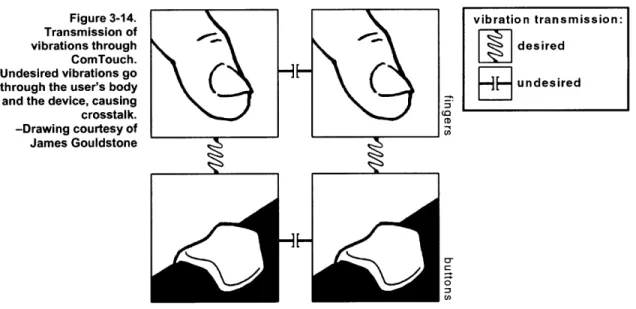
Figure


Documents relatifs
Using pronouns to refer back to entities already intro duced in the text. After Ma ry prop osed to John, they found a preacher and got
Finally, the nightmare continued with a third code blue announcement approximately 3 minutes later, back at the original medical ward.. Some min- utes later, a frantic
Jusqu'a ia mise en place des r^seaux de commutation de circuits X21 en 198V et du reseau public de transmission de donnees nar Daauet X25 en 1990 en phase.. utilisateurs du fait de
the first aspect , if user communication devices of a possible group of different possible groups among the user commu nication devices of the neighbor user communication device
• Acte au cours duquel un individu « « émetteur émetteur » » traduit un fait, un concept, un sentiment en un message message qu’il adresse par le canal
[r]
• La convocation symbolique de la parole dans la communication Olivier, AIM (Université Paris-Sorbonne, FRANCE) Jacqueline, CHERVIN (Université Paris-Sorbonne, FRANCE)
Ce dernier axe s’efforcera d’explorer la dimension symbolique ou métaphorique qui innerve certains discours communicationnels, notamment ceux qui servent à décrire une
