A Computer-Aided Design Methodology for Low
Power Sequential Logic Circuits
by
Jos Carlos Alves Pereira Monteiro
Engenheiro Electrot6cnico e de Computadores,
Instituto Superior T6cnico, Lisboa, Portugal (1989)
Mestre em Engenharia Electrot6cnica e de Computadores,
Instituto Superior T6cnico, Lisboa, Portugal (1993)
Submitted to the
Department of Electrical Engineering and Computer Science
in partial fulfillment of the requirements for the degree of
Doctor of Philosophy
at the
MASSACHUSETTS INSTITUTE OF TECHNOLOGY
May 1996
@ Massachusetts Institute of Technology 1996. All rights reserved.
tSSAkC.jUSETS iNSTILTE OF TECHNOLOGYJUL
1
6
1996
LIBRARIES Author . ... ..--- ----'•Department of Electrical Engineering and Computer Science
.
"
..
May 21, 1996
Certified
Srinivas Devadas
Associate Professor •f Electrical Engineering and Computer Science
Thesis Supervisor
Accepted by
Frederi R. Moge••er, Professor of Electrical Engineering
C airman, Deprtment Committee on. Graduate Students
A Computer-Aided Design Methodology for Low Power
Sequential Logic Circuits
by
Jose Carlos Alves Pereira Monteiro
Submitted to the
Department of Electrical Engineering and Computer Science
on May 21, 1996, in partial fulfillment of the requirements for the degree of Doctor of Philosophy
Abstract
Rapid increases in chip complexity, increasingly faster clocks, and the proliferation of portable devices have combined to make power dissipation an important design parameter. The power consumption of a digital system determines its heat dissipation as well as battery life. For some systems, power has become the most critical design constraint.
In this thesis we develop a methodology for low power design. We first present techniques for estimating the average power dissipation of a logic circuit. At the logic level, power dissipation is directly related to switching activity. We describe a symbolic simulation method to accurately and efficiently compute the switching activity in logic circuits. This method is extended to handle sequential logic circuits, namely by modeling correlation in time and by calculating the probabilities of present state
lines.
In the second part of this thesis we develop methods for the reduction of switching activity in logic circuits. We present a retiming method for low power. Registers are re-positioned such that the overall glitching in the circuit is minimized. We then propose a powerful optimization method that is based on selectively precomputing the output logic values of a circuit one clock cycle before they are required, and using the precomputed values to reduce internal switching activity in the succeeding clock cycle. Finally we describe a scheduling method that maximizes the inactivity period of the modules in a circuit.
Keywords-- low power design, power estimation, symbolic simulation, precomputa-tion, retiming, power management, scheduling.
Thesis Supervisor: Srinivas Devadas
Acknowledgments
First and foremost I am deeply grateful to my thesis advisor, Prof. Srinivas Devadas, for all the input and guidance he gave me throughout my doctoral program at MIT. His perspective, insight and clarity of thought are a continual source of inspiration. More than an advisor, I am proud to say he has been a good friend.
I would like to thank Mazhar Alidina for his initial work on precomputation, for the friendship and all the interesting conversations, both technical and philosophical. Thanks to Mike Chou, my officemate, for the friendship and help with the RN mathematics.
Special thanks go to Luis Miguel Silveira for all the support and help, and for giving me the incentive to come to MIT for my doctoral studies. I would also like to thank Cristina Lopes for all the encouragement she has always given me.
I am also appreciative of all the exceptional people on the 8th floor who have made it an excellent place to work. Namely thanks to Robert Armstrong, Mattan Kamon, Stan Liao, Ignacio McQuirk, Keith Nabors, Amelia Shen, Khalid Rahmat and Ricardo Telichevesky for their friendship and help.
Other people also contributed to make my stay in the USA such a great experience. Thanks to Jdlia Allen, Miguel and Ines Castro, Jorge Gongalves, Gail Payne, Nuno and Manuela Vasconcelos.
I owe much to my parents Ant6nio and Conceigio Monteiro and my sister Emrlia, who have always been there to support and encourage me.
Finally, very special thanks to Tila, for all her love, encouragement and patience. She *will* be seeing a lot more of me now!
This thesis work was carried out at the Research Laboratory of Electronics of the Massachusetts Institute of Technology. Part of the work on precomputation (Chapter 7) was done in a Summer job at Mitsubishi Electric Research Laboratories Inc, Sunnyvale, California. Part of the work on scheduling (Chapter 8) was done in a Summer job at C&C Research Labs, NEC USA, New Jersey.
8
This research was sponsored in part by the portuguese Junta Nacional de
Investiga-9io Cientifica e Tecnol6gica under project PRAXIS; in part by the Advanced Research
Projects Agency under contract number DABT63-94-C-0053; in part by an NSF Young Investigator Award with matching funds from Mitsubishi. Their financial support for this work is gratefully acknowledged.
About the Author
Jose Carlos Alves Pereira Monteiro was born on June 1,
1966, in Lisbon, Portugal. He received his Engineering and Masters degrees in Electrical Engineering and Computer Science, both from Instituto Superior T6cnico, Lisbon, in July 1989 and January 1993, respectively. The Masters thesis was entitled Finite State Machine Encoding in Logic Synthesis. His research interests include power analysis at different levels of abstraction, optimization for low power, and logic and high-level synthesis.
Jos6 was a recipient of the Fulbright Scholarship (September 1992). He received the 1995 Best Paper Award in the IEEE Transactions on VLSI Systems for his work on power estimation of sequential circuits. Jos6 is a member of the Institute of Electrical and Electronics Engineers (IEEE).
Recent Publications
J. Monteiro, S. Devadas. Techniques for Power Estimation and Optimization at the Logic Level: a Survey. Journal of VLSI Signal Processing, June 1996. To be published.
J. Monteiro, S. Devadas, and A. Ghosh. Retiming Sequential Circuits for Low Power. International Journal of High Speed Electronics and Systems, 7(2), June 1996. To be published.
J. Monteiro, S. Devadas, P. Ashar, and A. Mauskar. Scheduling Techniques to Enable Power Management. In Proceedings of the 3 3rd Design Automation Conference, June 96. To be published.
C-Y. Tsui, J. Monteiro, M. Pedram, S. Devadas, A. Despain, and B. Lin. Power Estimation for Sequential Logic Circuits. IEEE Transactions on VLSI Systems, 3(3):404-416, September 1995.
Contents
Abstract 3
Acknowledgments 7
About the Author 9
1 Introduction 17
1.1 Power as a Design Constraint ... ... 20
1.2 Organization of this Thesis ... 21
2 Power Estimation 23 2.1 Power Dissipation Model ... 24
2.2 Switching Activity Estimation ... ... 26
2.2.1 Simulation-Based Techniques . ... 26
2.2.2 Issues in Probabilistic Estimation Techniques ... 28
2.2.3 Probabilistic Techniques ... .. 32
2.3 Summary ... 35
3 A Power Estimation Method for Combinational Circuits 37 3.1 Symbolic Simulation ... 38
3.2 Transparent Latches ... 42
3.3 Modeling Inertial Delay ... 44 3.4 Power Estimation Results ...
3.5 Sum m ary ... .. .. .. .. ... .. . . .. .. ... .. .. .. 4 Power Estimation for Sequential Circuits
4.1 Pipelines . . . .
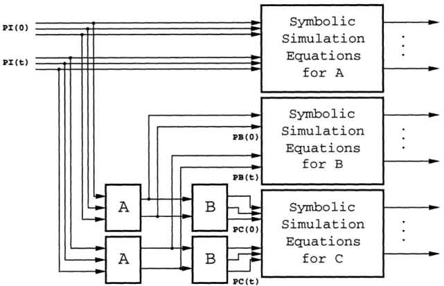
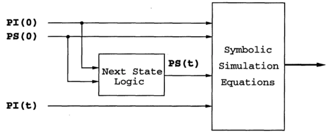
4.2 Finite State Machines: Exact Method . . . . 4.2.1 Modeling Temporal Correlation . . . . . ...
4.2.2 State Probability Computation . . . . 4.2.3 Power Estimation given State Probabilities . . . . 4.3 Finite State Machines: Approximate Method . . . . 4.3.1 Basis for the Approximation . . . . 4.3.2 Computing Present State Line Probabilities . . . . 4.3.3 Picard-Peano Method . . . . 4.3.4 Newton-Raphson Method . . . . 4.3.5 Improving Accuracy using m-Expanded Networks . . . . 4.3.6 Improving Accuracy using k-Unrolled Networks ... 4.3.7 Redundant State Lines ...
4.4 Results on Sequential Power Estimation Techniques . . . . 4.5 Modeling Correlation of Input Sequences . . . . 4.5.1 Completely- and Incompletely-Specified Input Sequences . 4.5.2 Assembly Programs ...
4.5.3 Experimental Results . . . . 4.6 Sum m ary ... .. .. .. .. ... .. .. .. .. ... .. .. ..
5 Optimization Techniques for Low Power Circuits
5.1 Power Optimization by Transistor Sizing . . . . 5.2 Combinational Logic Level Optimization . . . .
5.2.1 Path Balancing ... 5.2.2 Don't-care Optimization . . . . 5.2.3 Logic Factorization ... 5.2.4 Technology Mapping ... CONTENTS 99 100 102 103 104 105 106
CONTENTS
5.3 Sequential Optimization ... 108
5.3.1 State Encoding ... ... 108
5.3.2 Encoding in the Datapath ... 109
5.3.3 Gated Clocks ... 110
5.4 Summary ... ... . . . . 111
6 Retiming for Low Power 113 6.1 Review of Retiming . ... . ... ... 115
6.1.1 Basic Concepts ... 115
6.1.2 Applications of Retiming ... .. 117
6.2 Retiming for Low Power ... 118
6.2.1 Cost Function ... 119
6.2.2 Verifying a Given Clock Period ... . . . . 121
6.2.3 Retiming Constraints ... .... 121
6.2.4 Executing the Retiming ... ... 122
6.3 Experimental Results ... 124
6.4 Conclusions and Ongoing Work ... 126
7 Precomputation 129 7.1 Subset Input Disabling Precomputation . ... 130
7.1.1 Subset Input Disabling Precomputation Architecture ... 131
7.1.2 An Example ... 132
7.1.3 Synthesis of Precomputation Logic ... ... 134
7.1.4 Multiple-Output Functions . . . 139
7.1.5 Examples of Precomputation Applied to some Datapath Modules 143 7.1.6 Multiple Cycle Precomputation . ... 146
7.1.7 Experimental Results for the Subset Input Disabling Architecture 149 7.2 Complete Input Disabling Precomputation . ... 152
7.2.1 Complete Input Disabling Precomputation Architecture ... 152
CONTENTS
7.2.3 Synthesis of Precomputation Logic . ... 155
7.2.4 Simplifying the Original Combinational Logic Block ... 159
7.2.5 Multiple-Output Functions . ... . 160
7.2.6 Experimental Results for the Complete Input Disabling Archi-tecture . . . 160
7.3 Combinational Precomputation ... ... 162
7.3.1 Combinational Logic Precomputation . . ... ... 162
7.3.2 Precomputation at the Inputs . ... .. ... 164
7.3.3 Precomputation for Arbitrary Sub-Circuits in a Circuit ... 164
7.3.4 Experimental Results for the Combinational Precomputation Ar-chitecture . . . .. . . . .. . 168
7.4 Multiplexor-Based Precomputation . . . ... . . . 169
7.5 Conclusions and Ongoing Work ... .. 171
8 Scheduling Techniques to Enable Power Management 173 8.1 Scheduling and the Ability for Power Management ... . 174
8.2 Mutually Exclusive Operations ... . . . .. ... .... 177
8.3 Scheduling Algorithm ... 179
8.4 Example: Dealer ... ... 181
8.4.1 Multiplexor Selection ... ... 183
8.4.2 Controller Generation ... .... 186
8.5 Techniques to Improve Power Management . ... 187
8.5.1 Multiplexor Reordering ... ... 187
8.5.2 Pipelining ... .. ... .... . 189
8.6 Experimental Results ... 190
8.7 Conclusions and Ongoing Work . ... .. 192
9 Conclusion 193 9.1 Power Estimation ... 193
A Computer-Aided Methodology for
Low Power Sequential Logic Circuits
Chapter 1
Introduction
Digital integrated circuits are ubiquitous in systems that require computation. During the years of their inception, the use of integrated circuits was confined to traditional electronic systems such as computers, high-fidelity sound systems, and communication systems. Today not only do computer and communication systems play an increasingly important role, but also the use of integrated systems is much more widespread, from controllers used in washing machines to the automobile industry. As a result, digital circuits are becoming more application specific.
The shrinking of device sizes due to the improvement of fabrication technology has increased dramatically the number of transistors available for use in a single chip. Functions that were performed by several chips can now be done within a single chip, reducing the physical size of the electronic component of the system. The larger capacity of the chips is also being used to extend the functionality of the systems. The overall consequence is a substantial increase in complexity of the integrated circuits.
In order to handle the ever increasing complexity, computer-aided design tools have been developed. These tools have to be general enough to produce good solutions for the broad range of applications for which integrated circuits are being designed.
The first generation of computer-aided design tools dealt with automatically gen-erating the layout masks from the description of the circuit at the logic level. Then
INTRODUCTION
logic synthesis tools were introduced to obtain optimized logic circuits from some input/output specification. More recently, tools that can do system-level optimization given a Register-Transfer Level (RTL) description have been proposed. The trend towards moving the circuit specification to higher level descriptions continues with research being conducted at the behavioral synthesis level. At this level, the circuit description is akin to an algorithmic description and the synthesis tool decides which registers and functional units to use and assigns each operation to one of these units
on a given clock cycle.
A complete synthesis system is presented in Figure 1-1. Each synthesis tool trans-lates a description of the circuit into an optimized description at a lower level. At every description level, area, timing and power dissipation estimates can be obtained and used to drive the synthesis tool such that the design's constraints are met. If at some level any of these constraints is violated, the designer needs to go back one or more description levels and redo the synthesis with different parameters, perhaps relaxing some constraint.
As shown in Figure 1-1, the logic synthesis process is usually split into two different phases. First logic optimization is performed on a Boolean description of the circuit. Technology mapping is then performed on this optimized circuit - this consists of translating the generic Boolean description to logic gates existing in the chosen library. This library is specific to the fabrication process that is going to be used and has precise layout, area and timing information for each gate. Design estimates at this level are therefore more precise than at higher levels.
Also shown in Figure 1-1 is the automatic test generator module [ABF90]. At the logic level, this tool generates a set of input patterns that attempts to identify possible circuit malfunctions after fabrication. These input patterns can then be used to test the functionality of the fabricated chips and should be small in number to minimize the test time. Although automatic test generation is seemingly independent from the synthesis process, testability-aware synthesis algorithms can dramatically improve the performance of the test generator.
INTRODUCTION
INTRODUCTION
1.1 Power as a Design Constraint
Traditionally the constraints in the design of an integrated circuit have been timing and area [BHMSV84, BRSVW87, BHJ+87, ADN91]. When designing a circuit, there is usually a performance goal which translates to a maximum duration that any logic signal can take to stabilize after the inputs have stabilized. The second concern is that the circuit should take up as little area as possible since die area has a direct correspondence to cost. Further, this is not a linear relationship as the larger the circuit the more probable it is that there is a fabrication process error in a circuit, lowering circuit yield [Wal87, Chapter 2].
However, the importance of low-power dissipative digital circuits is rapidly in-creasing. For many consumer electronic applications low average power dissipation is desirable and for certain special applications low power dissipation is of critical importance. For personal communication applications like hand-held mobile telephones, low power dissipation may be the tightest constraint in the design. The battery lifetime may be the decisive factor in the success of the product.
More generally, with the increasing scale of integration and faster clock frequencies, we believe that power dissipation will assume greater importance, especially in multi-chip modules where heat dissipation is one of the biggest problems. Even today, power dissipation is already a significant problem for some circuits. General purpose processors such as the Intel Pentiuni and DEC AlphaTM consume 16W and 30W, respectively. Higher temperatures can affect the circuit's reliability and reduce the lifetime of the system [Chr94]. In order to dissipate the heat that is generated, special packaging and cooling systems have to be used, leading to higher costs.
Optimization for low power can be applied at many different levels of the design hierarchy. The average power dissipation of a circuit, like its area or speed, may be significantly improved by changing the architecture of the circuit [CSB92]. Algorithmic and architectural transformations can trade-off throughput, circuit area, and power dissipation. Furthermore, scaling technology parameters such as supply and threshold
1.2 ORGANIZATION OF THIS THESIS
voltages can substantially reduce power dissipation. But once these architectural or technological improvements have been made, it is the switching of the logic that will ultimately determine its power dissipation.
The focus of this thesis is a methodology for the optimization of digital circuits for low power at the logic level. The techniques developed are independent of the power reduction techniques applied at higher levels and can be used after system-level decisions are made and high-level transformations applied.
To effectively optimize designs for low power, however, accurate power estimation methods must be developed and used. Power dissipation is generally considered to be more difficult to compute than the estimation of other circuit parameters, like area and delay. The main reason for this difficulty is that power dissipation is dependent on the activity of the circuit. Therefore, in the first part of this thesis we focus on the power estimation problem.
1.2 Organization of this Thesis
This thesis is organized in two main parts. The first part addresses the problem of estimating the average power dissipation of a circuit given its description at the logic level. We start by describing in Chapter 2 the issues involved in computing the power dissipation of digital circuit. We show that power is directly related to the switching activity of the signals in the circuit. We provide a critique of existing power estimation techniques, namely by pointing out how each technique addresses the issues previously mentioned.
Chapter 3 presents our approach to power estimation for combinational logic circuits. We discuss the merits and drawbacks of our approach and provide comparisons with previous methods.
The power estimation techniques mentioned in Chapters 2 and 3 target combinational circuits. In general, digital integrated circuits are sequential, i.e., they contain memory elements. Chapter 4 describes the technique we have developed that extends the method
INTRODUCTION
of Chapter 3 to the sequential circuit case. However, this technique is general enough to be used with any other combinational power estimation method.
One other factor that needs to be taken into account in accurate power estimation is the temporal correlation of primary inputs. Also in Chapter 4, we show how to model this correlation and obtain an accurate power estimation by making use of a sequential power estimator.
The second part of the thesis is devoted to optimization methods for low power. Chapter 5 presents a survey of the most significant techniques that have been proposed thus far to reduce the power consumption of digital circuits at the logic level. The next three chapters present original work on sequential logic optimization for low power.
Chapter 6 describes a retiming technique for low power. The main observation is that the switching activity at the output of a register can be significantly less than that at the register's input. Any glitching in the input signal is filtered by the register. The technique we propose repositions the registers in the logic circuit such that the overall switching activity in the circuit is minimized.
In Chapter 7, a power management optimization technique is presented. The logic values at the output of a circuit are selectively precomputed one clock cycle before they are required, and these precomputed values are used to reduce internal switching activity in the succeeding clock cycle. For a large number of circuits, significant power reductions can be achieved by this data-dependent circuit power down.
We present another power management optimization technique in Chapter 8. Given a behavioral description of the system, we propose a scheduling algorithm that maximizes the potential for power management in the resulting circuit.
Finally, Chapter 9 concludes the thesis with a retrospective examination of what has been achieved in this thesis, and provides directions for future research.
Chapter 2
Power Estimation
For
power to be used as a design parameter, tools are needed that can efficiently estimate the power consumption of a given design. As in most engineering problems we have tradeoffs, in this case between the accuracy and run-time of the tool.Accurate power values can be obtained from circuit-level simulators such as SPICE [Qua89]. In practice, these simulators cannot be used in circuits with more than a few thousand transistors, so their applicability in logic design is very limited - they are essentially used to characterize simple logic cells.
A good compromise between accuracy and complexity is switch-level simulation. Simulation of entire chips can be done within reasonable amounts of CPU time [Tja89, SH89]. This property makes switch-level simulators very important power diagnosis tools. After layout and before fabrication these tools can be used to identify hot spots in the design, i.e., areas in the circuit where current densities or temperature may exceed the safety limits during normal operation.
At the logic level, a more simplified power dissipation model is used, leading to a faster power estimation process. Although detailed circuit behavior is not modeled, the estimation values can still be reasonably accurate. Obtaining fast power estimates is critical in order to allow a designer to compare different designs. Further, for the purpose of directing a designer or a synthesis tool for low power design, rather than
POWER ESTIMATION
an absolute measure of how much power a particular circuit consumes, an accurate relative power measure between two designs will suffice.
This observation is carried out further to justify power estimation schemes at higher abstraction levels. In [LR94] a power estimation technique at the register-transfer (RT) level is presented. Power coefficients are computed beforehand for datapath modules (such as adders, multipliers, etc) and stored in the module library database. The circuit described at the RT level is simulated for some input vectors and power values are calculated from the circuit activity and the module coefficients. In [Naj95] and [MMP95a] the focus is to derive implementation-independent measures of the signal activity in the circuit. Although with any of these techniques a very crude power figure is obtained, it may be sufficiently accurate in relative terms to allow the comparison between different circuit architectures.
In this thesis we focus on power estimation and optimization at the logic level. This level is perhaps where the best accuracy versus run-time tradeoff is reached. We first describe the power dissipation model that we use at the logic level in Section 2.1. We then present in Section 2.2 a survey of the most significant power estimation techniques at the logic level that have been previously proposed. Both simulation-based (Section 2.2.1) and probabilistic (Section 2.2.3) techniques are reviewed and the issues involved in each technique are discussed.
2.1 Power Dissipation Model
The sources of power dissipation in CMOS devices are summarized by the following expression [WE94, p. 236]:
P = 1-.C.VD.f N + Qsc-VDD'f'N + Ileak'VDD (2.1)
where P denotes the total power, VDD is the supply voltage, and f is the frequency of operation.
The first term in Equation 2.1 corresponds to the power involved in charging and discharging circuit nodes. C represents the node capacitances and N is the switching
2.1 POWER DISSIPATION MODEL
activity, i.e., the number of gate output transitions per clock cycle (also known as
transition density [Naj93]). -C V~2D is the energy involved in charging or discharging
a circuit node with capacitance C and f. N is the average number of times per second that the nodes switches.
The second term in Equation 2.1 represents the power dissipation due to current flowing directly from the supply to ground during the (hopefully small) period that the pull-up and pull-down networks of the CMOS gate are both conducting when the output switches. This current is often called short-circuit current. The factor Qsc represents the quantity of charge carried by the short-circuit current per transition.
The third term in Equation 2.1 is related to the static power dissipation due to
leakage current l,,eak. The transistor source and drain diffusions in a MOS device
form parasitic diodes with bulk regions. Reverse bias currents in these diodes dissipate power. Subthreshold transistor currents also dissipate power. I,eak accounts for both these small currents.
These three factors for power dissipation are often referred to as switching activity
power, short-circuit power and leakage current power respectively.
It has been shown [CSB92] that during normal operation of well designed CMOS circuits the switching activity power accounts for over 90% of the total power dis-sipation. Thus power optimization techniques at different levels of abstraction target minimal switching activity power. The model for power dissipation for a gate i in a logic circuit is simplified to:
1
Pi = .Ci"VD"f" Ni (2.2)
The supply voltage VDD and the clock frequency f are defined prior to logic design. The capacitive load C; that the gate is driving can be extracted from the circuit. This capacitance includes the source-drain capacitance of the gate itself, the input capacitances of the fanout gates and, if available, the wiring capacitance. Therefore the problem of logic level power estimation reduces to computing an accurate estimate of the average number of transitions Ni for each gate in the circuit. In the remainder
POWER ESTIMATION
of this chapter we present a review and critique of techniques for the computation of switching activity in logic circuits.
2.2 Switching Activity Estimation
The techniques we present in this section target average switching activity estimation. This is typically the value used to guide optimization methods for low power.
Some work has been done on identifying and computing conditions which lead to maximum power dissipation. In [DKW92] a technique is presented that implicitly determines the two input vector sequence that leads to maximum power dissipation in a combinational circuit. More recently, in [MPB+95] a method for computing the multiple vector cycle in a sequential circuit that dissipates maximum average power is described.
2.2.1 Simulation-Based Techniques
A straightforward approach to obtain an average transition count at every gate in the circuit is to use a logic or timing simulator and simulate the circuit for a sufficiently
large number of randomly generated input vectors. The main advantage of this approach
is that existing logic simulators can be used directly and issues such as glitching and internal signal correlation are automatically taken into account by the logic simulator. The most important aspect of simulation-based switching activity estimation is deciding how many input vectors to simulate in order to achieve a given accuracy level. A basic assumption is that under random inputs the power consumed by a circuit over a period of time T has a Normal distribution. Given a user-specified allowed percentage error f and confidence level a, the approach described in [BNYT93] uses the Central Limit Theorem [Pap91, pp. 214-221] to compute the number of input vectors with which to simulate the circuit with. Witha x 100% confidence,
_p
- P1 < erf-'(2) x s/ I , where p and s are the measured average and standard deviation of the power, P is the true average power dissipation, N the number of
2.2 SWITCHING ACTIVITY ESTIMATION
input vectors and erf- l() is the inverse error function [Pap91, p. 49] obtained from the Normal distribution. Since we require P < e, it follows that
p
NŽ (erf'(x p ) (2.3)
For a typical logic circuit and reasonable error and confidence levels, the numbers of vectors needed is usually small, making this approach very efficient.
A limitation of the technique presented in [BNYT93] is that it only guarantees accuracy for the average switching activity over all the gates. The switching activity values for individual gates (Ni in Equation 2.2) may have large errors and these values are important for many optimization techniques.
This method is augmented in [XN94] by allowing the user to specify the percentage error and confidence level for the switching activity of individual gates. Equation 2.3 is used for each node in the circuit, where instead of power, the average and standard deviation of the number of transitions in the node is the relevant parameter. The number of input vectors N is obtained as the minimum N that verifies Equation 2.3 for all the nodes.
The problem now is that gates which have a low switching probability, low-density
nodes, may require a very large number of input vectors in order for the estimation to
be within the percentage error specified by the user. The authors solve this problem by being less restrictive for these gates: an absolute error bound is used instead of the percentage error. The impact of possible larger errors for low-density nodes is minimized by the fact that these gates have the least effect on power dissipation and circuit reliability.
Other methods [HK95] try to compute a tighter bound on the number of input vectors to simulate. Instead of relying on normal distribution properties, the authors assume that the number of transitions at the output of a gate has a multinomial distribution. However, this method has to make a number of empirical approximations in order to obtain the number of input vectors.
POWER ESTIMATION
Simulation-based techniques can be very efficient for loose accuracy bounds. In-creasing the accuracy may require a prohibitively high number of simulation vectors. Using simulation-based methods in a synthesis scenario, where a circuit is being in-crementally modified and power estimates have to be obtained repeatedly for subsets of nodes in the circuit, can be quite inefficient.
2.2.2 Issues in Probabilistic Estimation Techniques
Given some statistical information of the inputs, probabilistic methods propagate this information through the logic circuit obtaining statistics about the switching activity at each node in the circuit. Only one pass through the circuit is needed making these methods potentially very efficient. However, modeling issues like correlation between signals can make these methods computationally expensive.
Temporal Correlation: Static vs. Transition Probabilities
The static probability of a logic signal x is the probability of x being 0 or 1 at
any instant (we will represent this, respectively, as prob(Y) and prob(x)). Transition probabilities are the probability of x making a 0 to 1 or 1 to 0 transition, staying at 0 or staying at 1 between two time instants. We will represent these probabilities as
probo1(x), probl0(x), proboo(x) and prob"(x), respectively. Note that we always have
probo0 (x) = prob'0(x).
The probability that signal x makes a transition is probo0 (x) + prob0o(x). Relating to Equation 2.2, Ng = probo1(x) + prob0o(x).
Static probabilities can always be derived from transition probabilities:
prob(x) = prob"(x)+prob0 '(x)
(2.4) prob(Y) = prob00(x)+prob'0(x)
2.2 SWITCHING ACTIVITY ESTIMATION
z
b
f
(a)
(b)
Figure 2-1 Dynamic vs. static circuits.
coefficients between successive values of a signal. If we assume these values are independent then:
prob"(x) = prob(x) x prob(x)
prob
1 0(x)
=
prob(x) x prob(T)
(2.5)
probol(x)
=
prob(Y) x prob(x)
problo(z) = prob(f) x prob(E)In the case of dynamic precharged circuits, exemplified in Figure 2-1(a), the switch-ing activity is uniquely determined by the applied input vector. If both x and y are 0, then z stays at 0 and there is no switching activity. If one or both of x and y are 1, then z goes to 1 during the evaluation phase and back to 0 during precharging. Therefore, the switching activity at z will be twice the static probability of z being 1. (N. = 2 x prob(z).)
On the other hand, the switching activity in static CMOS circuits is a function of a two input vector sequence. For instance, consider the circuit shown in Figure 2-1(b). In order to determine if the output f switches we need to know what value it assumed for the first input vector and to what value it evaluated after the second input vector.
POWER ESTIMATION
Using static probabilities one can compute the probability that f evaluates to 1 for the first (probl(f)) and second (prob2(f)) input vectors. Then:
Nf
=
probi(f) x prob
2(f) + probi(f) x prob
2(f)
= prob(f) x (1 - prob(f)) + (1 - prob(f)) x prob(f)
= 2 x prob(f) x (1 - prob(f))
since probl(f) = prob2(f) = prob(f) and prob(f) = 1 -prob(f).
By using static probabilities in the previous expression we ignored any correlation between the two vectors in the input sequence. In general ignoring this type of corre-lation, called temporal correcorre-lation, is not a valid assumption. Probabilistic estimation methods work with transition probabilities at the inputs, thus introducing the necessary correlation between input vectors. Transition probabilities are propagated and computed for all the nodes in the circuit.
Spatial Correlation
Another type of signal correlation in logic circuits is spatial correlation. The probability of two or more signals being 1 may not be independent. Spatial correlation of input signals, even if known, can be difficult to specify, so most probabilistic techniques assume the inputs to be spatially independent. In Section 4.5 we propose a method that takes into account input signal correlation for user-specified input sequences.
Even if spatial independence is assumed for input signals, logic circuits with recon-vergent fanout introduce spatial correlation between internal signals. Consider the circuit depicted in Figure 2-2. Assuming that inputs a, b and c are uncorrelated, the static
probability at I is prob(I) = prob(a)prob(b) and at J is prob(J) = prob(b)prob(c). However, prob(f)
$
prob(I)+prob(J)-prob(I)prob(J) because I and J are correlated(b=O = I= J= 0).
To compute accurate signal probabilities, we need to take into account this internal spatial correlation. One solution to this problem is to write the Boolean function as
2.2 SWITCHING ACTIVITY ESTIMATION
Figure 2-2 Spatial correlation between internal signals.
i)prob(c)+prob(a)) prob(b)
rob(R)prob(c)+prob(a)
prob(c)
Figure 2-3 Computing static probabilities using BDDs.
a disjoint sum-of-products expression, where each product-term has a null intersection with any other. For the previous example, we write f as:
f
= (aAb) V (bAc) = (aAb) V (^AbAc)Then prob(f) = prob(a)prob(b) + prob(') prob(b)prob(c).
A more efficient approach is to use Binary Decision Diagrams (BDDs) [Bry86]. The static probabilities can be computed in time linear in the size of the BDD by traversing the BDD from leaves to root, since the BDD implements a disjoint cover with sharing. The BDD for the previous example is illustrated in Figure 2-3.
POWER ESTIMATION
-Li
1
Figure 2-4 Glitching due to different input path delays.
Glitching
Yet another issue is spurious transitions (or glitching) at the output of a gate due to different input path delays. These may cause the gate to switch more than once during a clock cycle, as exemplified in Figure 2-4. Studies have shown that glitching cannot be ignored as it can be a significant fraction of the total switching activity [SDGK92, FB95].
2.2.3 Probabilistic Techniques
There has been a great deal of work in the area of probabilistic power estimation in the past few years. We describe representative techniques in this section. These techniques focus on static CMOS circuits since computing transition probabilities is more complex than computing static probabilities. Static probabilities can be obtained from the transition probabilities by Equation 2.4.
Early methods to approximate signal probability targeted testability applications [PM75, Go179, KT89, EFD+92]. These methods are not directly applicable to the power estimation problem.
The first approach that was concerned with switching activity for power dissipation was presented in [Cir87]. Static probabilities of the input signals are propagated through the logic gates in the circuit. In this straightforward approach, a zero delay model is assumed, thus glitching is not computed. Since static probabilities are used no temporal signal correlation is taken into account. Further, spatial correlation is also ignored as signals at the input of each gate are assumed to be independent.
2.2 SWITCHING ACTIVITY ESTIMATION
In [Naj93], a technique is presented that propagates transition densities (D(x)) through the circuit. The author shows that the transition density at the output f of a logic gate with n uncorrelated inputs xi can be computed as
D(f)= prob
(f
D(x
1).
(2.6)
fL are the combinations for which the value of
f
depends on the value of xi and is given by89f
=
f,
e
fy
,
(2.7)
0xi
where
E
stands for the exclusive-or operator and fi, and fyr are the cofactors of f with respect to xi and Y7, respectively (the cofactors can be obtained simply by settingx2 to a 1 or 0 in
f).
That is, the switching activity at the output is the sum of the switching activity of each input weighted by the probability that a transition at this input is propagated to the output.
Implicit to this technique is also a zero delay model. An attempt to take glitching into account is suggested by decoupling delays from the logic gate and computing transition densities at each different time point where inputs may switch.
A major shortcoming of this method is the assumption of spatial independence of the input signals to each gate. [Kap94] extends the work of [Naj93] by partially solving this spatial correlation problem. The logic circuit is partitioned in order to compute accurate transition densities at some nodes in the circuit. For each partition, spatial correlation is taken into account by using BDDs.
A similar technique, introduced in [NBYH90], uses the notion of transition
wave-form. A transition waveform, illustrated in Figure 2-5, represents an average of all
possible signal waveforms at a given node. The example of Figure 2-5 shows that there are no transitions between instants 0 and ti and that during this interval half of the possible waveforms are at 1. At instant t1 a fraction of 0.2 of the waveforms
make a 0 to 1 transition, leaving a quarter of the waveforms at 1 (which implies that a fraction of 0.45 of the waveforms make a 1 to 0 transition). A transition waveform
34 POWER ESTIMATION 1 0.2 0.8 0.0 0.6 0.5 0.25 I 0.0 0 t1 t2 t3 Time Figure 2-5 Example of a transition waveform.
basically has all the information about static and transition probabilities of signals and how these probabilities change in time. Their main advantage is to allow an efficient computation of glitching. Transition waveforms are propagated through the logic circuit in much the same way as transition densities.
Again, transition waveform techniques are not able to handle spatial correlations. Another method based on transition waveforms is proposed in [TPD93a] where cor-relation coefficients between internal signals are computed beforehand and then used when propagating the transition waveforms. These coefficients are computed for pairs of signals (from their logic AND) and are based on steady state conditions. This way some spatial correlation is taken into account.
Recent work [Che95] generalizes the Parker-McCluskey method [PM75] (a proba-bilistic technique for testability applications) to handle transition probabilities by using four-valued variables rather than Boolean variables. The Parker-McCluskey method generates a polynomial that represents the probability that the gate output is a 1, as a function of the static probabilities of the primary inputs. It follows basic rules for propagating polynomials through logic gates. The method proposed in [Che95] can be used to obtain exact (in the sense that temporal and spatial correlation are accurately modeled) switching activities for the zero delay model, but no generalization to handle gate delays was made.
2.3 SUMMARY
The Boolean Approximation Method [UMMG95] uses Taylor series expansions to efficiently compute signal probabilities and switching activities. This method is also restricted to the zero delay model. Given two functions A and B, the value computed for prob(A A B) by this method may be in error by as much as 50%, if A and B share more than one input and only the first term in the Taylor series is used. Using higher order Taylor series terms results in much greater complexity.
In Chapter 3, we propose a switching activity estimation technique that follows a different approach and which can effectively handle all the issues mentioned in Section 2.2.2.
2.3 Summary
Power estimation issues and techniques at the logic level have been reviewed. We focus on the logic level as we believe it to be the abstraction level where the best compromise between accuracy and run-time is obtained.
The model used at this abstraction level is such that the power dissipated at the out-put of a gate is directly proportional to the switching probability of the node. Therefore the problem of power estimation reduces to one of signal probability evaluation.
There are two main approaches for computing the switching activity in a logic circuit: simulation-based and probabilistic techniques. In both the tradeoff is accuracy vs. run-time. In simulation-based methods, the higher the accuracy requested by the user (translated in terms of lower allowed error 6 and/or higher confidence level a) the more input vectors that have to be simulated. In probabilistic methods, we have methods such as the transition density propagation method [Naj93] that are very fast but ignore some important issues like spatial correlation, to methods such as the extension to Parker-McCluskey [Che95] that model correlation but are much slower and limited in the size of circuits that can be handled.
Chapter 3
A Power Estimation Method for
Combinational Circuits
In
this chapter we describe a technique for the power estimation of logic circuits. This technique is based on symbolic simulation and was first presented in [GDKW92]. It improves upon the state-of-the-art in several ways. We use a variable delay model for combinational logic in our symbolic simulation method, which correctly computes the Boolean conditions that cause glitching (multiple transitions at a gate) in the circuit. In some cases, glitching may account for a significant percentage of the switching activity [SDGK92, FB95]. For each gate in the circuit, symbolic simulation produces a set of Boolean functions that represent the conditions for switching at different time points. Given input switching rates, we can use exact or approximate methods to compute the probability of each gate switching at any particular time point. We then sum these probabilities over all the gates to obtain the expected switching activity in the entire circuit over all the time points corresponding to a clock cycle. Our method takes into account correlation caused at internal gates in the circuit due to reconvergence of input signals (reconvergent fanout).We describe the symbolic simulation algorithm in Section 3.1. In Sections 3.2 and 3.3 we show how the symbolic simulation can be used to handle transmission gates
A POWER ESTIMATION METHOD FOR COMBINATIONAL CIRCUITS
ba d
Figure 3-1 Example circuit for symbolic simulation.
and inertial delays, respectively. We present power estimation results for some circuits in Section 3.4.
3.1 Symbolic Simulation
We build a symbolic network from the symbolic simulation of the original logic circuit over a two-input vector sequence. The symbolic network is a logic circuit which has the Boolean conditions for all values that each gate in the original network may assume at different time instants given this input vector pair.
If a zero delay model is used, each gate in the circuit can only assume two different values, one corresponding to each input vector. For this simple case, the symbolic network corresponds to two copies of the original network, one copy evaluated with the first input vector and the other copy with the second. Then exclusive-or (XOR) gates are added between each pair of nodes that correspond to the same node in the original circuit. The output of an XOR evaluating to a 1 indicates that for this input vector pair the corresponding node in the original circuit makes one transition (it evaluates to a different value for each of the two input vectors).
To illustrate this process, consider the circuit of Figure 3-1. The symbolic network for a zero delay model is shown in Figure 3-2. The inputs a(O) and b(O) correspond to the first input vector and a(t) and b(t) to the second. If the output ec, evaluates to 1, then signal c in the original circuit (cf. Figure 3-1) will make a transition for the applied vector pair. Similarly for outputs ea, eb and ed.
In the case of unit or general delay models, the gate output nodes of a multilevel network can have multiple transitions in response to a two-vector input sequence.
3.1 SYMBOLIC SIMULATION
a(O) b(O) a(t) b(t)
Figure 3-2 Symbolic network for a zero delay model.
a(O) b(O) __ a(t)( b(t) I I I I N r~li dl U 1 2 j orm uu Time (b) Symbolic network for a unit delay model.
ea,o 0 e,1
erl
d, 1 6d, 2X
x
i-I
Figure 3-3A POWER ESTIMATION METHOD FOR COMBINATIONAL CIRCUITS
Figure 3-3(a) shows the possible transitions that the output of each gate in the circuit of Figure 3-1 can make under a unit delay model.
The symbolic simulator is able to simulate circuits with arbitrary gate transport delays. The symbolic network will have nodes corresponding to all intermediate values that each gate in the original circuit may assume. The XOR gates will be connected to nodes corresponding to consecutive time instants and relating to the same node in the original circuit.
The symbolic network for a unit delay model for the circuit of Figure 3-1 is presented in Figure 3-3(b). Nodes c(O) and d(O) are the initial values of nodes c and d respectively. At instant 1, node c will have the value c(t + 1) and d the value d(t + 1). ec,l = c(O) D c(t + 1) evaluates to 1 only if node c makes a transition at instant 1. Similarly for node d at instant 1. At instant 2, node d will assume the value d(t + 2). Again ed,2 = d(t + 1)
e
d(t + 2) gives the condition for d to switch at instant 2. Thetotal switching at the output of gate d will be the sum of ed,1 and ed,2.
The pseudo-code for the symbolic simulation algorithm is presented in Figure 3-4. The simulator processes one gate at a time, moving from the primary inputs to the primary outputs of the circuit. For each gate gi, an ordered list of the possible transition times of its inputs is first obtained. Then, possible transitions at the output of the gate are derived, taking into account transport delays from each input to the gate output. The processing done is similar to the "time-wheel" in a timing simulator.
Once the symbolic network of a circuit is computed, we use the static probabilities of the inputs to obtain the static probabilities of the output of the XORs evaluating to 1. This probability is the same as the switching probability of the nodes in the original circuit.
This method models glitching accurately and if BDDs are used to compute the static probabilities, exact spatial correlation is implicitly taken into account. Temporal correlation of the inputs can be handled during the BDD traversal by using the probabilities of pairs of corresponding inputs, e.g., (a(O), a(t)), which are the transition probabilities.
3.1 SYMBOLIC SIMULATION 41
1. Gates = TopologicalSort( Network) ; 2. for each gi in Gates {
3. if gi is a primary input then {
4. TimePoints = { (0, fi(0)), (t, fI(t)) } ; 5. ei,t = fi(0) e fi(t) ;
6.
}
7.
else {
8. A = delay of gi ;
9. TimePoints = NIL(LIST) ;
10. for each input gj of gi ( gil,"',gim )
{
11. for each time point (k, fj (k)) of gj{
12. TimePoints = InsertInOrder ( TimePoints, (k, fj (k))) ;
13. }
14. }
15. /* gi is the Boolean function of gate gi with respect to 16. its immediate inputs */
17. fi(0) = ;(fi ,(0), , fim (0)) ;
18. 1=0;
19. for each new time point k in TimePoints { 20. fi(k + A) = gi(fi,(k), -- -, fim (k)) ; 21. ei,k+a = fi(1) a fi(k + A) ;
22. l= k+A ;
23. }
24. }
25.
}
A POWER ESTIMATION METHOD FOR COMBINATIONAL CIRCUITS
In
t__
I
In
Out
Enable
Enable Out
Figure 3-5 Example input waveforms and output waveform for a latch.
Out
In
OutIn
T
T
Enable
T
Enable
Figure 3-6 Disabling inputs in combinational circuits
In some cases, the BDDs for the generated functions may be too large. The signal probability calculation can be done by a process of random logic simulation. A large number of randomly generated vectors are simulated on the symbolic network till the signal probability value converges to within 0.1%. Levelized/event-driven simulation methods that simulate 32 vectors at a time can be used in an efficient probability evaluation scheme. The probabilities thus obtained are statistical approximations.
3.2 Transparent Latches
We describe how symbolic simulation handles combinational circuits with embedded transparent latches or transmission gates.
Transmission gates have an input, an output, and a control line, as depicted in Figure 3-5. When the control line is high, the output is identical to the input. When the control line is low, however, the output is given by value stored in the previous
3.2 TRANSPARENT LATCHES
b Tx
Figure 3-7 Example of a combinational circuit with latches.
time instant. Examples of a transmission gate and a transparent latch are shown in Figure 3-6.
It is this feature of having memory that makes transmission gates different from normal combinational gates like an AND gate. In mathematical terms, if a is the input,
b the control, and x the output, then at any time instant t, the output of a transmission
gate is given as
x(t) = b(t) A a(t) V b(t) A x(t - 1) , (3.1)
where t - 1 refers to the previous time instant.
From the switching activity estimation viewpoint, the symbolic simulation approach handles transmission gates (or transparent latches) in a straightforward manner. Since
x(t - 1) is computed before x(t) in the simulation, we create functions corresponding to the different x(t)'s and use them in simulating the fanout gates. We use the symbolic input b(t) during symbolic simulation of x(t). As the symbolic simulation proceeds, the known equations for the time points for each input are used and the logic equations corresponding to the various transitions at the output of the latch are computed. As a result, in a single pass from inputs to outputs, switching activity estimation can be carried out for an acyclic circuit.
If the initial value x(-1) (the value of x before the first input vector is applied) is known it is replaced by the appropriate 0 or 1 value during symbolic simulation. If the initial value x(-1) is not known, it can be replaced by a Boolean variable with a signal probability of 0.5.
To illustrate the symbolic simulation process of a transmission gate, consider the simple circuit depicted in Figure 3-7. The symbolic network for this circuit assuming
A POWER ESTIMATION METHOD FOR COMBINATIONAL CIRCUITS c(O) x(-1) b(O) a(O) c(t) b(t) a(t) ed x
Figure 3-8 Symbolic network for a combinational circuit with latches.
a zero delay model is shown in Figure 3-8 (to simplify the picture, the XOR's for the primary inputs are not shown). The difference between this symbolic network and the one for a combinational circuit is that we have a logic signal corresponding to a previous time instant (x(0)) feeding a gate that generates the same signal for the next time instant (x(t)).
3.3 Modeling Inertial Delay
Logic gates require energy to switch state. The energy in an input signal to a gate is a function of its amplitude and duration. If its duration is too small, the signal will not force the gate to switch. The minimum duration for which an input change must persist in order for the gate to switch states is called the inertial delay of an element and is denoted by A (cf. [BF76, p. 187]).
Inertial delay is usually modeled at the inputs to gates. However, for our purposes it is more convenient to model it at the gate output. We will assign an integer Ai > 0 to each gate i. Ai is obtained from process and device parameters like propagation delay. We then require that any pair of output transitions at i be separated by at least a duration A2.
3.4 POWER ESTIMATION RESULTS
The symbolic simulation proceeds as described in the previous sections to compute
fi(t),..., fi(t + 1). If we have Ai > 0, then if there is a transition between time t and t + 1 we cannot have a transition between t + 1 and t + Ai. Therefore, if we have three different time points, fi(tl), fi(t2) and fi(t3), within Ai from ti we make sure
there are no transitions by making fi(t2) = fi(tl) when fi(tl) = fi(t3). We create
fi(t2) = fi(t2) A (fi(tl) V fi(t3)) V (fi(ti) A fi(t3)) (3.2)
for every three time points within
Ai.
We compute f'(t3) using f'(t2) and fi(t4) andso on.
The ff(t) functions are used as the inputs to the XOR gates to compute the switching activities. Also, we use the ff(t) functions for the next logic level, thus any transitions eliminated at the output of a gate are not propagated to its transitive fanout.
3.4 Power Estimation Results
Throughout this section, we will be measuring the average power dissipation of the circuit by using Equation 2.2 summed over all the gates in the circuit. The Ni values
are computed for the gates in the circuit under different delay models. Since the circuits are technology-mapped circuits, the load capacitance values of the gates are known. A clock frequency of 20MHz and supply voltage of 5V have been assumed. The power estimates are given in micro-Watt.
The statistics of the examples used are shown in Table 3.1. All of the examples except the last two belong to the ISCAS-89 Sequential Benchmark set. Example add16
is a 16-bit adder and max16 is a 16-bit maximum function.
All the circuits considered are technology-mapped static CMOS circuits. For all the circuits, we assumed uniform static (0.5) and transition (0.25) probabilities for the primary inputs. Note, however, that user-provided non-uniform probabilities could just as easily been used.
We focus on estimating switching activity and power dissipation in the combinational
A POWER ESTIMATION METHOD FOR COMBINATIONAL CIRCUITS
CIRCUIT INPUTS OUTPUTS LATCHES GATES
s27 4 1 3 10 s298 3 6 14 119 s349 9 11 15 150 s386 7 7 6 159 s420 19 2 16 196 s510 19 7 6 211 s641 35 24 19 379 s713 35 23 19 393 s838 35 2 32 390 s1238 14 14 18 508
s1494
8
19
6
647
addl6 33 17 16 288 max16 33 16 16 154Table 3.1 Statistics of examples.
CIRCUIT ZERO DELAY UNIT DELAY VARIABLE DELAY CPU TIME
POWER
POWER
POWER
BDD LOGIC
s27 82 93 93 0.1 0.2 s298 922 1033 1069 5.2 2.3 s349 777 1094 1110 9.7 6.1 s386 1070 1183 1250 9.2 4.9 s420 877 940 958 12.0 5.2 s510 993 1236 1331 11.2 5.5 s641 1228 1594 1665 62.6 36.3 s713 1338 1847 1932 151.6 92.6 s838 1727 1822 1847 52.6 16.9 s1238 2394 3013 3158 115.1 43.7 s1494 3808 4762 5045 68.9 32.2 addl6 1258 1725 1741 10.4 6.1 max16 599 713 713 4.2 1.6
3.5 SUMMARY
power estimate are illustrated. In the zero delay model, all gates have zero delay and therefore they switch instantaneously. In the unit delay model, all gates have one unit delay. Using the zero delay model ignores glitches in the circuit, and therefore power dissipation due to glitches is not taken into account. The unit delay model takes into account glitches, but a constant delay value is assumed for all gates. The variable delay model uses different delays for different gates, thus is the most realistic model. Only the times required to obtain the power estimate for the variable delay model are shown in the last column. The variable delay computations are the most complex and therefore power estimation under this model takes the most time. The CPU times correspond to a DEC 3000/900 with 256Mb of memory, and are in seconds. The signal probability calculation was done using two different methods. The column BDD corresponds to exact signal probability evaluation of the output of the XOR gates of Section 3.1 using ordered Binary Decision Diagrams.
Using random logic simulation to evaluate signal probabilities required substantially less CPU time for the large examples as shown in the column LOGIC. Random logic simulation was carried out until the signal probability of each XOR output converged to within 0.1%. This required the simulation of between 1000-50,000 vectors for the different examples. The power measures obtained using the two methods BDD and LOGIC are identical.
3.5
Summary
We presented an algorithm for probabilistically estimating the switching activity in combinational logic circuits. Results indicate that this algorithm is applicable to circuits of moderate size. The most desirable feature of our algorithm is that correlation between internal signals is implicitly taken into account under a variable delay model. Additionally, glitching at any node in the circuit is accurately modeled. Given the delay model chosen, our BDD-based method of estimating switching activity is exact.