HAL Id: tel-01619101
https://tel.archives-ouvertes.fr/tel-01619101
Submitted on 19 Oct 2017
HAL is a multi-disciplinary open access
archive for the deposit and dissemination of sci-entific research documents, whether they are pub-lished or not. The documents may come from teaching and research institutions in France or abroad, or from public or private research centers.
L’archive ouverte pluridisciplinaire HAL, est destinée au dépôt et à la diffusion de documents scientifiques de niveau recherche, publiés ou non, émanant des établissements d’enseignement et de recherche français ou étrangers, des laboratoires publics ou privés.
Physics and engineering of natural catastrophes :
accelerometric and optical techniques to tracking solid
intruder’s penetration into liquefied soils
Gustavo Antonio Sanchez Colina
To cite this version:
Gustavo Antonio Sanchez Colina. Physics and engineering of natural catastrophes : acceleromet-ric and optical techniques to tracking solid intruder’s penetration into liquefied soils. Geophysics [physics.geo-ph]. Université de Strasbourg; Universidad de La Habana (Cuba), 2016. English. �NNT : 2016STRAH020�. �tel-01619101�
UNIVERSITÉ DE STRASBOURG
ÉCOLE DOCTORALE _Sciences de la terre _
Institut de Physique du Globe de Strasbourg, UMR7516
EN COTUTELLE AVEC LA UNIVERSIDAD DE LA
HABANA
FACULTAD DE FISICA
THÈSE
présentée par :Gustavo Antonio Sánchez Colina
soutenue le : 23 septembre 2016
pour obtenir le grade de :
Docteur de l’université de Strasbourg
Spécialité
: Géophysique
Physique et ingénierie des catastrophes
naturelles : techniques accélérométriques et
optiques pour le suivi de
pénétration d’intrus solides dans des sols
liquéfiés.
THÈSE dirigée par :
Renaud Toussaint DR CNRS, IPGS, CNRS/Université de Strasbourg Ernesto Altshuler Pr, Universidad de La Habana
RAPPORTEURS :
Stéphane Santucci CR CNRS, HDR, Laboratoire de Physique, ENS de Lyon Osvanny Ramos MdC, HDR, Institut Lumière, Université de Lyon II
AUTRES MEMBRES DU JURY :
Dedicace Para Alicia.
Remerciements
My acknowledgments list is so large, I’ll rather speak. I hope it will not take more than the presentation.
CONTENTS
i
Contents
Remerciements ... i
Introduction. ... 1
Chapter 1: Penetration Of Intruders Into Dry Granular Media: Basic Concepts. ... 11
1.1 Some scaling laws for intruder penetration. ... 11
1.2 The "unified force law" of Katsuragi & Durian. ... 15
1.3 Pacheco-Vázquez et al.: introducing Janssen's effect. ... 17
Chapter 2: Sink Vs. Tilt Penetration Into Shaken Granular Matter: The Role Of Foundation. ... 19
2.1 Article: G. Sánchez-Colina, A. J. Batista-Leyva, C. Clément, E. Altshuler and R. Toussaint. Submitted (2016). ... 19
2.2 Supplementary information. ... 31
2.2.2 Image processing: further details. ... 31
2.2.3 Fluidization and structural damage. ... 38
Chapter 3 Settling into dry granular media in different gravities. ... 41
3.1 Article: E. Altshuler, H. Torres, A. González-Pita, G. Sánchez-Colina, C. Pérez-Penichet, S. Waitukaitis and R. C. Hidalgo, Geophysical Research Letters 41, 3032 (2014). ... 41
3.2 Supplementary information. ... 48
3.2.1 Experimental setup: furher details. ... 48
3.2.2 Discrete elements simulations: further details. ... 48
3.2.3 Article: H. Torres, A. González, G. Sánchez-Colina, J. C. Drake and E. Altshuler, Revista Cubana de Física, 29, 1E45 (2012). ... 50
CHAPTER 4 "Lock-in accelerometry" to follow sink dynamics in shaken granular matter. ... 55
4.1 Article: G. Sánchez-Colina, L. Alonso-Llanes, E. Martínez, A. J. Batista-Leyva and E. Altshuler, Review of Scientific Instruments 85, 126101 (2014). ... 56
4.2 Supplementary information. ... 60
4.2.1 L. Alonso-Llanes, G. Sánchez-Colina, E. Martínez, A. J. Batista-Leyva, R. Toussaint and E. Altshuler, accepted on Revista Cubana de Física (2016). ... 60
CHAPTER 5 Ad hoc techniques involving miniature sensors for the study of sink dynamics. ... 65
ii
PHYSICS AND ENGINEERING OF NATURAL CATASTROPHES
5.2 The Arduino Integrated Design Environment (IDE). ... 66
5.3 System's details. ... 69
5.4 On-line data acquisition. ... 70
5.5 Data logging to an external memory. ... 70
5.6 Data logging to an micro-SD card. ... 72
5.7 Wireless data acquisition. ... 73
Conclusions and perspectives. ... 77
References ... 79
Appendix A: Synchronicity of optical and accelerometric data. ... 85
Appendix B: Arduino's sketches. ... 91
Résumé ... 100
Abstract ... 102
CONTENTS
iii
List of tables
iv
PHYSICS AND ENGINEERING OF NATURAL CATASTROPHES
List of figures
Chapter’s structure of the thesis. ... 3
Figure 1.1 Energy dissipation of a spherical intruder sinking into a granular matter. ... 12
Figure 1.2 Force diagram of an intruder sinking into granular matter. ... 14
Figure 2.1 Block diagram of the Matlab's image processing algorithm. ... 32
Figure 2.2 Sequence of images, top row, oscillating, bottom row, tilting to the right. ... 37
Figure 4.1 Experimental setup for quasi-2D measurements. Both, the Helle-Shaw cell and the camera are synchronously shaken in the lateral direction. ... 61
Figure 4.2 a- Penetration depth of the center of mass of the intruder versus time obtained from the video processing. b- Correlation coefficient versus time. ... 63
Figure 4.3a Correlation coefficient versus penetration depth of the center of mass for 2.5Hz and 800cm3/h. ... 64
Figure 4.3b Correlation coefficient versus penetration depth of the center of mass for 2.5Hz and 700cm3/h. ... 64
Figure 5.1. Arduino programming environment. ... 67
Figure 5.2. A basic Arduino's schematic. ... 68
Figure5.3 Arduino wiring to measure online, to the right, an experimental setup with the wired intruder. ... 69
Figure 5.4 A wired prototype with FRAM memory and IMU. The horizontal length of the device in the figure is approximately 40 mm. ... 71
Figure 5.5 Simulating the roll-over of a rock with a pill's bottle equipped with an Arduino data logger. ... 72
Figure 5.6 Arduino on the rocks. An actual seabed rock perforated to be loaded with an Arduino data logger. ... 73
Figure A1 Experimental setup to test the instrumented intruder. ... 86
Figure A2 Algorithm to set the synchronicity of the accelerometer data to the cylinder’s trajectory. ... 88
Figure A3 Correspondence between intruder's movement and acceleration's variation in time. ... 89
Figure A4 Algorithm for the on line data acquisition. ... 91
Figure A5 Algorithm for data logging to a micro-SD card. ... 92
CONTENTS
v
List of appendices
AppendiceA: Synchronicity of optical and accelerometric data. ... 85
Experimental procedure. ... 86
Matlab’s code to synchronize the data series. ... 87
AppendiceB: Arduino's sketches. ... 91
Sketch for the acquisition on line. ... 91
Sketch for the micro-SD card data logger: ... 92
Measuring the data logging sample rate. ... 95
vi
INTRODUCTION
1
Introduction.
A natural hazard can be defined as a sudden natural event that has potential risk, i.e. can cause harm to people and constructions. It is an environmental phenomenon that can be induced by atmospheric, hydrologic, geologic, and wildfire-related occurrences. The level of risk associated with these hazards varies by location, season, and probability of a particular hazard occurring. Some of them –such as tropical storms and volcano eruptions– can be partially forecasted, while other –like earthquakes, mudslides and tornadoes– cannot. This thesis will focus on natural catastrophes associated to granular soils, particularly when they are fluidized, for example, in the presence of vibration –which may occur during earthquakes.
In just a matter of seconds an earthquake can cause massive damage, and leave thousands of people dead, injured, or homeless. Disruption of lifelines, transportation systems, and communication systems can be critical. The main geologic hazards associated with moderate- to large-magnitude earthquakes include ground shaking, surface fault rupture and tectonic subsidence, soil liquefaction and related ground failure, landslides, and various types of flooding.
The attention of this thesis will concentrate mainly in the penetration of intruders into dry fluidized granular beds, as an experimental model for buildings, or even vehicles. Fluidization can be provoked by vibrations –as in the case of an earthquake– by the stress associated to the penetration of an intruder into a particular granular material –as in the case of ultra-light grains– or even during penetration in an environment of decreased gravity –as the case of the sandy surface of an asteroid. In Chapter 1 of this thesis, an introduction to the penetration of intruders into dry granular matter is provided, as illustrated at the upper left corner of Fig I.1.
Chapter 1, however, will not deal with high-speed penetration of intruders (Ciamarra, Lara, Golman, Vishik, & Swinney, 2004) a subject very much studied in connection to ballistics and to impact cratering in astronomical objects. The chapter aims at the physics of low-velocity penetration, prominently including the case where the intruder starts resting on the free granular surface. It is discussed the seminal work of Tsimring and Volfson (Tsimring & Volfson, 2005)
2
PHYSICS AND ENGINEERING OF NATURAL CATASTROPHES
where both experiments and simulations are used to determine the main contributions to energy dissipation during the penetration of an intruder into a granular bed. They conclude that the main sources of dissipation, are: (a) The inelastic collisions between the grains and between the grains and the intruder (b) Friction due to particle-particle sliding and intruder-grain sliding (c) Kinetic energy of the granular material ejected during collision into the air and (d) Increased potential energy of the granular bed due to the penetration of the intruder.
Careful experiments at Doug Durian’s group resulted in a so-called “universal” force law for slow penetration of intruders into granular material (Katsuragi & Durian, Unified force law for granular impact cratering, 2007). In principle, it is possible to write Newton’s second law for the intruder, where the gravitational force acts vertically down, and two distinct forces associated to the granular material act vertically upwards: (a) a “viscous-like” force, associated to the shocks between the intruder and the grains and (b) a “depth-dependent” force expressed as a certain constant times the depth into the granular material. The force is not completely understood, but is definitively connected to some of the dissipation mechanisms described by Tsimring and Volfson (Tsimring & Volfson, 2005). Interestingly enough, the proportionality constant between the depth and the depth-dependent force depends on the size and shape of the intruder, and the gravity.
A few years later, Pacheco and co-workers (Pacheco-Vazquez, Caballero-Robledo, & al., 2011) proposed a refined version of Katsuragi and Durian’s “universal law”: they modified the “depth-dependent” force term in such a way that interaction with the walls of the container is included: differently from liquids or solids, granular matter includes the so-called “force chains”, i.e., a grain that interacts with a wall by friction, may transmit that interaction to the center of the container through chains of grains that are in good mechanical contact with each other: the walls help in that way to support the weight of an intruder located in the middle of a granular silo. Pacheco and co-workers introduced an exponential dependence in the depth-dependent force term in such a way that the Janssen effect is taken into account: for small penetration depths, Katsugari and Durian’s law is recovered, while for high penetration depths, the term becomes depth-independent, so a “terminal speed” (typical of penetration in fluids) can be attained. The equation of motion of Pacheco and coworkers (Pacheco-Vazquez, Caballero-Robledo, & al., 2011) , illustrated at the top-left corner of Fig. I.1, will be used as a framework to explain the behavior of the penetrating intruders examined in later chapters.
INTRODUCTION
3
aChapter’s structure of the thesis.
The thesis is organized in five chapters, four of them associated to scientific papers. Moving clockwise, starting from the top left: Chapter 1 offers an introduction of the penetration of intruders into granular matter. By means of image processing, Chapter 2 presents original findings relative of the penetration of an intruder into vibro-fluidized granular matter, and how it depends on its foundation. Using a wireless accelerometer, Chapter 3 provides new insights on the penetration of an intruder into granular matter fluidized by stress, at different gravities. Chapter 4 introduces a new technique for the study of penetration dynamics into vibro-fluidized granular matter using a couple of wireless accelerometers. Chapter 5 introduces the implementation of different electronic platforms for the study of intruder penetration into fluidized granular beds by means of miniature sensors.
But let us come back to the subject of soil fluidization. The importance of this effect in the scenario of natural catastrophes can be illustrated by the case of the Kocalei earthquake that occurred on August 17, 1999. It severely damaged many constructions in the city of Adapazari, Turkey. In particular, some buildings sank into the ground, others tilted, and a third group even shifted laterally, presumably due to soil liquefaction (Sancio, Bray, & als., 2004). In fact, shear waves released during earthquakes eventually generate cyclic shear stress that lead to the gradual buildup of pore water pressure. This may result in extended liquefaction, which has been studied on sandy, granular, and sedimentary soils (Berrill & Davis, 1985) (Obermeier
4
PHYSICS AND ENGINEERING OF NATURAL CATASTROPHES
Stephen F, 1996) (Vanneste K. Meghraoui M. Camelbeeck T, 1999). But, how does an artificial construction like a building react when sitting on ground partially fluidized due to seismic waves? Does it sink, or perhaps tilt laterally? Does the behavior depend on the intensity and frequency of the seismic wave? Or perhaps the shape and size of the construction is the key element to predict its fate? We attempt to answer some of these questions in the first of the three papers presented in this thesis, which is presented in Chapter 2.
The experimental setup presented in Chapter 2 simplifies the actual scenario using a very basic setup: a box of dry sand is shaken laterally, in such a way that both the amplitude and frequency of the oscillations are controlled –illustrated at the top-center of Fig. I.1. While granular matter itself displays a variety of puzzling phenomena (Jaeger & Nagel, 1992), (Altshuler et al. 2003), (Altshuler et al. 2008), our understanding of the dynamics of objects penetrating into granular media has advanced quickly during the last decade or so (Uehara, Ambroso, Ojha, & Durian, 2003) (Katsuragi & Durian, Unified force law for granular impact cratering, 2007) (Pacheco-Vazquez, Caballero-Robledo, & al., 2011) (Torres, Gonzalez, & als., 2012) (Goldman & Umbanhowar, 2008) (Boudet, Amarouchene, & als., 2006) (Kondic, Fang, & als., 2012). In that context, laterally shaken granular beds have received a certain degree of attention (Metcalfe, Tennakoon, & als., 2002), but the performance of objects initially laying on the surface of a granular bed submitted to lateral shaking has been much less studied (Tennakoon, Kondic, & Behringer, 1999) (Liu & Dobry, 1997). The subject is tackled in Chapter 2 of the present thesis.
The penetrating object studied here is a “model building”: it simply consists in a 3D-printed cylinder with a flat bottom, studied against a similar cylinder where a “foundation ring” is added. Against intuition, for a range of frequencies and amplitudes available in the laboratory conditions –and relevant to real earthquake scenarios– the following behavior is observed: “model cylindrical buildings” with flat bottoms sink vertically, while those with a foundation shaped as a ring attached to its bottom, tilt laterally. The details of the dynamics are carefully followed by image analysis of videos taken with a camera attached to the laterally shaken box, for which ad hoc computational tools were created.
In spite of such quite surprising behavior, the physical explanation of the observed phenomena is quite simple. First, it must be said that, as a granular bed is shaken horizontally, there is a distinct layer of fluidized granular matter from the free surface to a certain depth, which
INTRODUCTION
5 increased in general with the maximum dimensionless acceleration of the shaking: the fluidized layer acts, in many respects, as a true liquid. Below it, the granular bed resembles a solid. When a flat-bottom cylinder is released on the free surface, if just sinks vertically, eventually stopping as its bottom reaches the solid phase of the granular bed. However, if a ring is added to the bottom of the cylinder, the friction against the laterally shaken sand increased at the base of the cylinder, producing a tilting torque. As a result, the cylinder tilts –besides sinking. The tilting behavior, however, is found also in the case of no-ring cylinders if strong enough lateral shaking is provided –a range not easily achievable by the available experimental set up.
In the paper included in Chapter 2, the 3D experimental evidence is corroborated by 2D computer simulations where disk-shaped grains and flat cylinders with and without “basement” follow basic Newtonian dynamics. Moreover, the experimentally observed sink dynamics is reproduced using an equation of motion that considers the interaction of the intruder with granular matter following an appropriately modified equation of motion (Pacheco-Vazquez, Caballero-Robledo, & al., 2011), as pointed our earlier.
Chapter 3 uses a different tool to study the penetration into very light granular matter: a wireless accelerometer mounted inside a spherical intruder. Here, the granular bed is not shaken: it is easily fluidized by the stress caused by the gravity-driven penetration of the intruder, since it consists in ultra-light beads of expanded polystyrene originally introduced by Pacheco and co-workers (Pacheco-Vazquez, Caballero-Robledo, & al., 2011). The penetration of the intruder is followed by a wireless accelerometer, whose output is integrated two times to get the velocity vs. time record, and then, the depth vs. time record. To the authors’ knowledge, this is the first systematic investigation of the penetration of an intruder equipped with a wireless accelerometer into granular matter. From the physical point of view, however, the main novelty of this work is the fact that the penetration process has been studied at different effective
gravities, equivalent to experiments performed in other planets, like Mars(!"#$% & 0.4!'#$)*+.
This kind of study is potentially important to design buildings and rovers able to perform efficiently on sand surfaces at gravities lower (and also higher) than that in the Earth. The different gravities are attained in a very simple and inexpensive way: instead of using zero-g planes or performing experiments in a space station, a 15-meter-long Atwood machine is used to control the acceleration of one of the counter-weights, which is, in fact, an accelerated granular laboratory thanks to the use of wireless technology.
6
PHYSICS AND ENGINEERING OF NATURAL CATASTROPHES
The experiments have revealed two main facts: (a) The maximum depth of penetration of the intruder is independent from gravity and (b) The total sink time is proportional to the inverse of the square root of the acceleration of gravity. The first output is quite unexpected, but can be rationalized in the following way: as the gravity decreases (or increases) the weight of the intruder decreases (or increases), but this effect is compensated by a decrease (or increase) in the compaction of the granular material which results in different levels of dissipation. These qualitative ideas can be quantitatively justified using the equation of motion proposed by Pacheco and coworkers (Pacheco-Vazquez, Caballero-Robledo, & al., 2011) assuming that the coefficient of proportionality between the depth-dependent force and the penetration depth (in the case of low penetrations) is proportional to the effective gravity. The experimental finding that the maximum penetration is independent from gravity can be potentially useful to design
more efficient Mars rovers1, and also to explain features at the surface of Mars and other
astronomical bodies, such as craters and gullies (Shinbrot, Duong, & als., 2004) (Aspaugh, 2007) (Almeida, Parteli, & als., 2008).
As said before, the integration of the vertical acceleration record allows to determine the evolution of velocity and depth as time goes by. The results are good for relatively fast penetrations into a bed of expanded polystyrene beads, but they are too noisy if the intruder penetrates at low speeds: that is the typical case in the penetration into a horizontally shaken bed of sand. In particular, if an intruder penetrates into a three-dimensional box of sand which is fluidized by horizontal shaking, videos are good while some section of the intruder is outside the sand (like the case described in Chapter 1), but they are of no use when the intruder sinks completely into the granular bed. So, if both video and simple accelerometric techniques are not good enough to follow the whole penetration process, what can be done?
A possible answer is presented in Chapter 4 of the thesis. A Hele-Shaw cell full of sand is laterally shaken, and an intruder is put on the surface of the sand in order to observe the penetration process, which is observed –as a reference– by means of a video camera attached to the horizontally shaken reference frame. The heart of the measuring system is the deployment
1It is well known that one of the rovers sent to Mars by the NASA got trapped in a very shallow dune of sand by
INTRODUCTION
7 of two identical, wireless accelerometers: one (called Ref) is fixed to the Hele-Shaw cell, while the second one (called Probe) is attached to the sinking intruder (see the lower right corner in Fig. I.1). Instead of recording the vertical accelerations –useless due to the slow penetration process– we record the horizontal accelerations, and then calculate the correlation between them, through the Pearson’s coefficient. This idea is inspired in lock-in amplifiers (LIA), an instrument commonly used to measure low-level voltages. In a typical setup, a sample is excited with an AC current, which is also injected through the “Ref” input of the LIA. The output signal from the sample –which is a “modified version” of the input excitation thanks to physical properties of the sample– is then injected by the “In” terminal of the LIA. Then, the device multiplies and filters the two signal. It is easy to show that the result is a DC signal proportional to the physical property of the sample than is supposed to be measured, and, quite importantly,
most external noise is eliminated. It is easy to see the analogy between the LIA and the
Lock-in accelerometry concept Lock-introduced here.
The idea behind the specific experiment presented in this thesis is the following: when the intruder is sinking, it cannot be tightly bounded to the granular mass, so there will be a delay between the horizontal accelerations measured by Ref and Probe, so the correlation between them is near zero. On the other hand, when the intruder ends the sinking process and lands on the “solid granular phase”, it starts to move synchronously with the reference frame, and so the correlation between the Ref and Probe accelerations approaches unity. At least, using this method we can determine the exact moment when the intruder has stopped sinking.
Preliminary experiments show that we can detect (a) the moment when the intruder touches the “solid phase” at the end of the sinking process and (b) at least to different stages during the process before stopping: one of fast penetration, and a second of “creeping” penetration. In the future, it is worth examining if the study of other features of the correlation besides its amplitude could be used to reveal subtler features of the penetration dynamics. Although the method of Lock-in Accelerometry has been just presented here, it might be of interest as a standard system to track the motion of man-made or natural structures as they sink or move in shaking soils.
Up to this stage, the experiments described in the thesis have used (a) standard video acquisition equipment and (b) wireless accelerometer platforms which are available in the market with proprietary software. In the last chapter of the thesis, a number of new measuring platforms able
8
PHYSICS AND ENGINEERING OF NATURAL CATASTROPHES
to support miniature sensors developed by the author are presented. Additionally, a wireless accelerometric platform as the one used up to here has serious limitations for certain experiments and applications of geophysical and environmental interest. One example illustrates the idea: the study of the erosional effect of waves and winds on the bottom of sandy beaches in Cuba –presently an important problem aggravated by frequent storms associated to “El Niño”. One possibility to perform such study is to mount wireless sensors and GPS devices into “sample rocks”, and deploy them at critical points on the bottom of a beach: the sensors inside the rock may allow reconstructing the motion of the sample rock on the sand, in entirely natural conditions. The rock will act as the intruders studied in lab conditions in previous chapters, and the sandy bottom will be a fluidized granular bed –both due to shaking associated to waves, and to the presence of actual fluid.
A wireless accelerometer will pose serious technical challenges in such experiment, since the signal can be easily lost for at least three causes: (a) If the rock moves more than 10 meters from the receiver (even in air), the signal is interrupted (b) The situation described is eventually aggravated by the sea water itself, which may act as an electromagnetic shield and (c) The need to have a receiver relatively near the rock carrying the sensor during the whole experiment can be inconvenient –especially in a salty and eventually windy environment. Then, data logging seems the solution: the sensor would discharge data in a local miniature memory device also mounted into the rock, and it is discharged later to a computer.
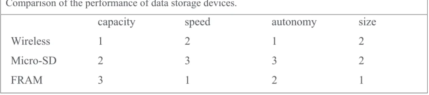
ARDUINO (Severance, Jan. 2014) has been the choice as a platform to control the miniature sensors. It has basically all the advantages searched for in this thesis: the design is open, and can be programmed in the C language, a standard independent for the operating system. On top, it can be assembled quite compactly, which facilitates its deployment into, for example, a sea rock. Sensors including a tri-axial accelerometer and a wireless module are controlled by the Arduino. For the data storage, several standards have been studied, considering different parameters, such as storage capacity, data acquisition speed, error margin in data transfer, operation autonomy –basically given by power consumption– and ability to control multiple sensors. So, for example, while Bluetooth excels in terms of storage capacity and autonomy, micro-SD cards is the choice when multiplicity is necessary. FRAM, on the other hand, is excellent both in terms of multiplicity and speed. These choices –always under the ARDUINO platform– are preliminary tried both in laboratory conditions (intruder penetrating into a shaken
INTRODUCTION
9 box of sand) and in natural conditions, when installed into rocks deployed in a Cuban sandy beach.
In summary, the basic goal of the thesis is to study the behavior of intruders in fluidized
granular matter, eventually creating new experimental techniques to achieve that goal.
In particular, the objectives of the thesis, are:
a) To determine the influence of the kind of basement in the behavior of a cylinder used as a model of a human construction or a rock, when it penetrates a vibrofluidized granular bed.
b) To establish the influence of gravity in the sinking of a spherical intruder into light granular matter, measured by wireless accelerometry.
c) To create an accelerometric technique suitable to study the slow penetration of an intruder into vibro-fluidized granular matter.
d) To implement an open-core and open-software Arduino-based platform to study the behavior of intruders into fluidized granular matter both in laboratory and in natural conditions.
Chapter
1 BASIC CONCEPTS.11
Chapter 1: Penetration Of Intruders Into Dry
Granular Media: Basic Concepts.
Penetration of solid objects into soils has been, for a long time, the reign of civil engineers, Earth scientists and astronomers. However, since the 1990’s the matter has become a physicists’ “hot topic”. In particular, during the last decade the “physical understanding” of the resistance to objects penetrating into granular media has advanced quickly (Albert, Pfeifer, Barabasi, & Schiffer, 1998) (Uehara, Ambroso, Ojha, & Durian, 2003) (Walsh, Holloway, Habdas, & deBruyn, 2003) (Tsimring & Volfson, 2005) (Katsuragi & Durian, Unified force law for granular impact cratering, 2007) (Goldman & Umbanhowar, 2008) (Pacheco-Vazquez, Caballero-Robledo, & al., 2011) (Boudet, Amarouchene, & als., 2006) (de Vet & de Bruin, 2007) (Chen, Umbanhowar, & als., 2009) (Brzinski & Durian, 2010) (Constantino, Bartell, & als., 2011) (Dorbolo, Ludewig, & Vandewalle, 2013) (Katsuragi, Nonlinear wall pressure of a plunged granular column., 2012) (Kondic, Fang, & als., 2012). In this chapter, a limited number of key results in that field will be briefly presented. Due to its direct connection to later chapters of the thesis, emphasis will be put on the slow penetration of intruders into granular matter –a typical example being an object that starts its motion from a rest position on the free granular surface. For a more general overview of the field, the recent review by C. Ruiz Suárez (Ruiz-Suarez, 2013) is recommended.
1.1 Some scaling laws for intruder penetration.
Tsimring & Volfson (2005) carried out low-speed impact experiments of solid objects into granular media, in order to reproduce geophysical events and to test the unusual nature of the granular state of matter. Their observations were interpreted in terms of conflicting stopping forces expressed as powers of projectile depth and speed. Depending on the case, these were linear in speed; constant, proportional to the initial impact speed; or proportional to depth. In order to study the resistance forces in granular media during impact and the mechanisms of energy dissipation the projectile size, density, and impact velocity, as well as friction among the grains were systematically varied in their experiences. They found a final or stop time which decreases with increasing impact speed. In addition –and unexpectedly– the experiments
12
PHYSICS AND ENGINEERING OF NATURAL CATASTROPHES
showed that deeper penetration requires less time. This suggested they that a single, “unified” force law underlies for all of the observations.
Tsimring and Volfson established the different ways for the energy redistribution during penetration (illustrated in Figure 1.1):
1. Lifting of grains during crater formation.
2. Inelastic collisions between the body and the grains and among the grains during
impact.
3. Friction due to particle sliding contacts and body-grain sliding.
bFigure 1.1 Energy dissipation of a spherical intruder sinking into a granular matter.
On the Figure 1.1 the simulation shows that the total energy of the intruder (kinetic plus potential) decreases as the penetration process takes place. In the end, most of it is dissipated as frictional energy, but inelastic collisions also contribute. The increase in the average potential
Chapter
1 BASIC CONCEPTS.13 energy of the grains also gets a fraction of the initial energy of the intruder (Figure adapted from Tsimring and Volfson, 2005).
At low speed, the energy losses on friction between the intruder and the grains is negligible.
For large impact energies, the kinetic friction term ,-/1 has to be taken into account, which
affects the initial phase of the object deceleration. Interestingly, the additional deceleration caused by the kinetic friction reduces the depth of penetration (it deviates from the linear scaling even for large penetration depths).
For small impact speeds, Durian & coworkers (Uehara, Ambroso, Ojha, & Durian, 2003) found the following scaling relationship between the crater depth d (defined as the distance between the unperturbed surface and the lowest point of the projectile at rest) and other parameters of the impact: 2 = 0.3456789: 9 ; < > ? @A : @ BC?B (1)
Here, ρg, ρb are densities of grains and the spherical intruder, respectively, μ is the grain-grain
friction coefficient defined through the repose angle of the grains θ, μ = tanθ, Db is the diameter
of the ball, and H is the total drop of the ball (the sum of the free-fall height D = EF1GH! and the
total penetration depth d).
From experiments at high impact velocity, (Ciamarra, Lara, Golman, Vishik, & Swinney, 2004) found that after a short initial phase, a “penetration phase” ensues, during which the deceleration of the ball a is roughly constant. This scaling implies that the stopping time is independent of the initial velocity, and the penetration depth is proportional to the square of the initial velocity:
2 = IJ@
1# (2)
A linear scaling between the ball penetration depth and the impact momentum mvo was reported
by de Bruyn & coworkers (Walsh, Holloway, Habdas, & deBruyn, 2003). The established theory of impact penetration (Forrestal & Luk, 1992)is based on the so-called Poncelet model,
which assumes that the force acting on the object consists of three components: gravity mbg,
static resistance force Fz, and dynamic frictional force αv2. Then the Newton’s law is written
as:
14
PHYSICS AND ENGINEERING OF NATURAL CATASTROPHES
where z(t) is the vertical coordinate of the lowest tip of the object with respect to the surface.
Integrating this equation with appropriate boundary conditions and assuming constant Fz yields
the so-called Poncelet formula for the maximum penetration depth:
2 = (H,+67QR!S3 T ,E
F1(PUO K:!+67V (4)
The dimensional parameter α is proportional to the cross section of the ball. This formula works reasonably well for medium- and high-speed impacts however it fails to describe low-speed impacts.
cFigure 1.2 Force diagram of an intruder sinking into granular matter. The gravity force
competes with two stopping forces pointing upwards.
Using 3D finite element simulations, Tsimring & Volfson generalize (3) and (4) in order to describe low-speed impacts. They focused on the depth-dependence of the static resistance force. Albert and co-workers showed experimentally (Albert, Pfeifer, Barabasi, & Schiffer, 1998) that in a slow drag regime the force acting on an object is proportional to its cross section times the local pressure. Following that, Tsimring & Volfson considered in the initial phase the
free surface fixed at z = 0, and the pressure as p = ρggz (here ρg is the effective density of the
granular material). In the penetration phase, the free surface moves down with the ball, so the
pressure under the ball can be taken as p = ρggzo. Here zo = z−zzf = cons = O(Db), where zzf is
Chapter
1 BASIC CONCEPTS.15 The 3D discrete element simulations, yields a “static drag force” as:
PM=WX9!M
HALY M Z AL
X9!M0HALY M [ AL (5)
Where η is a dimensionless parameter dependent on the material properties of the grains and the ball (e.g., friction coefficient).
For small impact energies, the 3D scaling agrees with the experimental results of Durian’s group (Uehara, Ambroso, Ojha, & Durian, 2003), and for larger impact energy the model describes the transition to the penetration phase with constant deceleration in agreement with Ciamarra and coworkers (Ciamarra, Lara, Golman, Vishik, & Swinney, 2004).
These results suggest that for small initial speeds, the penetration depth scaling is reasonably well described by the Poncelet equation (Eq. 4) with a depth dependent static friction force (Eq. 5).
1.2 The "unified force law" of Katsuragi & Durian.
Katsuragi & Durian agreed with Tsimring & Volfson in the sense that a single, unified, force law underlies all of the observations on their experiments. Tsimring & Volfson argued that the
form of Fz should vary from quadratic to constant owing to the shapes of the projectile and of
the growing crater excavated by its motion. Such a force law can approximately account for a
depth scaling\2\ = (2F1C+7 ]<. The order of magnitude of this force is larger than that expected
just from the Coulomb friction.
Katsuragi & Durian departed from the hypothetical formula:
^ P = OK! T PUT_I
@
16
PHYSICS AND ENGINEERING OF NATURAL CATASTROPHES
were Fz is the term for the Coulomb friction and the last one is the inertial drag and di is a
constant. Combining it with Newton’s second law, the acceleration at a given fixed depth zi
should be quadratic in speed\\b\ T !\ =\cda
_ T E 1
2e
< , where a is the acceleration of the intruder.
They did tries for several depths zi and found the same proportionality factor d1 for all depths.
The good agreement of this expression with the experimental results indicates that the projectile
experiences a force KE1 2
e
< that is independent of depth. In addition, they found an expression
for the inertial force required for the projectile to mobilize a volume A:] of granular material
with density ρg (KE1 2
e
< scaling as 0.8 ρgA:1E1).
Using the d1 value, they found an expression for the Coulomb’s friction term and even when
Tsimring & Volfson argued the quadratic to linear variation in the expression of the force, Katsuragi and Durian found that a linear fit worked well over most of the experimental range. This suggested the friction term to be:
PM= f|M| , f<K= 3.040 ± 30\-OH (7)
So the force law becomes:
^ P = OK! T f|M| T KE1< 2e\ (8)
with order of magnitude of KE1 2
e
< = 9;A:1E1 determined by the granular density and cross
section area of the penetrating body. The characteristic length scale is given by the diameter of
the body Lc=Db so the penetration depth is within an order of magnitude of the body diameter
for a wide range of impact speeds. The time is contained in the gravity term, so the characteristic
time and velocity scales as gh= (AL<!+3 H
i
, which explains the typical stopping time and the velocity beyond which the typical stopping time becomes constant. This force law described
Chapter
1 BASIC CONCEPTS.17 As the authors held “The only puzzles that remain are the linear form of the Coulomb friction
term plus the precise values of k and d1, as well as their scaling with system properties”.
1.3 Pacheco-Vázquez et al.: introducing Janssen's effect.
These achievements were insufficient to describe the dynamics when bodies penetrated inside granular media. Pacheco & coworkers in 2011 (Pacheco-Vazquez, Caballero-Robledo, & al., 2011) analyze the case when the depth-dependent force saturates with depth due to the presence of walls.
Reviewing the linear expression proposed by Katsuragi & Durian in 2007 (Katsuragi and Durian 2007) the term corresponding to Coulomb’s friction, should be dependent on the pressure, so, they incorporate the pressure p as a Janssen-type dependence on depth z:
(9)
Where ρ is the bulk granular density, g the gravity, and λ a characteristic length, close in value to the diameter of the container containing the granular material. Since according to this dependence the pressure saturates, the friction felt by a penetrating object must saturate as well, and a terminal velocity ought to be reached. The new force equation rewrites as follows:
KMN = K! O XM/1O fkl3 O m6U ni o (10)
The quadratic dependence in velocity is sufficient to describe the inertial drag, at least in loose granular materials like expanded polystyrene beads. For small penetrations, the friction term becomes linear and for large ones it is constant. The latter case explains the existence of a
terminal velocity Vt when the friction term reaches a value kλ at saturation, occurring when the
acceleration is zero. This lead to:
pgH =\K! X O fk Xi i (11)
Which implies that a critical mass exists, above which the intruder is able to penetrate an infinite
depth, reaching a terminal velocity equal to zero. This mass is given by Kh = fk !i (for smaller
/
( ) (1 z )
P z
r l
g e- l-18
PHYSICS AND ENGINEERING OF NATURAL CATASTROPHES
masses, the intruder eventually stops at some depth inside the granular silo, and, for bigger masses, it reaches a finite, constant terminal velocity).
In order to individually determine k and λ, we consider the balance between the weight of the
intruder and the depth-dependent force\K! = fk\l3 O mU ni o. Solving for z = zmin, the minimum
depth from were an intruder will not sink if it were “quasi-statically put there” with zero speed is:
MKqr = OkQr(3 O K! fki + (12)
Equations (10) – (12) will be eventually used in the present thesis to interpret penetration experiments into granular fluidized beds –both due to vibrations or to the shear produced by the intruder itself into very light granular matter.
Chapter
2 SINK VS TILT PENETRATION.19
Chapter 2: Sink Vs. Tilt Penetration Into Shaken
Granular Matter: The Role Of Foundation.
2.1 Article: G. Sánchez-Colina, A. J. Batista-Leyva, C. Clément, E. Altshuler and
R. Toussaint. Submitted (2016).
2.2 Supplementary information.
2.2.1 Experimental setup: further details.
2.2.2 Image processing: further details.
2.2.3 Fluidization and structural damage.
2.1 Article: G. Sánchez-Colina, A. J. Batista-Leyva, C. Clément, E.
Altshuler and R. Toussaint. Submitted (2016).
20
Chapter
2 SINK VS TILT PENETRATION.22
Chapter
2 SINK VS TILT PENETRATION.24
Chapter
2 SINK VS TILT PENETRATION.26
Chapter
2 SINK VS TILT PENETRATION.28
Chapter
2 SINK VS TILT PENETRATION.30
Chapter
2 SINK VS TILT PENETRATION.31
2.2 Supplementary information.
Our test cell is a 0.0156 m3 (25x25x25 cm3) acrylic cube filled to approximately 2/3 of the
volume with a grains bed. It was firmly fixed to a cradle driven over sliders with 0DOF (0 degrees of freedom) by a TIRA TV51120 shaker. The shaker governs the cradle through a rigid steel shaft. Fit to the front side of the cradle a Gopro HERO-II camera is recording the experimental sequences at 120 frames per second (fps), as it is pointing to the center of the cell transversely to the movement’s sense. We chose for the granular bed Ugelstad spheres of
non-expanded polystyrene with a density 1.05 g/cm3, and diameter 140 µm (monodisperse within a
1 percent).
The intruders were 44 mm height x 44 mm diameter 3D printed cylinders with 3 mm wide walls, made of alumide by Sculpteo. One of the cylinders has a flat bottom, imitating a mat foundation. The other one has a 5 mm high and 3 mm wide ring in the base as a circular strip foundation. A ballast inside the intruders make them isodense with the medium.
To warrant the loose condition on the medium, beforehand disposing the intruder on the surface, we plow with a stick along and cross the bed, deep to the bottom, until the grains present the least opposition. This step is mandatory, as the grain bed consolidates on every shaking session. Before we turn on the shaker, the camera is set to record, and then the shaker is on for around 20 s. Then backwards, first the shaker, then the recording is stopped up to set the next sequence. The camera records the image sequences at 120 fps in MP4 format. On the front face of the intruder, a pair of black patches vertically disposed, helps to tag the body in the frame with the image processing software. A flicker-free 400 W spotlight (Dedolight HMI) illuminates the experimental setup.
2.2.2 Image processing: further details.
Each sequence must be converted from MP4 form to a JPG sequence of color images before processed. The process is done with the help of MatlabR2014a. The task to translate to images is carried out with the FFMPEG software. The resulting image sequences are the input to a Matlab script that in general follows always the same algorithm, loading the frame, crop the image to keep the zone were the intruder will move along the frames, which reduces the pixels to process. The image is converted to gray scale and then filtered to homogenize the
32
PHYSICS AND ENGINEERING OF NATURAL CATASTROPHES
bright levels and then converted again to black and white (BW) taking a standard contrast level as a gray value binarization reference. The BW image is filtered again to isolate the black patches. The patches are the references to identify the center of mass and, consequently, the position of the intruder. At the same time, they trace a central line that traces the angular position giving us the angle and position change from frame to frame. The data returned in workspace variables is saved in a file after every session to be processed in a calculation sheet.
In some experiments the sloshing sand or reflects or glows in the cell surface spoils the images, then is necessary to apply more filtering or even to discard the patches as references. By instance, on the experiments that finish in a toppling cylinder, usually the patches goes into the grains surface. On these cases, the edges of the cylinder helps to track the position. This means that to program the script, we must inspect the video before, to assess if there are blurring of the image, if the marks are always visible, and if possible, to cut out useless frames to speed out the process. Some frames are much damaged when various sources of error combines, on these cases there is still the resource to measure the initial and final position of the intruder with another image process software, as ImageJ.
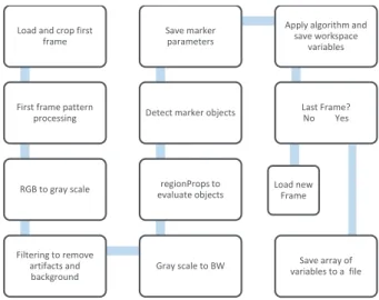
Figure 2.1 shows a block diagram of the image processing algorithm, which was implemented in Matlab. The corresponding script is explained below.
dFigure 2.1 Block diagram of the Matlab's image processing algorithm.
Load and crop first frame
First frame pattern processing RGB to gray scale Filtering to remove artifacts and background Gray scale to BW regionProps to evaluate objects Detect marker objects
Save marker parameters
Apply algorithm and save workspace variables Last Frame? No Yes Load new Frame Save array of variables to a file
Chapter
2 SINK VS TILT PENETRATION.33 The diagram on the figure shows the normal procedure carried out to calculate the position of the intruder’s center of mass position through the sequence of frames originated from the recorded experiment (see figure 2.2.2).
The first operation is to load the sequence into the Matlab’s work space:
close all clear all
filFolder = 'C:\Users\Owner\Documents\MATLAB\Nr5Hz300c\'; filePattern = dir(fullfile(filFolder,'noring_5Hz_300mV_c-*.jpg')); filNames = {filePattern.name}'; %Trasposing the pixels array cfilNames = filNames;
nFrames = numel(filNames); %Customized threshold and areas % nr5Hz300a gray - BW threshold 0.47 % nr5Hz300b gray - BW threshold 0.44
% nr5Hz200d gray - BW threshold 0.45 Area cn>130 % nr5Hz200b gray - BW threshold 0.47 Area cn>120 % noring_5Hz_300mV_c gray - BW threshold 0.47 cn>130 % noring_5Hz_400mV_a gray - BW threshold 0.5 cn> 80 Angle = 90; %Parameter to calculate angle
for p = 1:nFrames
rgb = imread(filNames{p}); %JPG frame to RGB
Next to loaded the images sequence, is to crop it to speed up the process avoiding to process pixels without useful information.The first frame is pre-processed to determine the position parameters of the intruder and the marks (shown as dark spots in Fig. 2.2). These parameters will be used as initial settings to process the subsequent frames, as follows:
%Cropping coordinates (was done by just tampering on the first frame ... %for each sequence) start_row = 50;%Works for all
start_col = 300;
% Crop the Image to save processing time
rgbcrop = rgb(start_row:300, start_col:700, :);
34
PHYSICS AND ENGINEERING OF NATURAL CATASTROPHES
Igr = rgb2gray(rgbcrop); %Convert to grayscale
L_HH = stretchlim(Igr); %Enhancing the contrast, see Matlab's example Ig = imadjust(Igr,L_HH,[]); dim = size(Ig); %Take the n of col and rows cn = 120; %Area, parameter for the mark to detect %it will change along the execution %of the algorithm
ix1 = 1; %Reset the order number for ix2 = 2; %the detected areas %%%%%%%%%%%%%%%%%%%%%%%%%%%%%%%%%%%%%%%%%%%%%%%%%%%%%%%%%%% %Clearing the background
Ibw = im2bw(Ig, 0.47); %starting threshold for the sequence if Angle < 80 %Adjust the threshold for shadows Ibw = im2bw(Ig, 0.5); %on tilted images end
%figure, imshow(Ibw), title('Erased bkground'); %%%%%%%%%%%%%%%%%%%%%%%%%%%%%%%%%%%%%%%%%%%%%%%%%%%%%%%%%%%%%%%%%%%%%%%%%% %Create mask for the marks on the intrus
Igm = immultiply(Ig, ~Ibw); %Isolating Marks on the grayscale image % figure, imshow(Igm), title('Raw Gris'); Ig = imfill(~Igm,'holes'); %Cleaning some spureous marks %figure, imshow(Ig), title('Ig Mask after imfill'); %%%%%%%%%%%%%%%%%%%%%%%%%%%%%%%%%%%%%%%%%%%%%%%%%%%%%%%%%%%%%
%Further cleaning Marks Marks = immultiply(Igm,Ig);
% figure, imshow(Marks), title('Igm xIg mask'); IM =(Marks*2);
Ibwm = im2bw(IM);
Ibxm = imfill(Ibwm,'holes'); me = [9 5];
se = strel('Rectangle', me);% Ibm = imclose(Ibxm, se);
% figure, imshow(Ibm), title('Preprocessed Frame');
%%%%%%%%%%%%%%%%%%%%%%%%%%%%%%%%%%%%%%%%%%%%%%%%%%%%%%%%%%%% %Taking the first frame as a pattern
if p == 1 CC = bwconncomp(Ibm); S = regionprops(CC, 'Area','BoundingBox','Extrema'); NE = numel(S); L = labelmatrix(CC); Arefs = [S.Area]; [Ai,in]=sort(Arefs,'descend');
cn = Ai(2)-1; %Sets the lower boundary for the area [RfArea,Adx]=max(Arefs);
BW1 = ismember(L, find([S.Area] > cn));
ColLimExtr = S(Adx).Extrema(:,1)+20;%Sets the boundary to find the intrus %upper point + 20 pixels
% figure, imshow(BW1), title('Region #1'); %Again regionprops to erase side shadow
Chapter
2 SINK VS TILT PENETRATION.35
% if p == 1 %Just to be used to tamper in a test frame CC0 = bwconncomp(BW1);
S0 = regionprops(CC0,'Area','Extrema'); L0 = labelmatrix(CC0);
ATops = [S0.Area];
[MaArea,Aidx]=max(ATops);
%Deleting spureous bodies to the right of the marks
BWI = ismember(L0, find(S0(Aidx).Extrema(:,1) < ColLimExtr));
% figure, imshow(BWI), title('Frame #1 first marks');
CC1 = bwconncomp(BWI);
S1 = regionprops(CC1, 'Area','Centroid','BoundingBox','Extrema'); L1 = labelmatrix(CC1);
Lmap = label2rgb(L1,'lines','k');
% figure, imshow(Lmap), title('Frame #1 second marks'); %Taking the centers of the Mark to be used as a beginning pattern
Frstcenter=S1(1).Centroid;%(col,row) Scndcenter=S1(2).Centroid;
RefCenter = vertcat(Frstcenter,Scndcenter); end
%%%%%%%%%%%%%%%%%%%%%%%%%%%%%%%%%%%%%%%%%%%%%%%%%%%%
The marker is isolated from the background pixels after cropping the region of interest by means of a polygonal mask. The polygon is placed taking the coordinates from the previous frame’s mask. These parameters are updated by the corresponding parameters from the regionProps structure in the region comprising the mark:
%Here starts the processing of the sequence if p ~= 1
%%%%%%%%%%%%%%%%%%%%%%%%%%%%%%%%%%%%%%%%%%%%%%%% % Pick the marks by check the matching points if RefCenter(3)> RefCenter(4) st = RefCenter(3); RefCenter(3)= RefCenter(4); RefCenter(4)= st; st = RefCenter(1); RefCenter(1)= RefCenter(2); RefCenter(2)= st; end refCol = RefCenter(:,1)'; refRow = RefCenter(:,2)'; BW2 = bwselect(Ibm,refCol,refRow,4);
% figure, imshow(BW2), title('Matching Points'); CC1 = bwconncomp(BW2); %Reuse CC1 to spend memory space S1 = regionprops(CC1, 'Area','Centroid','BoundingBox');
36
PHYSICS AND ENGINEERING OF NATURAL CATASTROPHES
Nl = numel(S1);
if Nl~=2 %If one of the marks isn't detected expand the search ci = refCol(1) -30; cd = refCol(2) +30; ru = refRow(1) -20; rl = refRow(2) +20; c = [ci ci cd cd]; r = [ru rl rl ru]; MBW = poly2mask(c,r,dim(1),dim(2)); % figure, imshow(MBW),title('Mask 2'); BW2 = immultiply(Ibm,MBW);
% figure, imshow(BW2),title('New centers'); CC1 = bwconncomp(BW2); S1 = regionprops(CC1, 'Area','Centroid','BoundingBox'); Nf = numel(S1); end L1 = labelmatrix(CC1); Lmap = label2rgb(L1,'lines','k'); Arnw = [S1.Area]; [An,in]=sort(Arnw,'descend');
ix1 = in(1); %Sort the areas ix2 = in(2);
% figure, imshow(Lmap), title('N processed Frame'); % hold on;
end
Frstcenter=S1(ix1).Centroid; %(col,row) Scndcenter=S1(ix2).Centroid;
Center = vertcat(Frstcenter,Scndcenter);
The Mark is identified amid of the objects as the one with the biggest area:
if p ==1
RefCenter = Center; % break;
else
DfCenter = RefCenter - Center; RefCenter = Center;
end
%%%%%%%%%%%%%%%%%%%%%%%%%%%%%%%%%%%%%%%%%%%%%%%%%%%%%%%%%%% % Finding line between centers to calculate angle
linvec = polyfit(Center(:,1),Center(:,2),1);%polyfit(x,y,n) % linx = [0 dim(1)];
Chapter
2 SINK VS TILT PENETRATION. 37 % Hallar angulo if Center(1)== Center(2) Ang = 90; % AngI = 90; elsevect1 = [1 linvec(1)]; % create a vector based on the line equation vect2 = [1 0];
dp = dot(vect1, vect2); % compute vector lengths length1 = sqrt(sum(vect1.^2)); length2 = sqrt(sum(vect2.^2));
A =(acos(dp/(length1*length2))*180/pi);
% obtain the larger angle of intersection in degrees if linvec(1)< 0
Ang = acos(dp/(length1*length2))*180/pi;
% AngI = 180 - atand(linvec(1)); %Doesn't works else
Ang = (acos(dp/(length1*length2))*180/pi); AngI = atand(linvec(1));
end end
After extracting the X-Y coordinates of the mark over the complete sequence of images, and the inclination based on the X-Y coordinates of both marks, those parameters are exported, from the Workspace to a txt file:
Angle(p,1) = (Ang); %Angles including the first frame % Angle(p,1) = (AngI);
ROW(p,1)= (Center(1)); COL(p,1) = (Center(3)); YXA = horzcat(ROW,COL);
YXA = horzcat(YXA,Angle);%incorporate all the vectors to the array end
%Run this function in the command window to save a file % save('Nr5Hz300c.txt', 'YXA','-ascii','-tabs');
38
PHYSICS AND ENGINEERING OF NATURAL CATASTROPHES
2.2.3 Fluidization and structural damage.
Structural damage and fluidization in real buildings are linked complex ways. For example, modern buildings in Adazapari, Turkey, were mostly 3 to 6 story reinforced concrete structures with firm reinforced concrete mat foundations. After undergoing ground failures, many structures moved without substantial structural damage (Bray & Dashti, 2010). Many of the structures settled into the soil without tilt.
Tilting of structures after the earthquake without significant physical damage was attributed to the behavior of these foundations, which allows the building to respond more as a rigid body while it undergoes significant differential downward movement, tilt, or lateral translation. Tilt or toppling was related in many buildings to be laterally unconstrained with high aspect ratios (Sancio, Bray, & als., 2004). This effect had been observed before in the 1964 Niigata and 1990 Luzon earthquakes, typically in corner buildings, in buildings without adjacent structures on one or both sides, in buildings surrounded by lightweight structures, and in those parts of the area where there was greater separation between adjacent buildings (Liu & Dobry, 1997). The structural damage was more significant for buildings with individual footing allowing differential settlements. New buildings with continuous and mat foundations settled and/or tilted as a whole, with little damage to the superstructure (Liu & Dobry, 1997). All of these observations pointed to the importance of the confining effect of the whole building and adjacent structures in reducing the level of settlement. In current design practice, a liquefiable soil deposit would be treated before a new structure is built on it. In fact, it is a well-established fact that there is a relationship between parameters as the width of the foundation, the thickness of the liquefied layer, and the foundation contact pressure, to displacements of foundations on granular soils. In model tests, it has been found that the vertical foundation movement is inversely proportional to the foundation width. (Liu & Dobry, 1997).
However, a building settlement is also affected by a large number of other variables that cannot be independently assessed. Hence, the development of engineering tools for evaluating the consequences of liquefaction on building performance warrants more attention. Perhaps the experiments previously described in this chapter may help to establish a laboratory framework
Chapter
2 SINK VS TILT PENETRATION.39 to determine the effect of each individual feature of a building’s foundation when the soil is fluidized.
In fact, the experiments reported in the present chapter study a variable usually overlooked in the study of the behavior of the building stressed by a seism: the shape of the foundation. Architecture establishes a diversity of foundations, grouped under the shallow or depth foundation classifications. Shallow foundations are by large the most used for household buildings, because they are technologically easy and affordable –it is perhaps reasonable to identify them with the flat-bottom cylinders studied earlier in the present chapter. Shallow foundations are also the most affected by soil fluidization in earthquakes. With this motivation, we headed the experiments to study the mat or raft foundations, and the circular footing (strip, continuous spread or wall footing). Depth foundations, as pillars, usually go down to the bedrock or up to the safe zone where there is no chance of liquefaction –such foundations could be identified with the ring-shaped basement cylinders. Then, it seems reasonable as a future research track to make a careful survey of sink and tilt effects of earthquakes on real buildings with shallow and depth foundations, and compare them with the laboratory results reported earlier in the present chapter.
Chapter
3 SETTLING INTO DRY GRANULAR MEDIA.41
Chapter 3 Settling into dry granular media in
different gravities.
3.1 Article: E. Altshuler, H. Torres, A. González-Pita, G. Sánchez-Colina, C.
Pérez-Penichet, S. Waitukaitis and R. C. Hidalgo, Geophysical Research Letters
41, 3032 (2014).
3.2 Supplementary information.
3.2.1 Experimental setup: further details.
3.2.2 Discrete elements simulations: further details.
3.2.3 Article: H. Torres, A. González, G. Sánchez-Colina, J. C. Drake and E.
Altshuler, Revista Cubana de Física, 29, 1E45 (2012).
3.1 Article: E. Altshuler, H. Torres, A. González-Pita, G.
Sánchez-Colina, C. Pérez-Penichet, S. Waitukaitis and R. C. Hidalgo,
Geophysical Research Letters 41, 3032 (2014).
42
Chapter
3 SETTLING INTO DRY GRANULAR MEDIA.44
Chapter
3 SETTLING INTO DRY GRANULAR MEDIA.46
Chapter
3 SETTLING INTO DRY GRANULAR MEDIA.48
PHYSICS AND ENGINEERING OF NATURAL CATASTROPHES
3.2 Supplementary information.
3.2.1 Experimental setup: furher details.
The granular media consists of expanded polystyrene particles with a density of 0.014 ± 0.002 g/cc and diameters ranging from approximately 2.0 to 6.5 mm (with a peak at 5.8 mm). To ensure that the system has a similar initial configuration each experiment, we use the following procedure adapted from Torres et al. (Torres et. al, 2012): First, we inject air from below through a wire mesh with a pressure ramp just until the top of the bed just becomes fluidized. Then we slowly lower the pressure until there is zero flow. Next, we shake the container horizontally for 5 seconds (the oscillations are approximately sinusoidal, with a period of 0.225 ± 0.004 s and
an acceleration amplitude of 1.9 ± 0.3 m/s2). This process repetitively produces a volume
fraction of 0.68 ± 0.01 and maximum angle of stability of 30.29o ± 0.50o.
The sphere is quickly released into free-fall with the aid of a magnetic latch. The exact moment of release is determined by remotely observing the bucket acceleration with a computer and,
once it is confirmed that the bucket moves with constant acceleration geff, deactivating the latch.
Care is taken to ensure that little lateral motion occurs and that at release the bottom of the sphere is just gently touching the free granular surface. The 3-axis accelerometer inside the sphere has a resolution of 10−4g and is able to transmit data in real time at 2.4 GHz to a USB node on an external PC at a data point rate of 120 Hz. The device had a saturation acceleration
of s 8g (Freescale semiconductor, 2009).
3.2.2 Discrete elements simulations: further details.
We use discrete element modeling (DEM) to simulate a large sphere sinking into a granular bed composed of smaller spheres (Poschel & Schwager, 2005). The implementation is a hybrid CPU/GPU algorithm that allows us to efficiently evaluate the dynamics of several hundred thousand particles (Hidalgo, Kanzaki, Alonso-Marroquin, & Luding, 2013), (Longmore, Marais, & Kuttel, 2013) (Owens, Houston, Luebke, & als., 2008). We initiate each simulation
Chapter
3 SETTLING INTO DRY GRANULAR MEDIA.49 by generating a random granular packing of monodisperse spheres (radius r and density ρ) at
packing fraction φ = 0.62 ± 0.02. The spherical intruder (R = 8r and density ρint = 50ρ) is
released from the free granular surface with zero initial velocity.
For each particle i = 1…N the DEM simulation includes three translational degrees of freedom and the rotational movement is described by a quaternion formalism. The interaction force
between particle i and particle j, is composed by normal and tangential components Pteu = Pteuv
+Pteu). In our approach, the normal interaction force between the particles Pteuv depends
non-linearly on the particles overlap distancew. Moreover, the local dissipation is introduced by a
non-linear viscous damping term, which depends on the normal relative velocity\Exxxt$yzv . Hence,
the total normal force reads as\Pxxxteuv = OfvwB@r{ O }vKyEt$yzv w?~, where kn and }v represent elastic
and damping coefficients and me = mimj /(mi + mj ). The tangential component Pteu)also includes
an elastic term and a viscous term, Pteu) = f)•t O })KyEt$yz) , where }) is a damping coefficient
and Et$yz) is the tangential relative velocity of the overlapping pair. The variable |•t| represents the
elongation of an imaginary spring with elastic constant kt. As long as there is an overlap between
the interacting particles, •t increases as d•t/dt = Et$yz) (Pöschel and Schwager, 2005). The elastic
tangential elongation •t is kept orthogonal to the normal vector (Weinhart et. al, 2012) and it is
truncated as necessary to satisfy the Coulomb constraint |Pteu) | <µ|Pteuv |, where µ is the friction
coefficient.
The translational and rotational motion of each particle is governed by the Newton’s equation of motion,
^ Pt€u‚7• euT K!{= K`Ixt`) (1)
and
^ lƒt€u‚7• eu„\Pteuo= ƒ`…`)xxt (2)
In Eq (1) and Eq (2), the sums run over the Nc contacting particles of particle i. Moreover, the
intensity of the gravitational field is represented by\!†. The mass m and the moment of inertia I
= 2/5 m R2 are input parameters and the branch vector ƒteu characterizes the vector from the