Publisher’s version / Version de l'éditeur:
Proceedings, 31st annual meeting of the Adhesion Society, 2008
READ THESE TERMS AND CONDITIONS CAREFULLY BEFORE USING THIS WEBSITE.
https://nrc-publications.canada.ca/eng/copyright
Vous avez des questions? Nous pouvons vous aider. Pour communiquer directement avec un auteur, consultez la première page de la revue dans laquelle son article a été publié afin de trouver ses coordonnées. Si vous n’arrivez pas à les repérer, communiquez avec nous à [email protected].
Questions? Contact the NRC Publications Archive team at
[email protected]. If you wish to email the authors directly, please see the first page of the publication for their contact information.
NRC Publications Archive
Archives des publications du CNRC
This publication could be one of several versions: author’s original, accepted manuscript or the publisher’s version. / La version de cette publication peut être l’une des suivantes : la version prépublication de l’auteur, la version acceptée du manuscrit ou la version de l’éditeur.
Access and use of this website and the material on it are subject to the Terms and Conditions set forth at
Time-dependent crack growth in adhesive joints
Eskandarian, M.; Mathieu, F.; Papini, M.; Spelt, J. K.
https://publications-cnrc.canada.ca/fra/droits
L’accès à ce site Web et l’utilisation de son contenu sont assujettis aux conditions présentées dans le site LISEZ CES CONDITIONS ATTENTIVEMENT AVANT D’UTILISER CE SITE WEB.
NRC Publications Record / Notice d'Archives des publications de CNRC:
https://nrc-publications.canada.ca/eng/view/object/?id=dd785efe-5b9e-4cdc-a6e3-06218efc3d01 https://publications-cnrc.canada.ca/fra/voir/objet/?id=dd785efe-5b9e-4cdc-a6e3-06218efc3d01Time-dependent crack growth in adhesive joints
M. Eskandarian
1, F. Mathieu
2, M. Papini
3and J.K. Spelt
41) Aluminium Technology Centre, Industrial Materials Institute, National Research Council Canada (ATC/IMI/NRC), 501
boul. de l'Université, Chicoutimi (Québec), Canada G7H 8C3, [email protected]
2) École Polytechnique Montréal, 2900, boul. Édouard-Montpetit, Campus de l'Université de Montréal, 2500, chemin de
Polytechnique, Montréal (Québec), Canada H3T 1J4
3) Department of Mechanical and Industrial Engineering, Ryerson University, 350 Victoria Street, Toronto, Ontario,
Can-ada M5B 2K3
4) Department of Mechanical and Industrial Engineering, University of Toronto, 5 King’s College Road, Toronto, Ontario,
Canada M5S 3G8, [email protected]
Introduction
Structural adhesives like any other polymeric material exhibit time-dependent properties and can fail under long-term sustained loads well below those corresponding to quasi-static fracture. This phenomenon is commonly re-ferred to as creep rupture or time-dependent crack growth. Below the glass transition temperature, Tg, adhesives are
normally modeled as elastic materials for the duration of quasi-static tests. However, to make reliable joints, time-dependant behavior needs to be taken into account in the fracture load prediction of adhesive joints subject to pro-longed loading.
A design methodology accounting for the time-dependent fracture of adhesive joints has been developed in terms of viscoelastic fracture mechanics [1, 2]. It was demonstrated that wedge tests may be used to determine an effective threshold energy release rate for no creep crack growth in planar joints bonded either by a mineral-filled or a rubber-toughened epoxy adhesive. In the present study, a similar approach was followed to study the time-dependent crack growth in adhesive joints made of aluminum bars bonded by a heat-cured toughened epoxy adhesive, which was much tougher and more viscoelastic than the adhesive used in the previous study. This new adhesive demon-strated rate dependent effects and creep even during the short-duration quasi-static testing.
A series of wedge tests have been carried out on dou-ble cantilever beam joints (DCB) in accordance with ASTM D3762-79. The objective of wedge tests was to study the time-dependent crack growth in adhesive joints at various temperatures. The results were then used to ana-lyze the creep contribution to the fracture behavior of the same adhesive system in quasi-static tests at mode-I. The effects of substrate material and mode ratio were also in-vestigated by performing fixed-displacement mixed-mode relaxation tests on DCB joints made of aluminum and steel tested under different loading modes.
Specimens and test methods
The DCB specimens were fabricated from aluminum 6061-T651 and steel AISI 4140 flat bars (thickness 12.7
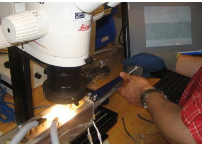
mm) bonded with a 0.4 mm thick layer of toughened ep-oxy adhesive. The aluminum parts were abraded, de-greased and then surface pretreated (P2-etch) while the steel parts were only abraded and degreased prior to bond-ing. The specimens were then tested at various tempera-tures and mode ratios by using two different test setups. In the first set of experiments, the DCB specimens were par-tially debonded through a quasi-static fracture test at room temperature. A stainless steel wedge with a nominal thick-ness of 1/8 inch was then manually inserted into the cracked specimen while the materials testing machine was applying a load close to that causing fracture (Figure 1). The force was removed at this moment and the assembly was installed on the linear stage of a stereo-microscope for crack length visualization. The crack was initially forced for a crack propagation of not more than 2 mm. The crack length was then optically measured in logarithmic time intervals for a period of a week having the room tempera-ture and humidity recorded four times a day.
A similar test procedure was followed for the wedge tests at higher temperatures where the DCB specimen was installed in an insulated temperature-controlled chamber (Figures 1 and 2). Temperature stability and uniformity across specimen were verified and maintained within 1 °C of the required temperature during the procedure. In this case the wedge was inserted as the DCB remained in the oven using a manual screw-driven apparatus (Figure 2).
Figure 1. Manual wedge insertion into loaded DCB speci-men installed in MTS electromechanical testing machine.
Figure 2. Initial wedge insertion into DCB specimen in-stalled in temperature-controlled chamber.
In a third set of experiments, the effects of adherend material and mode ratio on time-dependent crack growth were investigated by conducting a series of mixed-mode relaxation tests on DCB specimens by using the load jig of Ref. [3] shown in Figure 3. The normal quasi-static frac-ture test was followed by a relaxation test for a duration of a week with the reference time considered at the end of the last loading step. When a DCB is held in the fixed grip condition, stable creep crack growth can be observed since the energy release rate decreases with crack length. The crack length, load and pin opening were recorded in loga-rithmic time intervals by using a stereo-microscope mounted on linear stage, load cell of the testing system, and a laser extensometer, respectively. For both series of tests, the preliminary quasi-static fracture tests were con-tinued until a steady state damage zone was developed. The value of the critical energy release rate GcE in the
quasi-static test, as well as its threshold value for no creep crack growth Gth, were assumed to be unaffected by
adher-end plastic deformation or interfacial debonding, because the adherends remained elastic and the fracture was cohe-sive in all the cases.
Figure 3. Mixed-mode time-dependent crack growth at a phase angle of 48º using the load jig of Ref. [3].
Results and Discussion
The wedge and fixed-displacement tests have been conducted in order to estimate the maximum load or, equivalently, the applied energy release rate G without any appreciable time-dependent crack growth. An expression for G in terms of the relative displacement of the adher-ends in the wedge location is given in Ref. [1] on the basis of a beam-on-elastic-foundation model. 2 2 2 3 2 3 3 2 ) 3 / ( 48 ) ( ) / 1 (
β
β
β
δ
a a a a h h Eh G a I + + + − = 1where δ denotes the adherend opening displacement in the wedge location, E and Ea are the Young’s modulus of the
adherends and adhesive, respectively, h is the half-height of the DCB specimen, ha is the half-height of the adhesive
layer, a is the crack length relative to the wedge location, and the formulation for β is given as:
4 / 1 3 1 2 1 1 667 . 0 ⎪⎭ ⎪ ⎬ ⎫ ⎪⎩ ⎪ ⎨ ⎧ ⎥ ⎥ ⎦ ⎤ ⎢ ⎢ ⎣ ⎡ ⎟⎟ ⎠ ⎞ ⎜⎜ ⎝ ⎛ − ⎟ ⎠ ⎞ ⎜ ⎝ ⎛ + ⎟ ⎠ ⎞ ⎜ ⎝ ⎛ − = a a a E E h h h h h β 2 δ a h - ha 2 × ha h - ha Steel wedge
Figure 4. Wedge loaded DCB specimen and dimensions. Figure 5 shows the curves for the variation of crack extension as a function of time for the DCB specimens with wedges inserted at room temperature. The test data for different specimens are affected by the different initial crack extension conditions, because a plastic mallet was used rather than the more precise wedge insertion mecha-nism for the first two tests. However, the crack speeds are similar for all three cases.
Figure 5. Time-dependent crack propagation in three typi-cal wedge tests on aluminum DCBs at 22°C.
ime, sec 70 75 80 85 90 95 0 100 000 200 000 300 000 400 000 500 000 600 000 T C rac k l e n g th a, mm Specimen 4b test #1 Specimen 4b test #2 Specimen 5a test #3
Similar tests were conducted on aluminum DCB specimens tested at 80°C, for which the initial crack was produced by using the wedge-driven mechanism. The semi-logarithmic variation of crack length as a function of time is shown in Figure 6. The total crack advancement was 15.2 mm, more than twice that at 22°C (6.2 mm). The critical energy release rate, GcE, was determined from
quasi-static fracture tests (specimens 4b: 3458 J/m2, 5a: 3713 J/m2, and 5c: 3275 J/m2) and used for normalizing the data. Over a typical experimental timescale (maximum of one week), about 40% and 50% energy relaxations were observed at temperatures of 22°C and 80°C, respectively. The threshold value of G for no creep crack growth was still not reached after a week, but a power law expression, predicted from creep theory (Ref. [1]), was fitted to the combined data set as shown in Figure 7.
70 75 80 85 90 95 100 105 1 10 100 1 000 10 000 100 000 1 000 000 Time, sec C rack le ngt h a, m m Specimen 5c test #1 Specimen 5c test #2 Specimen 5c test #3
Figure 6. Time-dependent crack propagation in three typi-cal wedge tests on aluminum DCBs at 80°C.
Figure 7. Normalized energy release rate for crack propa-gation in aluminum DCBs wedge tested at 22 and 80°C.
Figure 8 shows that creep crack growth occurred much more quickly at mode I than at a phase angle of 48°. Furthermore, Figure 8 illustrates that there was no signifi-cant material dependency in creep behavior of adhesive joints made from aluminum and steel adherends.
Figure 8 Normalized energy release rate for crack propa-gation in DCBs tested at mode-I and 48°.
Conclusions
The data can be used to estimate the energy release rate with no appreciable crack growth at different tempera-tures and mode ratios. The designer may use the fracture mechanics test data in combination with these data to pre-dict the maximum applied load sustainable by a planar adhesive joint subject to mixed-mode loading. The lowest normalized G threshold value was obtained under mode-I loading at higher temperature (50% of quasi-static value after a week).
Acknowledgements
The authors wish to acknowledge the Natural Sciences and Engineering Research Council of Canada, Ontario Centers of Excellence, General Motors of Canada, and the Aluminum Technology Centre of the National Research Council Canada for their financial support.
References
1. D. Plausinis and J.K. Spelt, Designing for time-dependent crack growth in adhesive joints, Int. J.
Ad-hesion and Adhesives, 1995, 15, pp. 143-154.
2. D. Plausinis and J.K. Spelt, Application of a new con-stant G load-jig to creep crack growth in adhesive joints, Int. J. Adhesion and Adhesives, 1995, 15, pp. 225-232.
3. G. Fernlund and. J.K. Spelt, Mixed-mode fracture characterization of adhesive joints, Compos. Sci.
Technol., 1994, 50, pp. 441-449. Mode - I
48 deg.,
Aluminum and steel 0.0000001 0.000001 0.00001 0.0001 0.001 0.01 0.1 1 0.5 0.6 0.7 0.8 0.9 1.0 G / GcE da/d t, mm
Combined data 48 deg.: da/dt = 0.0357 (G/GcE)40.999
R2 = 0.7392 Combined data at mode -I : da/dt = 0.1691 (G/GcE)23.527 R2 = 0.9098 Combined data 80°C: da/dt = 0.2974*(G/GcE)14.721 R 2 = 0.8699 Combined data 22°C: da/dt = 0.1691*(G/GcE)23.527 R2 = 0.9098 0.000001 0.00001 0.0001 0.001 0.01 0.1 1 0.3 0.4 0.5 0.6 0.7 0.8 0.9 1 G/GcE da/d t, mm/ s 22°C 80°C