Publisher’s version / Version de l'éditeur:
Vous avez des questions? Nous pouvons vous aider. Pour communiquer directement avec un auteur, consultez la première page de la revue dans laquelle son article a été publié afin de trouver ses coordonnées. Si vous n’arrivez pas à les repérer, communiquez avec nous à [email protected].
Questions? Contact the NRC Publications Archive team at
[email protected]. If you wish to email the authors directly, please see the first page of the publication for their contact information.
https://publications-cnrc.canada.ca/fra/droits
L’accès à ce site Web et l’utilisation de son contenu sont assujettis aux conditions présentées dans le site
LISEZ CES CONDITIONS ATTENTIVEMENT AVANT D’UTILISER CE SITE WEB.
Concrete under Severe Conditions: Environment and Loading. Proceedings of the
6th International Conference on Concrete Under Severe Conditions
(CONSEC'10), Merida, Yucatan, Mexico, 7-9 June 2010, 2, pp. 65-73, 2010-06-07
READ THESE TERMS AND CONDITIONS CAREFULLY BEFORE USING THIS WEBSITE.
https://nrc-publications.canada.ca/eng/copyright
NRC Publications Archive Record / Notice des Archives des publications du CNRC :
https://nrc-publications.canada.ca/eng/view/object/?id=ced523ec-29ea-4345-a6bd-28b7f4dba7ac https://publications-cnrc.canada.ca/fra/voir/objet/?id=ced523ec-29ea-4345-a6bd-28b7f4dba7ac
NRC Publications Archive
Archives des publications du CNRC
This publication could be one of several versions: author’s original, accepted manuscript or the publisher’s version. / La version de cette publication peut être l’une des suivantes : la version prépublication de l’auteur, la version acceptée du manuscrit ou la version de l’éditeur.
Access and use of this website and the material on it are subject to the Terms and Conditions set forth at
Experimental simulation of surface cracking in concrete structures
affected by AAR
Ex pe rim e nt a l sim ula t ion of surfa c e c ra c k ing in c onc re t e st ruc t ure s
a ffe c t e d by AAR
N R C C - 5 1 1 7 1
N e r y , G . ; C u s s o n , D . ; H e l e n e , P . ; M a r g e s o n ,
J . C .
J u l y 2 0 1 0
A version of this document is published in / Une version de ce document se trouve dans:
6th International Conference on Concrete under Severe Conditions, Environment
& Loading (CONSEC'10), Mérida, Yucatán, Mexico, June 7-9, 2010, pp. 65-73
The material in this document is covered by the provisions of the Copyright Act, by Canadian laws, policies, regulations and international agreements. Such provisions serve to identify the information source and, in specific instances, to prohibit reproduction of materials without written permission. For more information visit http://laws.justice.gc.ca/en/showtdm/cs/C-42
Les renseignements dans ce document sont protégés par la Loi sur le droit d'auteur, par les lois, les politiques et les règlements du Canada et des accords internationaux. Ces dispositions permettent d'identifier la source de l'information et, dans certains cas, d'interdire la copie de documents sans permission écrite. Pour obtenir de plus amples renseignements : http://lois.justice.gc.ca/fr/showtdm/cs/C-42
Experimental simulation of surface cracking in concrete structures
affected by AAR
G. Nery
1, D. Cusson
2, P. Helene
1& J. C. Margeson
21
Escola Politécnica da Universidade de São Paulo, São Paulo-SP, Brazil
2
National Research Council Canada, Ottawa, Ontario, Canada
ABSTRACT: Alkali-aggregate reaction (AAR) is a slow expansive reaction that occurs in con-crete between the alkali in cement and reactive aggregates, leading to spalling and strength loss of the concrete. This reaction takes years to develop and the speed of reaction depends on sever-al materisever-al and environmentsever-al parameters. In order to develop and test corrective solutions to this problem in a reasonable laboratory timeframe, it is possible to accelerate AAR by using ex-tremely reactive materials under carefully controlled environments. This paper presents a new approach that was developed to simulate AAR-like expansion and random surface cracking in just a few days without the need for a controlled environment. After testing different approach-es, the successful approach consisted of the combined use of pervious concrete and expansive cement paste. It was found that the cracking patterns obtained on cylindrical and prismatic con-crete specimens were very similar to those found in real structures affected by AAR.
1 INTRODUCTION
Alkali-aggregate reaction (AAR) is a very slow deleterious reaction that occurs in concrete be-tween the alkali in cement and silicon dioxide found in common aggregates. This reaction pro-duces a gel that expands in contact with the moisture in concrete, which can lead to spalling and strength loss of the concrete and ultimately to the failure of the affected structure. This problem is known to affect large concrete structures, however, severe cases of AAR were recently ob-served in building foundations of smaller concrete structures. For instance, Andrade (2006) pre-sented eight confirmed cases of AAR in Recife-PE, Brazil. It was emphasized that this problem of AAR in small concrete structures could be more common than what is actually known to the scientific community. The rehabilitation of AAR-affected structures represents a considerable engineering challenge and the corrective actions are usually costly, especially for building foun-dations that are not directly accessible, often requiring the demolition of the concrete slab and excavation to gain access to the buried foundation. Once the repair work is completed and the area reopened for use, it is very difficult to evaluate the long-term effectiveness of the corrective action and the possible re-occurrence of the problem. The prediction of the progress (or lack) of the deterioration is uncertain, as different deterioration rates can be observed in structures, even made of similar concretes, because deterioration rates are strongly dependent on the various ex-posure conditions to which these structures are subjected (Fournier et al. 2009).
One of the possible ways to manage the AAR problem in building foundations is to monitor their expansion until some specific threshold values are reached, thus indicating the need to take corrective actions. Existing remote monitoring strategies for small AAR-affected structures with specific needs are scarce. In order to develop a monitoring strategy for AAR in small concrete structures, it became necessary to simulate the AAR expansion and cracking within a reasonable laboratory timescale, as AAR usually take years to develop in the field. It is possible to
6th Intl Conference on Concrete Under Severe Conditions Environment and Loading, Merida, Mexico, June 7-9, 2010
rate the AAR process by using extremely reactive materials under carefully controlled environ-ments in order to obtain typical AAR-like crack patterns and intensity. For example, Toma et al. (2007) achieved a simulation of AAR in concrete using an expansive agent based on lime hy-dration under wet curing and isothermal conditions. They obtained a 0.7% restrained expansion after 6 days, but the crack pattern was different from AAR-like cracking since the cracks had small openings and a preferential orientation. A new approach was therefore developed to simu-late AAR-like expansion and random surface cracking in just a few days without the need for a controlled environment. The whole process of developing the material formulations for achiev-ing the desired expansion and crack pattern is presented in this paper, while the structural health monitoring aspect of this study is presented in a companion paper (Nery et al. 2010).
2 DEVELOPMENT OF APPROACH TO SIMULATE AAR EXPANSION & CRACKING 2.1 1st preliminary approach: Expansive concrete
Based on the approach proposed by Toma et al. (2007), several concrete mixes using different blends of ordinary portland cement (OPC) and expansive calcium sulfoaluminate additive were prepared. Seven concrete mix formulations were developed with proportions of 0.5:1:2:3 for water, OPC (Type GU, equivalent to ASTM Type I), concrete sand, and coarse limestone ag-gregate (10 mm maximum size), respectively, and with increasing quantities of expansive addi-tive (0, 20, 40 & 60 kg/m3 of concrete). Two expansive additives were used: a regular Type-K component made of calcium sulfoaluminate and calcium sulfate (referred to as CSA), and a chemically-similar Type-K component designed to provide more expansion and less heat of hy-dration (referred to as Power CSA). For each formulation, concrete was cast into three prismatic steel moulds (75 x 75 x 295 mm) with the top surface sealed to prevent drying shrinkage.
The free linear expansion of each concrete was measured from the time of setting with two linear variable displacement transducers (LVDT) attached to each steel mould before the place-ment of concrete (Fig. 1). To ensure free expansion of the specimen in the steel mould, the in-side walls of each mould were lined with a 3 mm layer of closed cell foam rubber and cello-phane to prevent friction between concrete specimen and the mould. A detailed description of this test apparatus can be found in Cusson & Hoogeveen (2007).
Figure 1: Diagram of test apparatus (Cusson & Hoogeveen 2007).
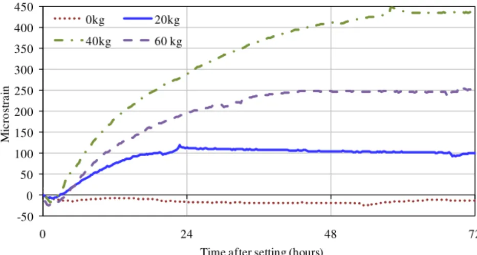
Three prisms of each system were monitored under sealed condition, and Figure 2 presents the average expansion strain curves measured for each expansive concrete and reference concrete. Each curve is identified according to the quantity of CSA additive used in a cubic meter of ccrete. Figure 3 presents the same information for the Power CSA mixtures. It is seen that the on-set of expansion occurred at about 3 hours after on-setting, and that significant expansion of up to 450 με in 3 days for the regular CSA additive and up to 4400 με in 6 days for Power CSA addi-tive. It is also observed that the expansion increased with the amount of expansive additive used, except for the dosage rate of 60 kg/m3 of the regular CSA additive (Fig. 2), which did not perform as well as the 40 kg/m3 mix. It is hypothesized that the 60 kg/m3 CSA mix developed too many microcracks, which impaired the transmission of expansive forces in the system, as discussed by Morioka et al. (2003).
Thermocouples C150x12 steel base 12‐mm foam rubber LVDT LVDT Steel mould Concrete sample (75x75x295 mm) 1.5‐mm foam rubber lining Bearing assembly 3 Sealed surface 2
Despite the large quantity of CSA additive used in the concrete mixes (with some dosage rates exceeding the manufacturer’s recommendations), the expansions were not large enough to produce macrocracks. For instance, the most successful expansive concrete tested in this study developed free expansion of 0.44% after 6 days, without any visible signs of cracking. Howev-er, observations under the electron microscope revealed many microcracks in this specimen. Et-tringite was also observed throughout the system, indicating a high Al/S environment as would be expected in a CSA system. Nevertheless, it was concluded that this approach did not provide the desired crack pattern (i.e. large random cracks).
Figure 2. Expansion of CSA expansive concrete prisms measured over 3 days. -50 0 50 100 150 200 250 300 350 400 450 0 24 48 7 M icr o st rai n
Time after setting (hours)
2
0kg 20kg
40kg 60 kg
Figure 3. Expansion of Power CSA expansive concrete prisms measured over 6 days.
0 500 1000 1500 2000 2500 3000 3500 4000 4500 0 24 48 72 96 120 Mi c ro st ra in
Time after setting (hours)
144 20kg (PCSA) 40kg (PCSA) 60kg (PCSA) a b 3
6th Intl Conference on Concrete Under Severe Conditions Environment and Loading, Merida, Mexico, June 7-9, 2010
Figure 4. Microcracks in CSA specimen at 1000x magnification (a), and ettringite crystals in cavity of
mixture of water, OPC and CSA additive (proportions of 0.5:1:1 by mass), respectively. Large table and aligned
& re expansive cement presents the maximum pe prod n t ders by the different blends. T rtions rviou ncrete a xpansive cement pastes (kg).
OPC CSA Agg gate
same system at 10,000x magnification (b).
2.2 2nd preliminary approach: Normal concrete with drilled holes filled with expansive paste
In order to delay the expansion to a time when the concrete matrix is more brittle and suscepti-ble to cracking, a second approach was considered. The three old control prisms (without CSA additive) tested in the previous experiment were cut to make nine cubes for additional testing. Cylindrical holes (diameter of 10 mm) were drilled part way through the cubes using different alignment patterns. The drilled holes were then filled with expansive cement paste made of a cracks developed in the cubes within 1 day, but the crack pattern was predic
with the patterns of holes, and thus not representative of typical AAR crack patterns. 2.3 Selected approach: Pervious concrete filled with expansive cement paste
A third approach was developed by combining pervious concrete and expansive cement paste. Typically, pervious concrete has no fine aggregate and has just enough cement paste to coat the coarse aggregate particles while preserving the interconnectivity of the large voids. Pervious concrete is normally used for flatwork applications (like parking areas) allowing rain water to pass directly through, thereby reducing runoff from a site.
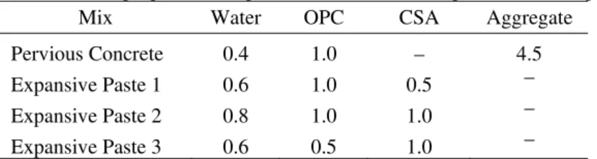
In a first step, pervious concrete was prepared to cast cylinders (100 x 200 mm) using the mix formulation proposed by Wang et al. (2006). The proportions were 0.4:1.0:4.5 for water, OPC, and coarse aggregate (Table 1). Two sieved sizes of coarse aggregate were tried separately: a finer size from 6.3 to 12.5 mm (A), and a coarser size from 12.5 to 25.0 mm (B). Wet curing was applied for 3 days. Volume measurements of the pervious concrete voids by the water dis-placement method revealed 32% voids when using Aggregate A, and 34% voids with Aggregate B, and both aggregates displayed good adherence to the paste. Twenty-four hours after casting, the outer surface of each cylinder was coated with a thin layer of ordinary mortar with mass proportions of 0.6:1:2 for water, OPC and sand, respectively. The top and bottom surfaces were left opened to provide an opening to introduce the expansive paste into the pervious concrete when fully cured. The coated surfaces of the cylinders were smoothed to easily track the forma-tion of cracks over time, and the cylinders were returned back to the curing room.
The next step was to fill the voids of the pervious concrete cylinders with expansive cement paste, which is expected to expand around the coarse aggregate, inducing internal forces in all directions within the pervious concrete. The expansive paste swelling around the aggregate is close to what actually happens in AAR-affected concrete, where the gel produced by the reac-tion forms around the aggregate and expands further when in contact with moisture (Newman Choo 2003). Different blends of OPC and CSA additive were used to prepa
pastes (Table 1) in order to op e th nsi e pervious concrete. Table 2 crack o timiz nings e expa uced o on within th he test cylin able 1. Mass propo of pe s co nd e
Mix Water re Pervious Concrete 0.4 1.0 – 4.5 – Expansive Paste 1 0.6 1.0 0.5 Expansive Paste 2 0.8 1.0 1.0 – – Expansive Paste 3 0.6 0.5 1.0
T aximu ack ngs sure test c ders ( .
Age / Mix 1A 1B 2A 2B 3A 3B
able 2. M m cr openi mea d on ylin mm)
24 hours 1.4 1.0 no no 0.3 0.1
48 hours 5.0 5.0 6.0 7.0 4.0 6.0
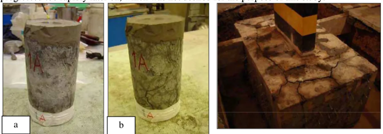
Expansive Paste 1 provided the most desired resu random cracks developing rapidly (Fig. 5a & 5b), cracks found in affected reinforced concrete foundatio and loading conditions. In Expansive Paste 2, fo progressed too rapidly later on, which was not
Figure 5. Pervious concrete cylinder 1A at 6 hrs (a) Figure 6. AAR-affected concrete lts, with considerable free expansion and large
which are similar to typical AAR-induced ns (Fig. 6), despite their different restraint r instance, the crack formation was delayed and desired for the purpose of this study.
lts, with considerable free expansion and large which are similar to typical AAR-induced ns (Fig. 6), despite their different restraint r instance, the crack formation was delayed and desired for the purpose of this study.
and 24 hours (b) after application of expansive paste. and 24 hours (b) after application of expansive paste.
b
5 Expansive Paste 1 provided the most desired resu
random cracks developing rapidly (Fig. 5a & 5b), cracks found in affected reinforced concrete foundatio and loading conditions. In Expansive Paste 2, fo progressed too rapidly later on, which was not
Figure 5. Pervious concrete cylinder 1A at 6 hrs (a) Figure 6. AAR-affected concrete b
a
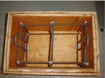
build-rm was designed with double wood panels (Fig. 7) so that a mortar layer could easily be cast later over the side and bottom surfaces of the large pervious concrete prism (Fig. 8), which was done one day after casting the pervious concrete. A 20-mm steel tamping rod was used to compact the mortar. Moist curing with wet burlap was applied for 2 days, after which time the expansive cement paste was introduced, which had a formulation identical to Paste 1 in Table 1.
ing foundation (Andrade 2006).
3 EXPERIMENTAL VALIDATION OF SELECTED SIMULATION APPROACH
The shape of the concrete specimen used for this part of the study was chosen to represent small building foundations and had overall dimensions of 600 x 400 x 400 mm. The concrete prism was slightly reinforced using 10-mm bars with a 40-mm concrete cover (Fig. 7). The pervious concrete formulation shown in Table 1 was used. Aggregate B with a size ranging from 13 to 25 mm was chosen for the larger voids created in pervious concrete in order to allow easier intro-duction of the expansive paste into the voids of the pervious concrete, which achieved a 28-day compressive strength of 7 MPa (which is typical of commercial pervious concrete).
The prismatic fo
6th Intl Conference on Concrete Under Severe Conditions Environment and Loading, Merida, Mexico, June 7-9, 2010
Figure 7. Double-panel wooden form used to cast reinforced pervious concrete prism.
Figure 8. Casting of external mortar layer on sides and bottom of pervious concrete prism.
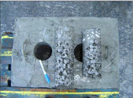
Since the bottom surface of the concrete prism was sealed with the mortar layer, six drain holes were drilled through the mortar layer near the bottom of the concrete prism. This was done to al-low trapped air to escape and the expansive paste to fal-low easily without resistance and to con-firm the flow of the paste from the top to the bottom of the prism. On the first trial, the paste did not flow down to the bottom surface of the prism. To solve this problem, two vertical cores of 100 mm diameter and 300 mm height were drilled in the prism, confirming that the paste had filled only the top 100 mm of the prism (Fig. 9). The drilled holes were then filled with addi-tional expansive paste and a portable vibrator was used to induce energy to the paste making it more fluid during the placement (Fig. 10). Expansive cement paste was added to the two large x small drains, confirming the success of the oper-ed with rubber stoppers.
openings until it started to flow through the si ation. The small drain holes were then plugg
Figure 9. Cores extracted from concrete prism.
Fig 10. Expansive paste poured through drilled holes.
During the fabrication of a second prism, two cylindrical shapes (e.g. 100 x 200 mm cylindrical moulds) were secured to the reinforcing steel cage before casting the pervious concrete into the prismatic form to provide openings so that holes would not need to be drilled later. After one day, when the pervious concrete was sufficiently hard, the two plastic moulds were removed from the pervious concrete prism. The two empty cylindrical holes were then used for the placement of the expansive cement paste and to introduce the portable vibrator in order to im-prove the flow of the expansive paste into the voids of the pervious concrete. Finally, two 100 x 200 mm cylinders of pervious concrete, which had been cast when the large prism was made, were used to fill the openings after the placement of the expansive paste in order to prevent high concentrations of expansive paste at these two locations.
k served. The obtained crack pattern was very similar to typical crack patterns observed in AAR-affected concrete foundations. For example, Figure 11a presents the simulated expansion and
ure
Within 24 hours after the application of the CSA expansive paste, the prism started to crac severely and expanded for three additional days, after which time no more new cracks were
6th Intl Conference on Concrete Under Severe Conditions Environment and Loading, Merida, Mexico, June 7-9, 2010
cracking on the laboratory prism, and Figure 11b illustrates an existing concrete building foun-dation affected by AAR in Brazil (Andrade 2006).
ccelerated experi-mental simulation of the expansion and random surface cracking typically found in concrete
i aggregate reaction. This accelerated laboratory simulation will be a structural health monitoring strategy for AAR-affected concrete
• The OPC concrete specimens with drilled holes filled with expansive paste displayed severe cracking, but the crack pattern was different from AAR-induced cracks.
approach consists of casting a pervious concrete specimen, in a first step, and
•
AR. It is designed to simulate the resulting surface deterioration.
s
FA co
Figure 11. (a) Simulated cracking in lab prism; (b) AAR-affected building foundation (Andrade 2006).
a b
4 CONCLUSIONS
The main objective of the study presented in this paper was to develop an a structures affected by alkal
eventually used to develop
building foundations, with the aim to provide timely information for maintenance and rehabili-tation planning and to ensure the safety of AAR-affected structures and their occupants.
Different simulation approaches were evaluated and, from the obtained results, the following conclusions can be drawn:
• The expansive concrete specimens made with blends of OPC and CSA additive produced considerable expansion, but did not form large cracks (only fine microcracks), even for large CSA additive dosage rates.
expansion and • The proposed
filling the large voids with expansive cement paste, in a second step. This approach was found successful when tested on small cylindrical specimens and large-size prismatic rein-forced concrete specimens, with crack openings and patterns that are very similar to those found in existing AAR-affected reinforced concrete building foundations.
The proposed approach, however, does not simulate or accelerate any internal chemical reac-tion of A
A NTS
ucted thi CKNOWLEDGME
The first author, who is a Ph.D. candidate with Sao Paulo University in Brazil, cond
research work during his stay as an invited guest researcher at the National Research Council (NRC) in Ottawa, Canada, from April 1st, 2009 to March 31, 2010, with financial support from PESP (Fundação de Amparo à Pesquisa do Estado de São Paulo) and NRC. The authors would like to acknowledge the contributions of Mr. Tiberio Andrade, who is an engineering nsultant in Brazil, Mr. Ted Hoogeveen of NRC for his technical support, and Denka Corpora-tion for supplying the expansive calcium sulphoaluminate additive.
9
5B
REFERENCES
Andrade, T. 2006. Historico de casos de RAA ocorridos recentemente em fundacoes de edficios na regiao metropolitana de recife. II Simposio sobre reacao alcali-agregado em estruturas de concreto. Sao Paulo-SP, Brazil. IBRACON.
Cusson, D.; Hoogeveen, T. 2007. New Test Method for Determining Coefficient of Thermal Expansion at Ear-ly Age in High-Performance Concrete. 12th International Conference on Chemistry of Cement. Montreal. Canada.
Fournier, B.; Ideker, J.H.; Folliard, K.J.; Thomas, M.D.A.; Nkinamubanzi, P.C. & Chevrier, R. 2009. Effect of environmental conditions on expansion in concrete due to alkali-silica reaction (ASR). Material
characteri-zation 60: 669-679.
Morioka, M., Sakai, E. & Daimon, M. 2003. Influence of Preparation Method on Performance of Expansive Additive Containing Free-lime, Hauyne and Anhydrite, Concrete Research and Technology, 14(2), 43-50. Newman, J. & Choo, B.S. 2003. Advanced Concrete Technology. Burlington. Elsevier: 13/1-13/37.
Nery, G.; Cusson, D. & Helene, P. 2010. Development of a remote monitoring strategy for concrete building foundations affected by alkali-aggregate reaction. Sixth International Conference on Concrete under Severe
Conditions Environment and Loading. Merida, Mexico.
Wang, K.; Schaefer, V.R.; Kevern, J.T. & Suleiman, M.T. 2006. Development of mix proportion for functional and durable pervious concrete. NRMCA Concrete Technology Forum: Focus on pervious concrete. NRMC. Toma, I.O.; Miki, T.; Niwa, J. 2007. Steel fibers as a tool to improve shear carrying capacity of RC beams with
random cracks. Concrete under severe condition: Environment & loading. Laboratoire central des ponts et chaussées. Tours, France: 777-786.