HAL Id: in2p3-00711773
http://hal.in2p3.fr/in2p3-00711773
Submitted on 25 Jun 2012HAL is a multi-disciplinary open access archive for the deposit and dissemination of sci-entific research documents, whether they are pub-lished or not. The documents may come from teaching and research institutions in France or abroad, or from public or private research centers.
L’archive ouverte pluridisciplinaire HAL, est destinée au dépôt et à la diffusion de documents scientifiques de niveau recherche, publiés ou non, émanant des établissements d’enseignement et de recherche français ou étrangers, des laboratoires publics ou privés.
Report on the detection and acquisition systems at NFS
X. Ledoux, E. Bauge, G. Belier, T. Caillaud, A. Chatillon, T. Granier, O.
Landoas, J. Taïeb, B. Rossé, I. Thfoin, et al.
To cite this version:
X. Ledoux, E. Bauge, G. Belier, T. Caillaud, A. Chatillon, et al.. Report on the detection and acquisition systems at NFS. 2012, pp.39. �in2p3-00711773�
Report on the detection and acquisition systems at NFS
The NFS collaboration
3
Table des matières
The NFS Facility ... 7
1 Introduction ... 7
2 NFS description ... 7
3 Neutron beam monitoring ... 10
4 Physics case ... 11
The Medley facility ... 13
The CARMEN detector ... 19
1 Introduction ... 19
2 Detector characteristics ... 19
3 The use at NFS ... 21
The GAINS set-up ... 25
FALSTAFF ... 27
Active targets based on liquid scintillator ... 31
1 Introduction ... 31
2 Description of the active target ... 31
3 Conclusions ... 34
Conclusion ... 35
Letters Of Intents for Day-One experiment at NFS ... 37
5
This report is a compilation of the studies performed by several teams belonging to the NFS collaboration for the use of different experimental set-ups at the Neutrons For Science facility. The list of the set-ups presented here is not exhaustive and covers only a small part of the set-ups usable at NFS. These set-ups will be used in the experiments described in the Letters Of Intent for Day One experiment submitted to the Scientific Advisory Committee of SPIRAL-2.
7
The NFS Facility
1 Introduction
The “Neutrons For Science” (NFS) facility will be a component of the future SPIRAL-2 facility, dedicated to the production of very intense radioactive ion beams, under construction at GANIL in Caen (France). The SPIRAL-2 facility is based on a high intensity linear accelerator (LINAG) that is designed to induce fission in the SPIRAL-2 production target. The use of intense LINAG beams will also be used in two experimental areas, the S3 spectrometer and the neutron beam-line NFS. The neutrons of the NFS facility are produced out of the reaction of the LINAG deuteron or proton beams with dedicated converters. NFS will be composed of a pulsed neutron beam for in-flight measurements and irradiation stations for cross-section measurements and material studies. Continuous and quasi-monokinetic energy spectra will be available, respectively produced by the interaction of deuteron beam on a thick Be converter and by 7Li(p,n) reaction on a thin converter. The flux at NFS will be up to 2 orders of magnitude higher than those of other existing time-of-flight facilities in the 1 MeV - 40 MeV range. NFS will be a very powerful tool for physics, fundamental research as well as applications like the transmutation of nuclear waste, design of future fission and fusion reactors, nuclear medicine or test and development of new detectors.
2 NFS description
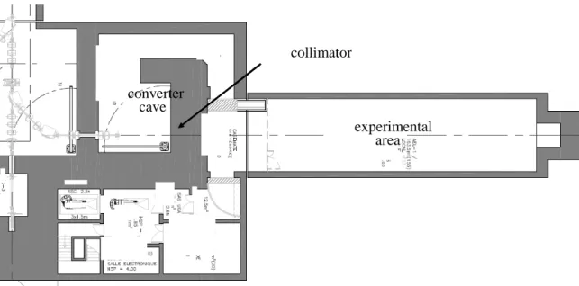
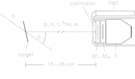
NFS is mainly composed of two rooms: a converter cave and an experimental area separated by a 3 meter-thick wall of concrete (see Figure 1). The converter room includes the primary ion beam extension, the converter to produce neutrons as well as the irradiation set-ups. A bending magnet is placed between the converter and the collimator entrance to clean the neutron beam from protons, when a thin converter is used (see following section). Neutrons in the 0° direction are guided to the experimental room through a collimator consisting of iron and polyethylene.
The experimental area (30 m x 6 m) will allow performing measurements by using large experimental set-ups at desired distances from 5 m up to 25 m away from the converter point. This flexibility is very interesting in terms of flux and energy measurement resolution. The experimental area is designed for the use of radioactive samples up to 10 and 1 GBq for sealed and non-sealed samples, respectively.
In addition, the ion beam-line in the converter cave will be equipped with an irradiation box for cross-section measurements of proton and deuteron induced reactions by the activation technique. The use of light ions, up to carbon, is also envisaged to irradiate samples for material studies.
8
Figure 1 : Schematic view of the NFS facility
Two production modes will be used with the pulsed proton and deuteron beams delivered by the LINAG.
First, the deuteron break-up reaction on a thick converter made of carbon or beryllium generates neutrons with a continuous energy distribution. At 0 degree, the spectrum extends up to 40 MeV with an averaged value of approximately 14 MeV as shown in Figure 2 left panel.
Figure 2 : Neutrons energy distribution at 0 degree produced by deuteron break-up
reaction on thick converters [1][2] (left panel) and by the 7Li(p,n)7Be reaction on a thin lithium target [3] (right panel).
Second, the 7Li(p,n)7Be reaction on a thin lithium converter (1 to 3 mm of thickness) produces nearly mono-energetic neutrons as shown in Figure 2 right panel. In this case, the neutron spectrum at 0° shows a mono-energetic peak due to the 7Li(p,n) reaction process, with a continuum tail attributed to the break-up process. The contribution of the continuum depends on the target thickness and on the proton energy. It can be removed from time-of-flight measurement. The protons which did not react in the converter are swept out of the
collimator converter cave experimental area collimator converter cave experimental area
9
neutron beam line with a bending magnet placed downstream of the target and guided toward a beam-dump.
The neutron energy measurement resolution is of prime interest for a time-of-flight facility. The time-of-flight (TOF) is measured with a Time to Digital Converter (TDC) between the trigger of the detector and a time signal delivered by the LINAG (ESCF). Flight-path and beam-time characteristics are the key parameters for the TOF technique. Taking into account the beam transport to the converter, a burst duration shorter than 1 ns is guaranteed. Taking into account a 30 m flight path and variable time resolution of different detectors, the expected resolution of the energy measurement of the impinging neutrons is given in Figure 3. It may be observed that with fast detectors the energy resolution at 40 MeV is better than 1 % and even for slow detectors like, High Purity Germanium detector (∆t ≈ 8 ns), the energy resolution remains better than 5%.
Figure 3 : Energy resolution as a function of the neutron energy and the detection time-resolution ∆∆∆∆t.
The LINAG beam frequency (88 MHz) is too high to allow for time-of-flight measurements in the considered neutron energy. In order to avoid wraparound effects, the neutron beam frequency must be reduced to a value depending on the flight path and the low energy part of the spectra. In any case it must be lower than 1 MHz. Therefore a fast beam-chopper will select one over N bursts, with N>100. As a consequence the maximum ion-beam intensity in the converter cave is 50 µA, which corresponds to a maximum power deposition in the Be converter of 2 kW.
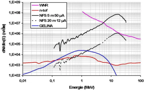
By taking into account the neutron yield production[1], the beam division and the flight path, the neutron flux can be evaluated and compared to other major time-of-flight facilities, namely n_TOF at CERN, WNR at Los Alamos (where neutrons are produced in a spallation reaction) and GELINA in Geel (where neutrons are produced by photo-fission). The length of the TOF area allows either high-intensity flux (path distance 5 m) or high-resolution (path distance 20 m) measurements. We can see in Figure 4 that NFS is very competitive in terms of average flux in comparison with n_TOF, GELINA or WNR between 1 and 35 MeV. It has
10
to be stressed that this is achieved mainly due to the high repetition rate, compared to the other facilities.
Figure 4: Neutron flux at NFS for two flight paths compared to three other neutron time-of-flight facilities.
Moreover, in comparison to other neutron facilities, NFS shows some advantages relative to the neutron production mechanism itself. In spallation sources the high energy neutrons (up to hundreds MeV), may imply challenges for both collimation and background. In addition, the gamma-flash originating from the interaction of the charged primary beam (proton, electron) into the neutron-production target, which is known to be very penalizing, especially because it induces a dead time, will be probably strongly reduced at NFS. Note that high energy gammas are produced by π0 decay in spallation sources and by bremsstrahlung in photo-neutron sources based on electron accelerators.
3 Neutron beam monitoring
The neutron flux will be characterized in intensity and energy with two monitoring systems. Upstream, a micromegas detector will be placed just after the collimator, and downstream the experimental set-up a fission chamber will be used. The micromegas detector does not disturb the neutron flux and therefore can be used during the different measurements, so that on-line information on the neutron flux can be a part of the experiment data flow. The fission chamber placed downstream will also be used in-beam to get a crosscheck information.
The measurement of the neutron energy relies on the time-of-flight measurement, between the neutron production (converter) and its detection. Consequently, a time-of-flight measurement electronics and data acquisition has to be installed, treating a time signal coming from the accelerator and a time signal of the monitoring detector. This ensemble of
11
electronics and detection will be a permanent contribution to the various experimental set-ups that the NFS facility will host.
This ensemble of detectors will be first used in a commissioning phase to characterize the beam properties in energy and intensity. In addition, during this phase, a profile of the beam will be realized with a simple set-up; a small plastic detector will be moved in a plane perpendicular to the neutron beam direction in order to measure a spatial description of the beam intensity.
4 Physics case
Neutron-induced reactions in the NFS energy range play an important role in various applications like reactors of the new generation, nuclear medicine, Single Event Upset (SEU) appearing in electronics devices, fusion technology, or the development of nuclear model codes in general. Only very limited data exist for neutron induced reactions above 14 MeV and for many cases both fission and (n,xn) reaction cross sections are unknown. The above energy range corresponds also to the opening of new reaction channels like (n,p), (n,α), allowing the pre-equilibrium model studies, i.e. the transition between low (compound nucleus formation via capture) and high energy models (intra-nuclear cascade). The NFS characteristics are particularly well suited for studying these reactions as well as deuteron and proton induced reactions.
The (n,xn) reaction cross sections can be measured at NFS by three different methods, namely the direct detection of neutrons, the prompt gamma-ray spectroscopy of the reaction residues, or the activation technique, based on the decay spectroscopy of the reaction residues. The beam properties (energy and resolution) will allow a precise measurement of the cross-section excitation functions, from the threshold up to the maximum of cross-section for (n,2n), (n,3n) and (n,4n) reactions, where data are either unknown or known with only very bad accuracy.
Double-differential cross-sections measurement for neutron-induced light-ion production (p, d and alpha particles) will also be performed. Actually, the light-ion production knowledge is essential in medical and electronic applications for accurate dose evaluation and for gas production prediction in windows or targets of several nuclear constructions. These studies are also fundamental to understand the process of pre-equilibrium emission, responsible for fusion hindrance appearing at energies above the Coulomb.
The study of fission will be an important part of the NFS physics case. Actually, the probable development of innovative fast nuclear reactors requires new high quality data for a large set of fissioning systems (from thorium to curium) for an energy range going from thermal up to the fast (~2 MeV) energy domain. Complementary to reaction cross-section data, the mass and charge distributions are needed with a high precision for burn-up calculations of the reactor fuel, because they are directly connected to the control and the safety of the reactor. A good knowledge of the cross sections is necessary for assessing the neutron balance or to predict radioactive waste inventories. The neutron multiplicity distributions as well as the energy released by gamma emission are also required.
Proton and deuteron induced activation reactions are of great interest for the assessment of induced radioactivities in accelerator components, targets and beam stoppers and are important for isotope production for medical purposes. The cross sections are needed in the
12
energy range from the threshold of the activation reactions (2 - 10 MeV) up to 40 MeV for both incident ions. Present status of the measured and evaluated data needs urgent and strong improvement. The measurement of excitation functions can be performed at NFS in an energy domain (20-40 MeV) where data are not existing or known with poor accuracy. In frame of the ”Day-One” program of starting investigations (LoI Phase 1 - NFS), a development of the reaction chamber hardware incorporated with pneumatic sample transport system is under way within the NPI Řež and KIT Karlsruhe collaboration.
The following sections are dedicated to a detailed description of some of the foreseen experimental set-ups.
References
[1] M. J. Saltmarsh et al., NIMA145 (1977) p81-90
[2] J. P. Meulders et al., Phys. Med. Biol. (1975)vol 20 n°2, p235 [3] C. J. Batty et al., NIM 68 (1969) p273-276
[4] A. Takibayev, CEA/Saclay, Internal Report Irfu 11-75 (2011)
[5] M. Majerle and S. Simakov, Karlsruher Institut für Technologie, Internal report, INR-Nr. 15/10 FUSION Nr. 368 (2010)
The Medley facility
C. Gustavsson, S.Pomp, M. Lantz, A. Solders, M. Österlund Department of physics and astronomy, Uppsala University, Sweden
F.-R. Lecolley LPC Caen, France U. Tippawan
Chiang Mai University, Thailand Y. Watanabe
Kyushu University, Japan
Despite longstanding measurement efforts, the demand of high quality nuclear data has in recent years even increased. Among the applications with the highest demands one can mention cancer therapy and dosimetry, energy production and single-event effects in electronics. We propose measuring double-differential cross sections for neutron-induced light-ion production (p, d and alpha particles) at NFS, using the Medley detector which has been used for similar experiments in Uppsala. We also plan to upgrade the Medley facility for measuring fission fragment angular distribution and fission cross section on an absolute scale, i.e. versus the np cross section. Experimental studies of fission induced by high-energy neutrons are needed for both improving our theoretical understanding of the fission process, and for many applications. In addition, neutron-induced fission of 238U is the most widely used standard for monitoring high-energy neutron beams, and it is used at many high-energy neutron facilities.
The Medley facility, currently installed at the neutron beam of The Svedberg Laboratory (TSL), Uppsala, Sweden is described in a number of publications, the most relevant ones are listed below as Refs. [6][13]. Schematic layouts of the chamber and telescope as well as some photographs are shown below in Figure 5 to Figure 9.
The facility has been used for measurements of neutron-induced light ion production and elastic np and nd scattering over a wide energy range. Recently Medley has been used to measure the neutron spectrum of the ANITA white neutron beam at TSL from the highest energies around 180 MeV down to about 1 MeV. Besides the local group from Uppsala University, the main collaboration partners over the past years have been LPC Caen, France, Chiang Mai University, Thailand, and Kyushu University, Japan.
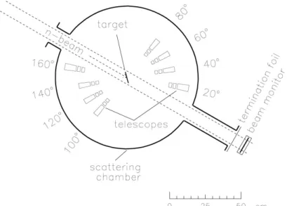
Medley is designed for detection of charged particles over a wide dynamic range. It consists of eight three-element telescopes mounted inside a 240 mm high cylindrical
14
evacuated chamber with inner diameter of 800 mm. Eight telescopes are placed at 20° intervals, covering scattering angles from 20° to 160° simultaneously. The telescopes are usually mounted in two sets, one on each side of the beam, covering the forward and backward hemispheres, respectively. All the telescopes are mounted onto a turnable plate at the bottom of the chamber and, therefore, measurements can in principle be made at any angle. The chamber is equipped with a pump to reach pressures of about 10-5 mbar. Thus, the stopping power of the remaining air in the chamber is negligible. Thus, even alpha particles with lowest energy do not loose a measureable amount of energy on their way from the production target to the detector.
Each telescope consists of two fully depleted ∆E silicon surface barrier detectors (SSBD) and a CsI(Tl) crystal. The thicknesses of the first eight ∆E detectors (∆E1) range between 50
and 60 µm. For the second one (∆E2) two detector sets are available. In the thinner setup,
thicknesses range between 400 and 500 µm. In addition a group of ∆E2 detectors with
thicknesses around 1000 µm is available. These SSBDs are all 23.9 mm in diameter (nominal). The last part of each telescope contains a CsI(Tl) detector to fully stop the detected particles. Two sets of CsI(Tl) detectors are available. One where the crystals are 50 mm long and have a diameter of 40 mm, and another with crystals measuring 50 mm in diameter and a 100 mm in length. The back-end part of the crystals, 20 mm and 30 mm long, respectively, has a conical shape, tapering off to 18 mm diameter, to fit the size of a read-out diode. The read-out diode is Hamamatsu S3204-08 and measures 18 x 18 mm2.
To obtain a well-defined acceptance, a plastic scintillator collimator can be placed in front of each telescope. A conventional collimator can cause problems like in-scattering or particle reactions before reaching the first detector. To avoid such complications, the plastic scintillator can be used as an active anti-coincidence collimator to discard the signals from particles that did not pass straight into the first detector. The plastic scintillator collimators have a 40 × 40 mm2 square shape, with a 19 mm diameter hole at the center and a thickness of 1 mm (see Figure 7). The scintillators are read-out with photomultiplier tubes (PMT) from Hamamatsu, small enough to fit into the chamber. These PMT have been modified to be operational directly after reaching the operational pressure in the Medley chamber. The scintillators thickness is sufficient also for the most penetrating protons to produce a reasonable pulse height. Since energies at NFS are much lower, the minimum signal height would be larger than the minimum signals at TSL. Thus, the collimators could probably be used passively.
For the planned experiments at NFS, we consider adding 25 µm SSBDs for better discrimination between alpha particles and fission fragments. We furthermore work on a design for a central detector and target system for fission measurements. The system will consist of a 238U-CH2-target surrounded by 2 parallel-plate avalanche counters (PPAC). One
of these PPAC would be optimized for registering fission fragments, the other for detecting of forward scattered protons from elastic np scattering. Such a solution would allow Medley to work with the white neutron beam and still achieve good neutron energy resolution from time-of-flight measurements. Figure 10 shows the intended design of the upgraded Medely detector.
15
After passing the custom-made pre-amplifiers, the detector signals are read-out using standard electronic in NIM crates. The energy signals are amplified using Dual Amplifiers by ORTEC (Dual Spec Amp 855). These amplifiers can be considered a part of the Medley chamber. At TSL, the data-acquisition was achieved using the SVEDAQ system which is rather complex and un-stable. For NFS, use of the GANIL DAQ system is planned. This will minimize the dead time and allow for careful offline analysis of the pulse shapes, etc.
Figure 5: Schematic layout of the detector arrangement in the Medley chamber. See text.
Figure 6: Photograph of the chamber. Not seen is the mounting and the arrangement of the vacuum pumps. The table on which the telescope rails are mounted
can be rotated freely from the outside. The individual telescopes are mounted on rails and can be moved along these rails to the desired distance from the target. When closed,
16
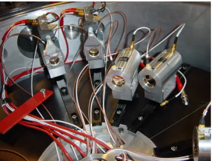
Figure 7: In this photograph a sample arrangement of four telescopes can be seen. In this case the telescopes contain the small CsI detectors. The two telescopes on the left side carry the active collimator scintillators while in the two telescopes on the right side
the front of the first Si detector can be seen.
Figure 8: Three target frames are mounted on the lock of the Medley chamber. The frames can be moved from the outside. Thus, targets can be changed will the vacuum
17
Figure 9: Schematic drawing of the layout of one telescope. The drawing shows the smaller housings with the shorter CsI detectors.
Figure 10 : Left: Schematic layout of the detector arrangement in the Medley chamber. (Not to scale.) In the overview sketch in the upper right corner the beam
enters from above. The telescopes are placed on either side of the beam covering backward and forward scattering angles respectively. In the chamber centre sits the two-layered target, with one PPAC detector on either side (see the detailed picture at the
18 References
[6] S. Dangtip, et al., Nucl. Instr. Meth. Phys. Res. A 452, 484 (2000).
[7] U. Tippawan, et al., Phys. Rev. C 69, 064609 (2004) and Phys. Rev. C 73, 039902(E) (2006).
[8] U. Tippawan, Ph.D. thesis, Chiang Mai University, 2004, online:
http://library.cmu.ac.th/digital_collection/etheses/. [9] V. Blideanu, et al., Phys. Rev. C 70, 014607 (2004). [10] U. Tippawan, et al., Phys. Rev. C 73, 034611 (2006). [11] U. Tippawan, et al., Phys. Rev. C 79, 064611 (2009).
[12] Y. Naitou, et al., Proceedings of the 2009 Annual Symposium on Nuclear Data, Nov. 26-27, Ricotti, Tokai, Japan (2009)
[13] R. Bevilacqua, et al., Nucl. Instr. Meth. Phys. Res. A 646, 100 (2011).
The CARMEN detector
X. Ledoux, G. Bélier, M. Dupuis, C. Varignon CEA, DAM, DIF F-91297 Arpajon
1 Introduction
The 4 π neutron detectors, often called “neutron balls” have been used for more than 50 years. The main advantage is the very high neutron detection efficiency. The development of such detector allowed measuring the fission neutron multiplicity distribution [15] and not only the average value as it was limited before. Several detectors were developed loaded with cadmium or gadolinium in order to study reactions where several neutrons are emitted. In addition to the fission neutron multiplicity [16], these detectors were intensively used for (n,xn) cross-sections measurement [18][19]. There are also some examples of use for capture cross-section measurements [17]. Several neutrons balls were also developed for the study of hot nuclei in reactions induced by heavy ion [22][23], light charged particle [24] or antiproton[25]. Actually, the absence of coulomb barrier makes the neutron a very efficient probe of nucleus excitation energy. In particular, the neutron multiplicity is a very powerful tool for the hot nuclei study. Therefore several neutrons balls were developed for experiments the study. In the eighties, the renew interest in the study of spallation reactions open a new use to the neutron ball[26][27]. The 4 π neutron detectors were used in with thin and thick targets, in this case liquid with very low gadolinium concentration were needed in order to measure multiplicity up to 200.
All these examples show how the large 4π neutrons detectors are a powerful tool. We have build such a detector to study (n,xn) reactions as well as fission process. A particular attention was paid to the high efficiency of this detector. Note that such set-up requires dedicated beam conditions especially with neutron induced reactions.
2 Detector characteristics 2.1 Description
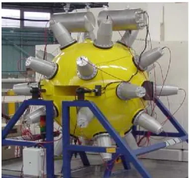
CARMEN (Cells Arrangement Relative to the Measurement of Neutrons) is a large spherical neutron detector of high efficiency. It consists of two independent vertical hemispheres, 60 cm in outer-radius, 15 cm in inner-radius, each one filled with less than 0.5 m3 of BC521 liquid scintillator provided by Bicron. This scintillator is composed of 1-2-4-trimethylbenzene loaded with 0.5 % of gadolinium. A spherical area in the centre of the detector allows placing the sample. The two hemispheres can be moved perpendicularly to the beam direction in order to perform double differential cross sections measurements. The 15 cm in radius area at the centre of the detector defines the reaction chamber. A horizontal cylindrical channel, 5 cm in radius, allows the neutron to reach the reaction chamber, the
20
beam exit being ensured by a rectangular wide-mouthed channel. Twelve phototubes (XP4512 of five inches in diameter provided by photonis) surrounding each hemisphere collect the light produced in the scintillator. Each phototube is immerged in the liquid in order to increase the light collection efficiency. Approximately 4.5% of the external sphere surface is covered by the phototubes allowing direct and reflected light collection. Each hemisphere is supported by 2 frames moving on rails. Due to the toxicity and flammability of the sinctillator, a retention tank is placed under each hemisphere.
Figure 11 : Picture of the CARMEN detector.
2.2 Detection process
CARMEN measures the neutron multiplicity event by event allowing determining the neutron multiplicity distribution of a reaction. The neutron detection process generates two signals, a prompt one in the first hundredth of nanoseconds following the reaction and a delayed one which can occur up to 50 µs later. The first one is due to the scattering of neutron on the hydrogen nuclei. The energy lost by the proton recoil produces light detected by the phototubes. The prompt peak can also be generated by gamma emitted in the studied reaction. The prompt signal being generated by all the neutrons and the gamma emitted, its intensity is related to the violence of the reaction.
The neutron then slows down by loosing its energy by inelastic and mainly elastic scattering on hydrogen and carbon nuclei until leaving the detector or being captured. In the thermal energy region, the neutron can be captured by a gadolinium nucleus thanks to the high capture cross-sections (100000 and 250000 barns for isotopes 155 and 157 respectively). The gadolinium nucleus de-excites by the emission of gamma rays, three on average per capture for a total energy around 8 MeV. Gamma rays interact by Compton effect with electrons whose recoil produces light. This signal is called delayed because due to the low gadolinium concentration, 0,5 % by weight, more than 99% of the neutrons are captured in
21
the 50 µs following the prompt signal. The neutron capture on hydrogen is also possible, in that case a 2.2 MeV gamma ray is produced. Due to the statistical nature of neutron moderation, the simultaneously generated neutrons produces delayed pulsed separated in time. The neutron multiplicity is deduced by delayed signals counting in a 50µs long gate. The detector can be used as slave with an external trigger or in some cases the prompt signal can be used to trig the neutron counting. For each event, two 50 µs gates signal (separated by 50 µs) are generated to measure the neutron and the background multiplicities respectively. The neutron detection efficiency of CARMEN is very high, 85% for evaporation fission neutrons, but CARMEN is also very sensitive to the neutron and gamma ray background.
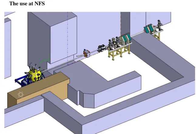
3 The use at NFS
Figure 12: View of the CARMEN detector in the NFS facility.
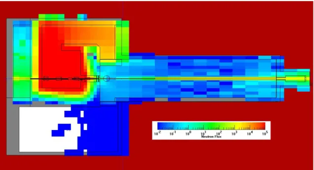
Due to its high efficiency, CARMEN is very sensitive to the neutron background and a particular attention was paid about that. The main sources of neutron background in the time-of-flight area have been clearly identified. They are linked to the neutron beam for the neutron collimator and the neutron beam dump or to the building design for the shafts and the heavy door between the converter room and the TOF area. Monte-Carlo simulations have been performed to evaluate the neutron background in the TOF area and to evaluate the number of captures in CARMEN (see Figure 13). A truthful description of the building and of all the components has been considered in the simulations. The center of CARMEN is placed at 150 cm from the exit of the collimator. The neutrons are produced by the interaction of 30 MeV proton on a 2 mm thick lithium converter.
22
Figure 13 : MCNPX simulation of the neutron flux in the NFS facility. The neutrons are produced by the interaction of proton at 30 MeV on a 2mm thick Lithium converter
with an intensity of 5µA.
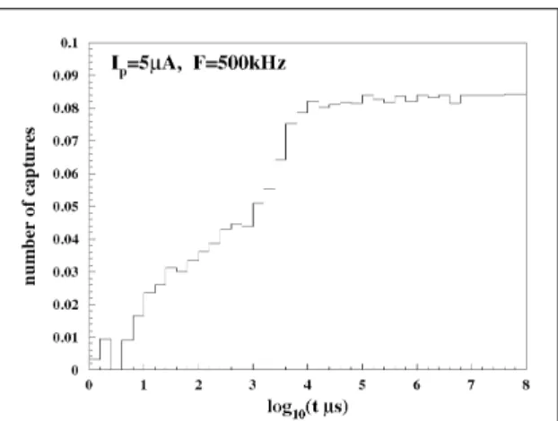
The number of Gd(n,γ) reactions in CARMEN as a function of time is given on Figure 14. An iterative procedure, taken into account the beam intensity and frequency, is used to estimate the number of neutron captures during 50 µs, the duration of the neutron multiplicity counting gate. The results is presented on Figure 15, two components are observed: the first one extending to 10 ms is a transition phase due to the beam setting-up; the second one is a steady state where the background becomes white. The value of the plateau gives the evaluated neutron background in 50 µs. The value of 0.09 is fully compatible with the neutron multiplicities which will be measured (between 1 and 4).
Figure 14 : Neutron capture time distribution in CARMEN normalised to 1 proton source.
23
Figure 15 : Number of neutron captures by gadolinium during a 50 µs gate as a function of time. t=0 corresponds to the first burst of beam, an average beam intensity of 5 µA
and a frequency of 500 kHz have been considered.
References
[14] C. J. Batty et al., NIM 68 (1969) p273-276
[15] B. C. Diven et al., Phys. Rev. 101 (3), 1012 (1956)
[16] M. Soleilhac, J. Fréhaut et J. Gauriau, Journal of Nuclear energy 23 (1969) 257 [17] G. Gupta et al., Nuclear Instruments And Methods 148 (1978) 77-84
[18] J. Fréhaut et al., Nuclear Data For Reactors, IAEA, Vienne, vol. II, p. 109 (1970) [19] J. Fréhaut et al., Nuclear Instruments And Methods 135 (1976) 511-518
[20] J. Jahnke et al., Lectures notes in physics, Springer, Berlin, p. 179 (1983). [21] U. Jahnke et al., Nucl. Instr. And Meth. A 508, 295(2003)
[22] M. Morjean et al.
[23] B.M. Quednau et al., Nucl. Phys. A606 (1996) 538-558 [24] X. Ledoux et al., Phys. Rev. C57 (1998)
[25] B. Lott et al., Nucl. Phys. A654 (1999) 803c-806c [26] A. Letourneau et al., NIMB 170 (2000) 299-322 [27] B. Lott et al., Nucl. Instr. And Meth. A 414, 117(1998) [28] Varignon et al., NIMB 248 (2006) 329-335
25
The GAINS set-up
Ph. Dessagne, M. Kerveno, G. Rudolf IPHC/DRS, CNRS6IN2P3-UdS, F67037 Strasbourg
A.J.M. Plompen
EC/JRC-IRMM, B-2440 Geel/Belgium C. Borcea, A. Negret IFIN-HH, 76900 Bucarest, Romania
Our set-up is dedicated to the study of the (n,xn γ) cross sections in view of the improvement of the (n,xn) reaction cross sections knowledge [30]. The prompt gamma-ray spectroscopy coupled to time of flight measurements are used to measured the (n,xn γ) reaction cross sections of interest.
The experiment will be performed with the GAINS set-up [31] which is currently used at the GELINA facility of EC-JRC-IRMM (Geel, Belgium) (see Figure 16 and Figure 17). It consists of 8 HPGe detectors placed at 110° and 150° with respect to the neutron beam direction (
Figure 17). For the neutron flux determination, we will use 238-U Fission chamber for which the efficiency will be precisely determine as it has been done for a 235-U fission chamber in our previous work[32].
26
Figure 17: Photo of the apparatus.
The acquisition system is composed of TNT2D digital cards [33]. We need a NIM signal from the pulsation of the accelerator and signals from beam monitors.
We bring high power supplies and racks. The electronic and DAQ is located close to the detectors and we need only internet connection to the PC’s located in the experimental area.
The Fission chamber is made of a sealed 238U sample (~ 20 mg) and P10 gas (90% argon and 10% methane) at 1 atm. (FC dimensions : ∅ = 150 mm, H = 66 mm) )
We need liquid nitrogen to cool the HPGe counters but we bring an autofill system.
References
[30] Measurement of (n,xnγ) reactions of interest for the new nuclear reactors, M. Kerveno et al., NEMEA-6: Exploring the frontiers of nuclear data and measurements, their uncertainties and covariances, Workshop Krakow, Poland 25-28 October, 2010 (online proceedings : http://www.oecd-nea.org/science/wpec/nemea6/)
[31] The gamma efficiency of the GAINS spectrometer, D. Deleanu, C. Borcea, Ph. Dessagne, M. Kerveno, A. Negret, A.J.M. Plompen, J.C. Thiry (2010) NIM A 624 (130-136)
[32] Measurement of (n,xnγ) reactions of at high precision, J.C. Thiry, et al., NEMEA-6: Exploring the frontiers of nuclear data and measurements, their uncertainties and covariances, Workshop Krakow, Poland 25-28 October, 2010 (online proceedings :
http://www.oecd-nea.org/science/wpec/nemea6/)
[33] TNT2 Digital Pulse Processor Functionalities & TUC control software, M.Richer, C. Santos, online http://www.iphc.cnrs.fr/-TNT-.html, IPHC, 2007
FALSTAFF
(Four Arm cLover for the Study of Fission Fragments)
D. Doré, Th. Materna, S. Panebianco, L. Mathieu DSM/Irfu/SPhN
F. Farget CNRS/IN2P3/Ganil
F.-R. Lecolley, J.-L. Lecouey, G. Lehaut, N. Marie CNRS/IN2P3/LPC Caen
M. Aïche, S. Czajkowski, B. Jurado CNSR/IN2P3/CENBG
L. Audouin, L. Tassan-Got CNRS/IN2P3/IPN Orsay
G. Bélier, A. Chatillon, B. Laurent, J. Taieb CEA, DAM, DIF F-91297 Arpajon
F.-J. Hambsch, S. Oberstedt IRMM, Geel, Belgium
A. Oberstedt, Orebro Universitet, Sweden
O. Litaize, O. Serot CEA/DEN/SPRC/LDM
The fission process discovered in 1938 by Otto Hahn and Liza Meitner is not completely understood, even after seventy years of intensive experimental and theoretical efforts. Experimentally, masses, charges and kinetic energies of fission fragments, energies and multiplicities of neutrons are the most studied observables. Even today, a full identification of fission fragments is a technical challenge, especially for neutron induced reactions (direct kinematics). For fission neutrons, the mean multiplicity has been measured in the past, but the
28
neutron multiplicity associated to each fission fragment is known for very few actinides and only in the thermal region.
The goal of the FALSTAFF experiment is to benefit of the high neutron fluxes in the MeV range that will be provided by the NFS facility and the possibility to use radioactive targets in this installation to perform experiments dedicated to fission fragment measurements of some actinides. Initial (before neutron evaporation) and final (after neutron evaporation) masses of fission fragments will be identified, thus providing the neutron multiplicity associated to each fission fragment. The nuclear charge of the light fragment will be also measured together with the kinetic energy of both fragments. This type of accurate nuclear data is needed both for fundamental studies and applications.
The detection of fission fragments in coincidence with FALSTAFF (Four Arm cLover for the Study of Actinide Fission Fragment) is based on energy and time-of-flight techniques. The combined measurements of velocity and energy provide information on the mass of the fragments before and after the neutron evaporation. Neutron multiplicity as a function of the fragment mass will then be determined. The charge will be identified using the ∆E-E technique.
A sketch of the experimental setup is presented in Figure 18. For velocity measurement, secondary electron detectors (SED with gaseous electron detector) and micro-channel plate detectors (MCP) are good candidates to reach the desired resolution (σ = 100 ps) with a good efficiency [34][35]. The dispersion induced by the thin emissive foils is not too large and the grids are almost transparent. MCP will be put close to and below the target as start detector. It will detect secondary electrons coming from the target. SED detectors can have large dimensions and then will be used as stop detectors and placed at about 50 cm from the target. A prototype of 20 cm x 15 cm has already been built and is being tested in Saclay and GANIL. The first tests give a resolution better than 150 ps. A position resolution of ~1.5 mm is expected.
Figure 18 : Falstaff experimental setup. Top view (left panel) of the full setup and side view (right panel) of half of the setup.
Fragment energies will be measured with segmented ionisation chambers (IC) placed behind the stop detectors. Anodes of the ionisation chambers will be segmented allowing charge identification by ∆E-E correlation up to Z~40. The charge identification provided by the ionisation chamber will allow correcting for energy losses in the different layers of the experimental setup.
29
GEANT4 simulations taking into account the geometry, resolutions (position, time, and energy) and uncertainties brought by the reconstruction method leads to a resolution of 2.6 amu (1.9 amu) for heavy (light) fragments. For this calculation, position, time and energy resolutions (σ) were assumed to be 1.5 mm, 150 ps and 1% respectively. A geometrical efficiency of ~1 % of 4π is reached with two arms (right panel of Figure 18). Based on an event-by-event analysis, the neutron multiplicity associated to each fragment mass has been determined. Result presented in Figure 19 shows that the foreseen resolutions will allow extracting the neutron multiplicity with a good accuracy. The large uncertainties around the mass 120 come from the low statistics. The gap between simulated and reconstructed multiplicities for 130<mass<150 can be corrected following the method developed by Terrell [36].
Figure 19 : Neutron multiplicity vs initial fragment mass. Theoretical (red symbols), simulated (black symbols) and reconstructed (green symbols) neutron multiplicities are
shown.
Simulations have shown the sensitivity of the mass determination on different parameters. In order to be more confident on the final design, we have defined three different phases for the setup development. The first one, consisting on a half-arm for the v-E measurement of one fragment, will be dedicated to the verification of the method and the simulations. The determination of the final masses of light fragments will be tested. The second one will allow checking the final masses determination of heavy fragments by the addition of a second ionization chamber for the energy measurement of the second fragment in coincidence. The experimental setup defined for this phase will be brought to NFS for D-One experiment. Finally, the last phase will lead to the initial and final mass determination of both light and heavy fragments with a good geometrical acceptance. A coherent experimental program, consisting on the measurement of a defined set of actinide targets, is foreseen to be performed at NFS with this final setup.
30 References
[34] A. Drouart et al., Nucl. Instr. and Meth. A579, 1090 (2007).
[35] J. Pancin et al., Proceedings of Journal of INST 12, 12012 (2009). [36] J. Terrell, Phys. Rev. 127 no3, 880 (1962).
31
Active targets based on liquid scintillator
J. Aupiais, G. Bélier, J.M. Laborie, B. Laurent, X. Ledoux, C. Varignon, S. Vayre CEA, DAM, DIF F-91297 Arpajon
1 Introduction
The use of active targets loaded with actinide open new opportunities of measurements for the study of n,xn reactions (see LoI 20) and for the study of fission reactions (see LoI 28). In particular coupling an active target with a 4π detector, like CARMEN, opens very attractive perspectives for experiments which could be performed at the NFS facility.
Direct measurement of (n,xn) reaction cross sections are difficult to perform on actinides since most of the time fission is the most probable exit channel leading also to neutron emission. The measurement of (n,xn) cross-section by detecting the x neutrons thanks to a 4π neutron detector requires to subtract the neutrons from fission inducing important uncertainties. An active target loaded with actinide gives a very efficient veto fission allowing the direct measurement of neutrons emitted in a non fission event.
The nuclear fission is a complex process not yet fully understood. One of the crucial question is the energy sharing at scission, that involves the whole physics of this complicated process. The understanding of this share requires to know nuclear deformations at scission, collective excitations, intrinsic excitation energy among other aspects. The measurement of several observable in coincidence is absolutely required to constrain or develop theoretical models. The observables that can be measured with a setup composed of an actinide loaded active target and the 4π CARMEN detector are the neutron multiplicities, the total energy released by gamma and the total kinetic energy of the fission fragments.
2 Description of the active target
The principle of this active target is to dissolve the actinide into an organic liquid scintillator. The advantages are the ease of fabrication, the high attainable actinide concentrations, the Pulse Shape Discrimination (PSD) capability of organic scintillators, the fast time response and the very low count losses. Moreover since the actinide is located in the active volume, this target has the potential capability of measuring the Total Kinetic Energy (TKE) of the fission fragments with no window effect, even for high sample masses. Since the scintillator response to fission fragments is not fully characterized this last feature will have to be proved.
The development of the target is inspired of the well known technique of Photon Electron Rejection Alpha Liquid Spectrometry (PERALS) which is commonly used for α spectrometry[38].
32
2.1 Response to fission fragments and light quenching
The experiments were performed by using Pyrex tubes inserted into a mechanical device containing a light reflector and a quantacon Burle 8850 photomultiplier associated to an ORTEC 265 base. The optical coupling was obtained with a silicone oil (Ordela Part no. LC-01). For the pulse shaping and shape discrimination a Mesytec MPD4 module was used. This module implements the zero crossing time technique for Pulse Shape discrimination (PSD) and delivers a Time to Amplitude Converter (TAC) signal. The shaped signal amplitude and the TAC were coded with a 7072 FAST Inc. ADC, associated to a FAST Inc. data acquisition system. The PH and TAC parameters were used to build a 2-dimensional histogram (PSD TAC%PH histogram).
Figure 20: (Color online) Left: (PSD TAC)%PH histogram for a natural uranium concentration of 10 µg/cm3. Three α-peaks can be distinguished which corresponds from lower to higher energies to the 238U, 234U and 252Cf decays. Right: same for a
concentration of 10 mg/cm3. The three α-peaks can not be resolved anymore due to resolution degradation associated to light quenching.
The left part of Figure 20 shows an example of histogram obtained with 1 cm3 scintillator into which 10 µg of natural uranium and 7 Bq of 252Cf were dissolved. Three classes of events are clearly seen. The long tailed one is associated to electrons. The 3 labeled peaks located at small amplitude and large TAC values are associated to the uranium and 252Cf α decays. Finally the bump at intermediate TAC values is associated to the 252Cf spontaneous fission. The right part of Figure 20 shows the same identification histogram obtained at a concentration of 10 mg/ml. A strong light attenuation is observed on the pulse height parameter while the pulse shape TAC is less affected for the highest concentration. Nevertheless for this last one, α-fission discrimination can still be obtained. The same study was performed with natural thorium and no light quenching was observed.
2.2 Detection efficiency
One of the major advantages of this new kind of target is its very high detection efficiency to heavy charged particles. In fact the count losses in such a system are only due to wall
33
effects and since the associated skin has very small thicknesses, of the order of the detected particle ranges, losses are very small. Those ranges are about 50 µm for 5 MeV alpha particles and between 20 and 30 µm for typical heavy and light fission fragments. In order to determine these losses dedicated simulations were performed with the MCNPX2.6 Monte-Carlo code, and the outputs were post-processed in order obtain the spectrum of the deposited energy by fission fragment pairs. Spectra for 3 different geometries of same volume are plotted on Figure 21, for the 252Cf spontaneous fission. They exhibit small tails whose associated relative losses are 3.1x10⁻⁶, 9.7x10⁻⁷ and 2.2x10⁻⁷ events/fission for an experimental threshold of 87 MeV. It can be concluded from these simulations that such kind of active target can be used as fission trigger with almost no losses. For α-decays these losses are less than 1 %, hence the target can be used to perform very precise measurement of actinide masses.
Figure 21 : (Color online) Simulated spectra of the deposited energy in the most probable spontaneous fission decay of 252Cf. The losses obtained from these three simulated spectra are respectively 3.1x10⁻⁶, 9.7x10⁻⁷ and 2.2x10⁻⁷ events/fission for the
PERALS (full line), the hemisphere (dashed line) and the sphere (dotted line) geometries. The y-axis has been zoomed in order to optimize the view of the tail. Hence
the full energy peak which contains 107 counts is truncated.
Consequently, this loaded active target can be used for (n,xn) experiments on actinides were a highly efficient fission veto is needed for precise direct measurement. Radiative capture measurements might be envisaged too.
2.3 Neutron monitoring
The main drawback of using an organic scintillator is the presence of hydrogen. But this disadvantage can be turned into benefit if a good discrimination between fission events and proton recoils can be obtained, providing the possibility to monitor the neutron flux with the active target. Experiments were performed on the CEA/DIF 4 MV accelerator with scintillators containing approximately 700 Bq of 252Cf. Neutrons were produced by the (d,T) reaction at energies around 18 MeV.
34
Figure 22 : (Color online) Bi-dimensional histogram obtained with the DIN scintillator loaded with 6 kBq of 252Cf. The neutron irradiation was performed at the
CEA/DIF 4 MV accelerator.
Figure 22 presents a 2-dimensional identification histogram similar to the one presented in Figure 20, but obtained with a numerical data acquisition system. The y-axis here reports the ratio of the slow/fast ratio obtained by the well known charge integration method. One clearly sees a separation between fission events and proton recoils (the long “banana”). The obtained figure of merit calculated over a restrictive energy domain (associated to the region of closest approach) is 2.5. It can be concluded from this study that the target can be used as a neutron flux monitor, leading to precise measurement since the measured flux is exactly the one inducing the measured induced reaction. This technique eliminates systematic uncertainties associated to target geometry, neutron transmission.
3 Conclusions
The presented active target is very promising for triggering purposes in (n,xn) and fission experiments thanks to the very high detection efficiencies, and especially for fission fragments. It can also be used for neutron flux monitoring, providing very precise measurements for experiments dedicated to cross sections measurements. In the context of fission studies, its capability to measure the Total Kinetic Energy will be studied. If the energy resolution is good enough (less than 10 %) the target can be used in experiments devoted to energy sharing in fission studies.
References
[37] G.Bélier & al. NIMA664(2012)341. [38] W.J. McDowell, NAS-NS-3116, 1986.
35
Conclusion
The Neutrons For Science facility is designed to host a broad panel of detectors to perform experiments aiming at various physics cases, like academic and applied physics, electronic, biology or industrial applications…
This report gives a short list of detection set-ups that are planned to be used at NFS. This list is not exhaustive and covers only a small part of the ups potentiality of NFS. The set-ups presented here are dedicated to the study of neutron induced fission, light charged particle production and (n,xn) reactions. Most of the presented detectors already exist and have been used at other facilities, some others are under development. In all cases, the experiment will come with its own electronics and data acquisition system. The home detection and acquisition system of NFS is limited in the neutron beam characterization, i.e. one time-of-flight signal recorded in a TDS, and two signals from the beam monitoring, with their energy sampling in an ADC.
37
Letters Of Intents for Day-One experiment at NFS
These Letters Of Intents have been submitted to the Scientific Advisory Committee. They are presented by physics cases, the name of the spokesperson is mentioned.
● Neutron induced reactions studies :
LoI_13 : Study of pre-equilibrium process in (n,xn) reaction, X. Ledoux
LoI_14 : Comparison between activation and prompt spectroscopy as means of (n,xn) cross section measurements, M. Kerveno
LoI_20 : Direct measurement of (n,xn) reaction cross sections on 239Pu, G. Bélier LoI_21 : Light-ion production studies with Medley, S. Pomp
● Fission :
LoI_15 : Fission fragment distributions and neutron multiplicities, D. Doré
LoI_22 : Fission fragment angular distribution and fission cross section measurements relative to elastic np scattering with Medley, S. Pomp
LoI_28 : Study of the fission process and fission cross-section measurements, G. Bélier
● Cross-section reaction measurements by activation technique: LoI_16 : Proton and deuteron induced activation reactions, P. Bem LoI_24 : Neutron-induced activations reactions, A. Klix
● Biology :
LoI_23 : Response of Mammalian cells to neutron exposure, C. Hellweg
● Detector development :
39
The NFS collaboration
X. Ledoux, E. Bauge, G. Belier, T. Caillaud, A. Chatillon, T. Granier, O. Landoas, J. Taïeb, B. Rossé, I. Thfoin, C. Varignon, CEA/DIF, Arpajon, France
V. Blideanu D. Doré, F. Gunsing, S.Panebianco, D. Ridikas, A.Takibayev,
CEA/DSM/IRFU/SPhN, Saclay, France
M. Aïche, G. Barreau, S. Czajkowski, B. Jurado, CENBG, Gradignan, France
G. Ban, F. R. Lecolley, J. F. Lecolley, J. L. Lecouey, N. Marie, J. C. Steckmeyer, LPC,
Caen, France
P. Dessagne, M. Kerveno, G. Rudolf, IPHC, Strasbourg, France
P. Bem, M. Majerle, J. Mrazek, J. Novak, E. Simeckova, NPI, Řež, Czech Republic
C. Gustavsson, S. Pomp, Department of physics and astronomy, Uppsala University, Sweden
U. Fischer, K. Klix, S. P. Simakov, KIT, Karlsruhe, Germany
B. Jacquot, F. Farget, J.P. Wieleczko, GANIL, Caen, France
L. Perrot, L. Tassan-Got, IPNO, Orsay, France
M. Avrigeanu, V. Avrigeanu, C. Borcea, F. Negoita, M. Petrascu, NIPNE, Bucharest,
Romania
S. Oberstedt, A.J.M. Plompen, JRC/IRMM, Geel, Belgium
M. Fallot, L. Giot, Subatech, Nantes, France
G. Smith, I. Tsekhanovich, Department of Physics and Astronomy, University of
Manchester, Manchester, UK
O. Serot, CEA/DEN, Cadarache, France
E. Balanzat, B. Ban-d’état, S.Bouffard, S. Guillous, J. M. Ramillon, CIMAP, Caen,
France
A. Oberstedt, Örebro University, Örebro, Sweden