HAL Id: in2p3-00664321
http://hal.in2p3.fr/in2p3-00664321
Submitted on 30 Jan 2012
HAL is a multi-disciplinary open access
archive for the deposit and dissemination of
sci-entific research documents, whether they are
pub-lished or not. The documents may come from
teaching and research institutions in France or
abroad, or from public or private research centers.
L’archive ouverte pluridisciplinaire HAL, est
destinée au dépôt et à la diffusion de documents
scientifiques de niveau recherche, publiés ou non,
émanant des établissements d’enseignement et de
recherche français ou étrangers, des laboratoires
publics ou privés.
GANIL D.C. power converters: improvements of the
response to mains fluctuations. Mains voltage harmonic
filtering
G. Duguay
To cite this version:
G. Duguay. GANIL D.C. power converters: improvements of the response to mains fluctuations.
Mains voltage harmonic filtering. EPAC 88 - First European Particle Accelerator Conference, Jun
1988, Rome, Italy. pp.1053-1055, 1988. �in2p3-00664321�
1053
G,ANIl. D.i‘. POWER CON'JERTFRS : IMPROVEMENTS OF TiiE RESPONSE TO MAINS FLIJ,'T[JATION.?.MAINS VOLTAGE HARMONIC F‘ILTERTNC G. DLIGAY and GANlI. POWEZR Supply Croup GANTL - B.P. 5027 - F 14021 CAEN CEDEX
SUMMARY
After a brief review of the methods used to simulate the mains steps, we describe the modifications brought to our DC Converters in order to protect them against the mains fluctuations. It was mostly necessary to avoid the disjunctions due to the excessively sensitive protective and relay systems and to improve the time-response of the electronic drive stages.
The second part deals with the description of a 20 KV two cells harmonic filter used to reduce voltage distorsions on the 20 KV CANIL network.
1. INTRODUCTION
Ganil is composed of three cyclotrons connected in cascade, an analysing spectrometer and a beam distribution system (9 experimental rooms).
The big SSC magnets, dipoles and Qpoles are powered by more than 420 D.C Converters bought from various e'uropean makers. ~nong these :
- 40 converters (from 30 KW to 1 MU) are current regulated by thyristor phase control.
All the others nre Series-transistol- controlled.
2. CONVERTERS RESPONSE TO MAINS STEPS
The experience gained during the first two years of beam operation showed that beam was often lost for many hours after disjunctions of some PC (power converters) or variations of magnetic field. The accelerator tuning had to be done again mostly due to a necessary recycling of the cyclotron magnets. All these disturbances were themselves caused by short mains fluctuations occuring during stormy weather
2.1 Simulation of mains uerturbations
3 kinds of simulations were used :
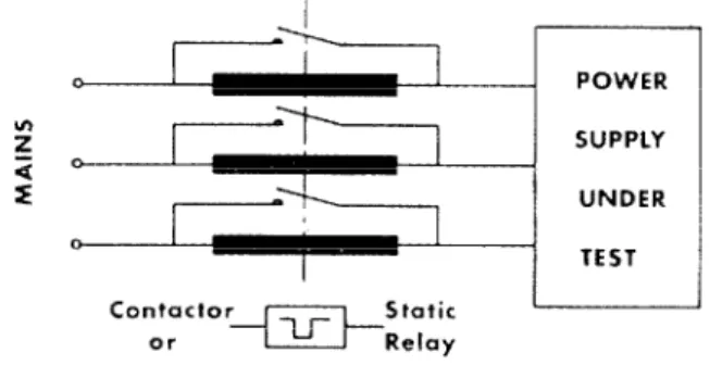
a. on the 380 V mains feeding the P.C to be tested we introduced series impedances (fig 1) either on the
380 V power circuit or
380 V auxiliary circuit or both.
b. The same method was used on the internal 20 KV network i.e. affecting the whole facility.
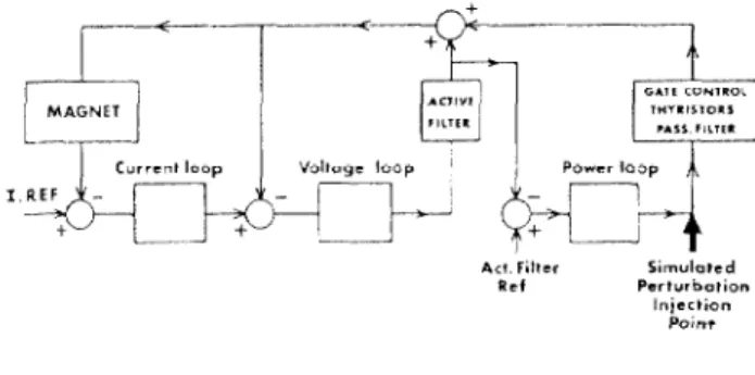
c. The third method was purely electronic. It consists in sending a voltage pulse to the input of thyristor gate control for thyristor converter or to the base of power transistors for series transistor regulated converter (fig 2 and 3). The absolute value of this pulse amplitude should be the same as the one that would be seen at the injection point if the perturbation were real. The pulse level is calculated taking into account the operating converter level and the Voutput to Vdrive transfer function.
With careful1 calibration, this method proved to be very convenient and accurate - in fact it was used most of the time
0
I-7
POWER 2 SUPPLY ;i o I: 1 UNDER 0 TESTFig 1 Simulation of mains deeps
2.2 Mains steps level
It has been found by observing the real mains steps on the 90 KV network feeding GANIL
that
in mostof the cases the voltage fluctuations had an amplitude of :
< 40 % when only one phase was involved
< 25 % when occuring on the 3 phases simultaneously
In 1984. we decided to systematically try to The average duration being in the order of .2 locate faults inside the power supplies ar.d to fix the to .4 second.
problem. Due to the random character of these mains We therefore conccwt rated on these pertur-hn- fluctuations we had to find a way to simulate them. tion levels,
It is to be mentioned that foreseen impro- vements were only possible due to the fact that the power transformers had a sufficient voltage margin.
Act. Fitlcr Simulo,cd Rc‘ Parturbo,ion
Injection Point
Fig 2 Block-diagram of a thyristor converter showing the perturbations
introducing point
As a consequence, when mains voltage was resuming to its rated value the electronics became fully saturated, control lost and over-current was detected, resulting in power disjunction.
On the whole, we had to increase the open loop Gain x Bandwidth product while not taking any risk of saturating any Op. Amp.
However, increasing the gain-bandwidth product was not always possible since it sometimes led to loop instabilities during start-up and at low level operation. So, we rather used a non linear way to increase amplification. See Fig 4. This new circuit gives a fast response to mains perturbations and it has no effect on "normal" control signal ; the Zener-resistor-diode network prevents any charge of Cl capacitor above what is necessary.
2.3 Origins of the Dower converters disturbances a. Disiunctions
Main power switches or contactors energized by 220 V were sanerally not able to withstand mains deeps of the orde; of 30 %. We chose to feed them with 220-V from an inside U.P.S. (Uninterruptible power supply) network. FVXtl Active Filter GATE CONTROL RECTIFIER FILTER
b. Converters protective systems
They were often disturbed by drops on +/- ?L v DC auxiliary voltages. On thyristor converters these voltages are given by a 220/18 V AC transformer alSO used for pulse synchronization, therefore it was impossible to use the GANIL U.P.S.
network to maintain the voltages. Lack of room and s+ required intensities (of more than 1 A) did not allow
the use of a capacitor bank. Finally the +/- 24 V auxiliaries were secured by two floating charged Ni-Cd batteries.
c. Sensitivities of the protections
In addition, some protections like saturation detection phase failure detector, ripple, earth fault had to be delayed and tuned again.
d. Improvement of control electronics
On thyristor converters we should note that the active filter was not able to deal with mains
pprturhat ions larger than 1 % and, of course,
corrections had to be done on the power loop.
But we found this power loop having poor
Fig 4 Thyristor converter powerloop a. before modification
b. after modification
Gl N 3GO Cl N 0.5 CO vo - 2 to 3 v
performances caused by : Remarks :
- too low an open loop gain inside the - On GANIL thyristor converters mains steps do not 10 Hz - 100 Hz frequency band, lead to pulses desynchronization.
some Op Amps working near saturation - on transistor regulated converters the same kind of (12 -13 V for Vcc - 15 V), adjustements were also needed - specially limitations
integrators or P.I. amplifiers having of voltage swings and augmentations of open loop gain large voltage swings and therefore storing too much and bandwidth.
er~rgy during mains steps.
l-
‘;iq
.----.
:;
-w
cuircnr
loop “ol,oge
loop
I. RlF
,._.-
+d --
II-
-
1 <+-.._..,T
f
Sii7l"ld~d Pcrtvrbafion lni;;;;Tn 2.4 ResultsWith all these improvements : - unwanted converters disjunctions desappeared,
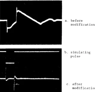
- we strongly reduced the DC voltage variations of the GANIL power converters. For example on SSCl main magnet and with a 3 phase - 20 % 500 ms perturbation we obtained the results illustrated on Fig 5.
On the other hand for this same step SSCl magnetic field variation which used to be 7 Gauss is now around .3 Gauss (B - 16000 G). On GANIL as a whole, a loss of beam and retuning of the machine after a mains perturbation is now reduced to approximately half an hour.
Fig 3 Block-diagram of a series-transistor converter
1055
Fig 5 P.C. output voltage
simulated perturbation a. before modification b. simula: i:lg plsr c. after modific.it.ion 2.4 MVAR 90KV/2OKV \ 3MVAR 16 Transformers
Fig 6 Network and A.C. filter
configuration with
Results :
AS can be seen on Fig 7 the two third order filters give appreciable results in reducing harmonic distorsion.
However a slight increase of H3 is observed and until now we have some reliability problems with 20 KV capacitors.
3. HARMONIC FILTERING
In addition to mains fluctuation problems GANIL P.C suffered from heavy mains harmor.ic distorsions (generated by the converters themselves)
Among others disturbances we can notice : - phase noise in voltage or power loops o-t the thyristor converters,
disjunctions produced by detection of
sar.uration or excessive ripple on the active filter
(thyristor P.c),
excessive beating of po-.wr trar.sforewr
and ii ltering cells (series transistor P.C).
F~lrthermo~-r, GANI I, powrr consumption during npt*ratior. ranges from 5 to 8 MU while reactive power fluctuates from 6 to 9 MVA (‘according to the energy requier-rd)
It WRS drcided to lower the reactive power cor~surnp t i on with a compensator which would also achieve bar-manic filtering.
Tl1< rwtwork and filter configuration is shown on Fig 6. It should be mentionned that the 90 KV short-circl;it capacity is about 400 MVA (+/- 50 MVA).
01115' harmonics 11 and 13 (and with less sharpness H23 and H95) were in fact disturbing the GkUIL power ~onvcrt<‘rs.
Harmonics 3 and 5 are not generated by GANII., thev arc pre-existing, on 90 KV external distributor netwo:-k Howc~vr r- t 0 avoid antiresonance with this rwtwork reactance a H5 filter has to be installed and !-he 7 i 1 t e :- HI I ,/ 1 3 should not work without the H5 in service.
‘I’hc~reforr ix0 third order, low
Q
factor:-t”;<>i:;iI,t filters are used in parallel ['I.
The first OIlI? :uned on 175 Hz (H.5.5j !‘c,,it ill-t's
0 fact = 2 Reactive power - 3 MVAR t: losses - 5 KW
- The sctcond onv tuned on 575 Hz (Hll. 5)
‘.,
‘fact - <+ Keactjw powrt- - 2.h MVAI!
c 1O~SC~S - 1.5 KU
m “3’. / Vcltage
~ d sfnrs~or
order
Fig 7 Filter attenuation
Acknowledgement
We gratefully thank E.D.F. (Electricit& de France) particularly Mrs BERNARD from C.1.M.E NORMANDIE - PARIS and Mr PLANCHE]'] from D.E.R.for the help and advices they gave us for the improvements of our power converters.
REFERENCES
I] Desensibilisation des alimentations aux perturbations secteurs. GANIL internal Report R/17.86/1111.
:2] R. PLANCHE : Insensibilisation du GANIL vis-a-vis des crew de tension - resume des actions - Bilan et conclusion.
E.D.F. Rapport HM562614RP/HS June 86. !3] Maitrise des harmoniques dans les reseaux
industriels JP CAMATTE -G LE CAM CGEE-ALSTHOM CZRED Congress April 1483 Liege (Belgium).