HAL Id: insu-00355496
https://hal-insu.archives-ouvertes.fr/insu-00355496
Submitted on 22 Jan 2009HAL is a multi-disciplinary open access archive for the deposit and dissemination of sci-entific research documents, whether they are pub-lished or not. The documents may come from teaching and research institutions in France or abroad, or from public or private research centers.
L’archive ouverte pluridisciplinaire HAL, est destinée au dépôt et à la diffusion de documents scientifiques de niveau recherche, publiés ou non, émanant des établissements d’enseignement et de recherche français ou étrangers, des laboratoires publics ou privés.
Numerical analysis of squeal instability
Francesco Massi, Laurent Baillet
To cite this version:
Francesco Massi, Laurent Baillet. Numerical analysis of squeal instability. International Congress of Novem; 2005, 2005, St Raphael, France. pp. 10. �insu-00355496�
Numerical analysis of squeal instability
F. Massi and L. Baillet
University of Rome “La Sapienza”, Department of mechanics and aeronautics
Via Eudossiana 18, 00186 ROME, ITALY
Contacts and Solid Mechanics Laboratory, INSA of Lyon,
bât. Jean d’Alembert, avenue Albert-Einstein, 69621 VILLEURBANNE Cedex,
FRANCE
Abstract
The name “brake squeal” groups a large set of high frequency sound emissions from brake systems, generated during the braking phase and characterized by a periodic or harmonic spectrum. This paper presents two different numerical approaches to identify the mechanism bringing to the dynamic instability, producing squeal noise. The first approach performs a finite element modal analysis on the brake system, to identify the eigenfrequencies of the components and to relate them to the squeal frequencies. The second one uses a specific finite element program, Plast3, appropriate for non-lineardynamic analysis in the time domain and particularly addressed to contact problems with friction between deformable bodies. The use of this program allows to verify the behavior of the components and to link results obtained from the time analysis and the modal one. The study presented is carried on a simple model, composed by a disc, a small pad and a beam supporting the pad, to simplify the behavior of its components.
1
Introduction
Brake noise is an example of noise caused by vibration induced by friction forces. Disc brake squeal can occur in the frequency range between 1 kHz to 20kHz, and over. Squeal is a difficult subject partly because of its strong dependence on many parameters and partly because the mechanical interactions in the brake system are very complicated, including non-linear contact problems at the friction interface. Kinkaid et al [1], in their extensive review paper on brake squeal phenomenon, concluded that “despite a century of developing disc brake systems, disc brake squeal remains a largely unresolved problem”.
Many researchers, North [2], Akay et al.[3], Flint and Hultén [4], in their studies on the dynamic behavior of brake systems stressed the coincidence between squeal frequency and mode frequencies of the system. Particularly, they associated the squeal phenomena to the coalescence of two eigefrequencies of the system. Their studies suggested a complex modal analysis of brake system models as a tool of investigation on squeal.
The main lack of these researches is the use of a linear model of the system, despite the strong non-linearity of the associated contact problems. Moreover linear models have been used to predict the rising of squeal phenomena [5], but they are useless to understand the behavior of the system in time and the relationship between its features and the non-linear aspects of the problem.
Therefore, this paper is aimed to develop and compare two different models: a linear FEM, used to predict squeal frequencies through a complex eigenvalues analysis, and a non-linear FEM developed for contact problems [6], useful to investigate the characteristics of squeal phenomena in time domain.
2
Numerical models
The model presented in this paper (figure 1) represents a simplified brake system. An experimental set-up, schematized by this model, is under construction. The geometry of the model is influenced by the geometry of the experimental set-up. The brake disc consists of an annular volume with external radius equal to 120mm, internal radius 50mm and thickness 10mm. Its Young modulus is equal to 210000 MPa and its density 7800 kg/m3. The brake pad consists of a cube 10x10mm with material density equal to 2500 kg/m3 and Young modulus variable from 6500 to 80000 MPa. The pad support is modelled by a beam 10x10x100mm. Four rows of springs, twoon each side, hold the beam in the horizontal (friction force) direction, and model four thin aluminum plates that will hold the pad support in the experimental set-up. The value of the springs stiffness (8.422exp6 N/m each spring, 11 springs each row) was determined with the aim the same normal stiffness of the thin plates. The other side of the springs is fixed. Density and Young modulus of the beam, respectively 2100000 MPa and 78000 kg/m3, are larger than those of steel, because the beam must model a big block that will be used in the experimental set-up.
The contact force is modelled by two different contact elements.
Figure 1: Model of the system
2.1
Linear model
Ansys®, a commercial FEM software, was used to investigate the dynamic of the system and to calculate its complex eigenvalues in function of different parameters. The element of Ansys, SOLID45, is used to mesh all the solid components of the system. SOLID45 is a 3D brick element characterized by 8 nodes, with 3 translational degrees of freedom per node; the shape functions are linear.
The 3-D geometry of the subsystems is discretized with a mapped mesh. Compared with the free-mesh which uses tetragonal elements, the mapped free-mesh allows for a reduction of elements and computation resources. Moreover the mapped mesh permits to generate a grid of the disc which is axial-symmetric. (A non-axial symmetric mesh causes the double modes of the disc to split also in free conditions). Two different meshes of the disc have been studied. The former (figure 2-a) is the same mesh used on the non-linear FEM model; it is completely axial symmetric, but it has a large
number of elements (10240 disc elements). The second (figure 2-b) is not completely axial symmetric, but it has a lower number of elements (2412 disc elements) and a thinner mesh in the contact zone.
Figure 2: a) Disc mesh with 10240 elements; b) Disc mesh with 2412 elements
A comparison between the dynamics of the two models with different meshes has been performed. The error percentage in the frequency range of interest (1-20 kHz) is lower than 5% and lower than 2% until 10 kHz (figure 3). Therefore, because of the reduction of computational resources and because of the thinner mesh in the contact area (where the contact elements have to be placed), the second mesh has been preferred for the linear analysis.
Figure 3: Error percentage between the eigenfrequencies obtained with the two meshes
The contact elements are implemented in the FEM using the MATRIX27 element which allows for the definition of an element stiffness matrix characterized by 2 nodes and that can be non-symmetric.
For each couple of nodes of the pad and the disc in the contact area, the following force components are introduced in the element MATRIX27 stiffness matrix:
(
(
)
)
p d n d y p d n d z z z k F z z k F − ⋅ ⋅ µ − = − ⋅ =(
(
)
)
p d n p y p d n p z z z k F z z k F − ⋅ ⋅ µ = − ⋅ − = (1)where, d = disc, p = pad, kn is the contact normal stiffness between the two nodes, z the displacement in the normal direction to the contact surface, Fzand Fy are the contact forces in the
normal and friction direction, respectively, µ is the friction coefficient. In the contact area, the disc and pad surfaces are meshed with 10x10 elements, 121 nodes for each surface. That is, 121 contact elements over the contact area between the nodes of the disc surface and the nodes of the pad surface are introduced. The main difficulty on the definition of the linear model is that the nonlinear behavior of the contact must be modelled by linear elements.
The Coulomb’s law with a constant µ describes the friction interaction between disc and pad. The contact stiffness Kn introduced in the linear model has been approximated in the non-linear FEM model by loading the pad support with a force ramp. Plotting the load in function of the distance between the second row of nodes of the disc and the second row of nodes of the pad in the contact area, and interpolating this curve with a linear function, a contact stiffness equal to 2.5895exp8 N/m is determined, for a modulus of Young of the pad equal to 16000 MPa.
2.2
Non-linear model
The explicit dynamic three-dimensional finite element code Plast3 [6] is used to simulate the behavior of the system. This software uses a forward incremental Lagrange multiplier method [7], which enables the evaluation of the normal and tangential contact stresses in the contact region as well as the determination of whether the contact surfaces stick, slide or separate locally. The forward increment Lagrange multiplier method equations set is constructed using the equations of motion developed via the principle of virtual work at time step tn
(
tn =n⋅∆t)
augmented by the displacement constraints acting on contacting surfaces at time tn+1(
tn+1=tn+∆t)
:
{
X u u}
0 G F G F u C u M n 1 n n 1 n n n n 1 n n n n t t t t ext t t t t int t . t t .. ≤ − + ⋅ = λ ⋅ + + ⋅ + ⋅ + + + (2) n tλ is the contact force vector acting on the nodes at the contact surface, 1 n
t
G + the global assembled matrix of the constraint elementary matrices,
(
)
n 1 n n 1 n t t t t X u u
X + = + + − is the coordinate vector at time
1 n
t + , M and C are the mass and the damping matrices, respectively, int
F and ext
F are the nodal vectors of internal and external forces, u& and u&& the velocity and the acceleration vectors. The used friction law is the standard Coulomb friction model without regularization of the tangential stress against the tangential velocity component.
The three deformable bodies are meshed with cubic elements of eight nodes. The model of the support is composed of 400 elements. The pad is composed of 1000 elements. The disc is composed of 10240 elements. Both surfaces are considered flat as the initial roughness is erased in the first moment of contact between the two bodies.
At the initial time an increasing force, F, is applied in the z-direction until it reaches a pre-selected threshold value which corresponds to a uniformly distributed normal displacement on the top of the pad support. The application of this force puts the pad in friction contact with the disk whose linear speed is kept constant throughout the simulation time. Like for the Ansys model, four rows of springs hold the beam in the horizontal (friction force) direction. The other side of the springs is constrained depending on x, y and z. The nodes belonging to the inner disc radius are constrained depending on the z-axis and have an imposed rotational speed ω. The material properties and bodies dimensions are the same reported for the linear model.
3
Frequency comparison
The main purpose of this paper is to compare the two models in order to use the linear one for predicting squeal condition, and the non-linear one for investigating squeal characteristics, in the same conditions, by studying its time behavior. Therefore a frequency analysis has been conducted with Plast3 to compare the eigenfrequencies and the deformed shapes of interest for the non-linear and the linear model obtained with Ansys.
At the initial time the same increasing force F, used in the runs for braking simulation, is applied on the pad support in the z-direction until it reaches the pre-selected threshold value. This is done to have the same preloading conditions during braking simulations. Then, an impulse is applied at a node of the disc in the z-direction and the response of the system is calculated on nodes belonging to four different circumferences on the upper surface of the disc. The results are then elaborated with Matlab to obtain the Frequency Response Function on each node and to reconstruct the deformed shape at each eigenfrequency. The material properties are the same listed above, with the modulus of Young of the pad equal to 25100 MPa. With the same parameters a modal analysis has been conducted with Ansys.
Here we focus the attention to the normal modes of the disc, which are involved in the squeal mechanism. The disc modes are characterized by nodal diameters and nodal circumferences: the (n,m) mode of the disc is characterized by n nodal circumferences and m nodal diameters. The disc is characterized by an axial symmetry: therefore the modes of the disc are generally double modes. We use the following notation to name coupled system modes:
- mode (n,m) a nodal diameter is coincident with the contact point;
- mode (n,m+) an antinode is coincident with the contact point.
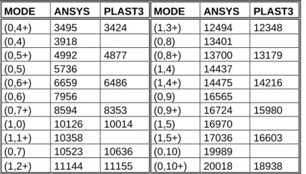
Table 1 lists the frequencies calculated for the linear model and for the non-linear one.
MODE ANSYS PLAST3 MODE ANSYS PLAST3
(0,4+) 3495 3424 (1,3+) 12494 12348 (0,4) 3918 (0,8) 13401 (0,5+) 4992 4877 (0,8+) 13700 13179 (0,5) 5736 (1,4) 14437 (0,6+) 6659 6486 (1,4+) 14475 14216 (0,6) 7956 (0,9) 16565 (0,7+) 8594 8353 (0,9+) 16724 15980 (1,0) 10126 10014 (1,5) 16970 (1,1+) 10358 (1,5+) 17036 16603 (0,7) 10523 10636 (0,10) 19989 (1,2+) 11144 11155 (0,10+) 20018 18938
Table 1: Modes and frequencies (Hz) calculated with Ansys and Plast3 (postprocessing in Matlab)
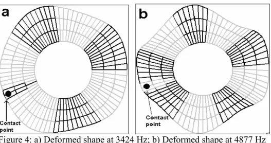
The eigenfrequencies calculated with Plast3 miss the modes with a nodal diameter in the contact point because the impulse was given at a node of the contact area and only modes with an antinode at this point are exited. The excitation point has been chosen in order to excite modes that can be involved in the squeal phenomena. In fact in [5] it is shown that, using pads with reduced dimensions, only modes with an antinode in the contact point are involved in squeal phenomena. Figure 4-a and 4-b show the deformed shapes related to the modes (0,4+) and (0,5+) calculated with Matlab from the data obtained with Plast3. The same modal shapes obtained with Ansys are shown in figure 6-a and 6-b.
Figure 4: a) Deformed shape at 3424 Hz; b) Deformed shape at 4877 Hz obtained with Plast3 (postprocessing in Matlab)
4
Complex modal analysis
A complex eigenvalues analysis provides the tool to trace the instability regions of the system. The numerical eigenvalues extraction is performed with the Damped Method by Ansys and repeated in function of the Young modulus of thepad material, from 6500 to 80000 MPa. The analysis is first performed in the frequency range from 900Hz to 30000Hz. Then, the analysis is focused on the instability region because all the system modes are included in this analysis and, due to the adopted algorithm, the solution is accurate only in a small frequency range.
Figure 5 shows the complex eigenvalues analysis performed with Ansys between 2500 and 6000 Hz. Two different instabilities are predicted at 5000 Hz and at 3500 Hz. The former starts for a modulus of Young equal to 20000 MPa while the second starts at 24000 MPa. Both of them exist until the maximum value of the range of interest.
Figure 5: Eigenfrequencies of the System in function of the Young Modulus of the pad,
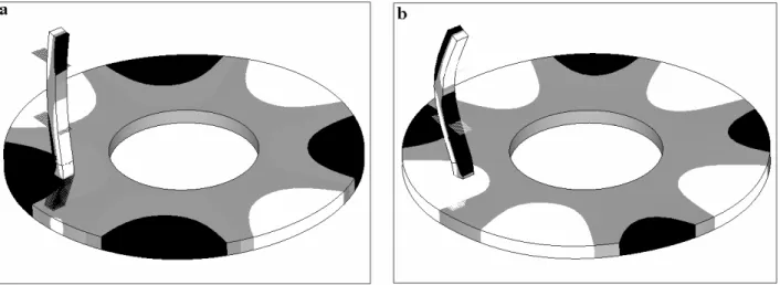
The solution is affected by instabilities that depend on small parameter variations. The occurrence of these inaccurate solutions increases when the frequency range increases, and, within a frequency range, for higher order modes. Nevertheless the complex eigenvalues analysis is robust enough to distinguish between such numerical instabilities and the mode-lock-in instabilities which occur only when two eigenfrequencies of the system coalesce. Figures 6-a and 6-b show the deformed shape of the unstable modes. The instability at 3500 Hz is characterized by the vibration of the disc at its (0,4+) modal shape. The instability at 5000 Hz presents the (0,5+) modal shape of the disc. The antinodal at the contact point with the pad is lower than the others because of the presence of the pad and its support.
Figure 6: a) Unstable mode at 3500 Hz; b) Unstable mode at 5000 Hz, obtained with Ansys
5
Time contact analysis
Once the instability regions of the system are identified with the modal approach, the values of the parameters bringing to squeal condition can be introduced in the non-linear model, in order to study the features of the squeal phenomena in time domain. Aim of the present paper is to demonstrate the agreement of the two models and the possibility of using the linear model approach to identify the proper parameters to introduce into the non-linear model.
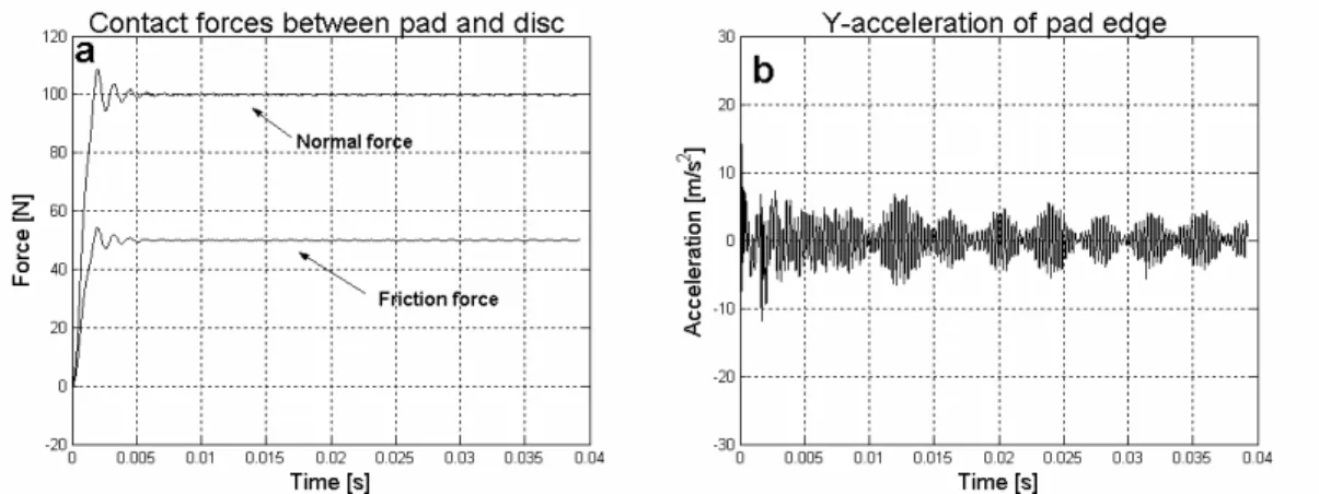
Therefore different values of the pad modulus of Young have been introduced in the non-linear model. Figure 7-a shows the sum of the normal and tangential contact forces behavior in time for a modulus of Young of the pad equal to 16000 MPa and coefficient of friction equal to 0.5. Figure 7-b shows the acceleration in the y-direction (relative velocity direction) of a nodeplaced at the edge of the pad. The acceleration oscillations decrease in time after the first contact between the pad and the disc. There are no remarkable oscillations in the sum of the contact forces. We conclude that within these values of the parameters, like predicted with the modal analysis, the system is stable.
Figure 7:a) Sum of contact forces; b) Acceleration of pad edge in the friction direction for pad Young modulus equal to16000 MPa – Plast3 simulation
Figure 8-a and figure 8-b show the same results described above for a Young modulus of the pad material equal to 25100 MPa and coefficient of friction equal to 0.5. With these values of the parameters an unstable state characterised by a periodic steady state, with strong vibration of the system, is determined. The contact forces reach the threshold value and, after some instant, a strong oscillation with exponential growth starts and develops until a maximum value. Both the contact forces and acceleration oscillations have a sinusoidal behavior. Figure 9-a shows the Power Spectral Density of the acceleration. The vibration is characterized by one main frequency and its harmonics, as usual for squeal phenomena. The squeal frequency, 3430 Hz, corresponds to the eigenfrequency of the mode already found to be unstable with the modal analysis. In fact the investigation of the system vibration shows that the system is vibrating with the (0,4+) deformed shape of the disc. Figure 9-b shows the velocity in the z-direction of the system during the unstable condition. Like for the unstable mode calculated with Ansys (figure 6-a), also the vibration shape calculated with Plast3 has a lower antinode in the contact point.
Figure 8:a) Sum of contact forces; b) Acceleration of pad edge in the friction direction for pad Young modulus equal to 25100 MPa
Figure 9: a) PSD of pad acceleration; b) Velocity distribution in the z-direction for pad Young modulus equal to 25100 MPa – Plast3 simulation
The same unstable condition was found for a Young modulus equal to 39800 MPa. For this value the oscillation of the contact forces grows until the pad starts to detach completely from the disc surface, and the contact forces become equal to zero (figure 10).
Figure 10:a) Sum of contact forces; b) Acceleration of pad edge in the friction direction for pad Young modulus equal to 39800 MPa – Plast3 simulation
Figur 11: a) PSD of pad acceleration; b) Velocity distribution in the z-direction for pad Young modulus equal to 39800 MPa – Plast3 simulation
The results obtained with Plast3 on the non-linear model agree with the results obtained with Ansys on the linear model: we have instability for modulus of Young equal to 25100 and 39800 MPa, but
not for modulus of Young equal to 16000. These results correspond with the instability regions obtained with the modal approach.
6
Conclusions
Two different approaches for squeal investigation have been compared. The modal approach has been proposed from several authors to predict instability conditions of a system. A non-linear model, using forward incremental Lagrange multiplier method for contact simulation, is here proposed to study time behavior and non-linear features of squeal phenomenon.
Modal analysis is used for finding parameters to introduce in the model in order to have squeal. The same conditions have been obtained with the time analysis through the non-linear model. This validates the match between the two models. Contemporarily the verified instabilities guarantee the validity of a linear approach for studying the arising of squeal phenomena.
It should also be observed that the modal analysis presented in this paper suggested two different possible squeal frequencies for the same values of the parameters. In the non-linear contact analysis just one of these instabilities has been found. In effect the modal analysis is appropriate to individuate possible squeal conditions and frequencies, by finding the eigenvalues of the system with positive real part (negative damping); nevertheless there is not yet an agreement on the “squeal index” [8] that should give the propensity of arising of the instability.
References
[1] N.M.Kinkaid,O.M.O‘Reilly, P.Papadopoulos, Journal of Sound and Vibration, 'Automotive disc brake squeal', 267, 105-166, (2003)
[2] M.R. North, 'Disc brake squeal, a theoretical model', Technical Report 1972/5, Motor Industry Research Association, Warwickshire, England, (1972)
[3] Akay, J. Wickert, Z. Xu, 'Investigation of Mode Lock-In and friction interface', Final Report, Department of mechanical engeneering, Carnegie Mellon University (2000)
[4] J.Flint, J.Hultén, Journal of Sound and Vibration, 'Lining-deformation-induced modal coupling as squeal generator in a distributed parameter disc brake model',254,1-21,(2002)
[5] O.Giannini,F.Massi, 'An experimental study on the brake squeal noise', Proc.International Conference on Noise and Vibration Engineering-ISMA, Leuven, Belgium (2004)
[6] L.Baillet, T.Sassi, Comptes Rendus de l’Académie des Sciences Paris, 'Finite element method with Lagrange multipliers for contact problems with friction', Series I,334, pp. 917-922, (2002)
[7] N.J. Carpenter, R.L. Taylor, M.G. Katona, International Journal for Numerical Methods in Engineering, 'Lagrange constraints for transient finite element surface contact', 32, pp. 130-128, (1991)
[8] Giannini O., 'Experiments and modeling of squeal noise on a laboratory disc brake', PhD thesis, University of Rome “La sapienza” 2004.