HAL Id: hal-00957471
https://hal.archives-ouvertes.fr/hal-00957471
Submitted on 2 Dec 2020
HAL is a multi-disciplinary open access
archive for the deposit and dissemination of
sci-entific research documents, whether they are
pub-lished or not. The documents may come from
teaching and research institutions in France or
abroad, or from public or private research centers.
L’archive ouverte pluridisciplinaire HAL, est
destinée au dépôt et à la diffusion de documents
scientifiques de niveau recherche, publiés ou non,
émanant des établissements d’enseignement et de
recherche français ou étrangers, des laboratoires
publics ou privés.
Forward Model Computation of Quasi-static Magnetic
Fields inside Electric Vehicles
Olivier Pinaud, Olivier Chadebec, Laure-Line Rouve, Jean-Michel Guichon,
Andrea Vassilev
To cite this version:
Olivier Pinaud, Olivier Chadebec, Laure-Line Rouve, Jean-Michel Guichon, Andrea Vassilev.
Forward Model Computation of Quasi-static Magnetic Fields inside Electric Vehicles.
IEEE
Transactions on Magnetics, Institute of Electrical and Electronics Engineers, 2014, 50 (2),
�10.1109/TMAG.2013.2283913�. �hal-00957471�
EHICLE electrification is widely promoted to answer environmental issues and reduce the reliance on fossil fuels. However, electric vehicles require a significant number of electrical devices within a quite small space (electric motor, power electronics, power battery, power cables, and so forth). Therefore, it may appear inside the cabin, electromagnetic fields due to these components. International Commission on Non-Ionizing Radiation Protection (ICNIRP) gives guide-lines to limit exposure to static [1] and time-varying [2] magnetic fields. Some studies [3], [4] have provided mea-surement results inside electric vehicles. Nevertheless, few works are dedicated to the identification and evaluation of this electromagnetic field by simulation. This goal is a great challenge because electric vehicle is a complex system to model. Providing tools and methods enabling electromagnetic fields computation will be useful for health protection assess-ment. Moreover, this tool could be applied to electromagnetic compatibility analysis for industrials manufacturers who need to predict possible issues during design process.
II. PRELIMINARY STUDY
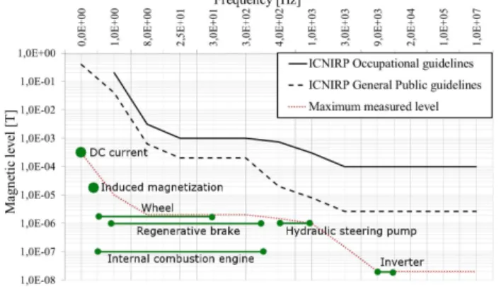
Several electric cars have been studied to evaluate the con-tribution (magnetic levels and frequencies) of each on-board electrical device. This paper leads to an exposure calculation according to ICNIRP recommendations [2]. Results show that even if each electric device produces a magnetic field far below the ICNIRP level (see Fig. 1), when considering all the contribution together during a drive test, the exposure criterion (that must remain under 100%), can reach ∼20% at startup.
For every car, the strongest field values are reached near the battery pack or power cables. Depending on their location inside the vehicle, the magnetic field inside the passenger cabin may increase. For example, in recent cars, the battery is often located under the passenger cabin. Even if battery pack is shifted at the rear (in the boot) or in the front (under the bonnet), power cables could locally increase the exposure.
Therefore, our measurements illustrates that for exposure purpose the whole contribution of the on-board equipment
Fig. 1. Magnetic field level and bandwidth encountered compared with ICNIRP recommendation.
must be computed. Our study also shows that the devices in which strong currents (or Ampere turns) flow are likely to generate the highest amplitude to electromagnetic fields.
For the studied cars, high currents are distributed inside batteries and along cables and correspond to extremely low frequencies (lower than a few hertz). For this bandwidth, recommendation levels are far higher than the measured ones. Nevertheless, this level goes down to 27µT in the 3–30 kHz bandwidth. This frequency range corresponds to new power wireless systems designed to reduce the size of the battery pack and supply energy to the vehicle when driving (see on line electric vehicle in Korea [8]). Inside these structures, lots of Ampere turns are developed, which may generate strong magnetic fields inside the car cabin.
For all these reasons, fields created by high currents must be carefully investigated. In this paper, the first sources we focus on are batteries and cables in a static approach because of the associated frequencies. We will show that their contri-bution inside the vehicle is strongly correlated to the current arrangement inside the battery, outside the battery, and to the shielding effect of the magnetic parts (chassis and frame). We provide a numerical tool and measurement methodology to assess the source level inside the car. Finally, the numerical model is applied to predict and study the reduction of this kind of contribution inside the cabin.
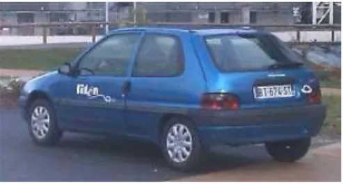
III. VEHICLEANALYSIS ANDASSUMPTIONS A three-door-utility electric vehicle from the late ’90s like in Fig. 2 has been chosen for this paper. This car is mainly made of ferromagnetic materials whereas recent vehicles may
Forward Model Computation of Magnetostatic Fields
Inside Electric Vehicles
Olivier Pinaud
1, Olivier Chadebec
1, Laure Line Rouve
1, Jean Michel Guichon
1, and Andrea Vassilev
21Electrical Engineering Laboratory of Grenoble, University of Grenoble, Grenoble 38400, France 2CEA-Leti, Grenoble Cedex 9 38054, France
Magnetostatic field inside a simplified electric vehicle-like geometry is analyzed. The developed model allows evaluation of the shielding effect of the magnetic chassis and frame. It also proposes an equivalent model for the power battery and cables. The study of different configurations leads to the field reduction inside the car.
Index Terms— Electric vehicle, magnetic field measurement, magnetic field simulation, magnetic shielding, magnetostatics.
I. INTRODUCTION
V
Fig. 2. Studied three-door-utility electric vehicle.
integrate more aluminum, plastic or carbon fiber parts for lightening purpose.
The vehicle ferromagnetic parts acquire a magnetization when subjected to local magnetic fields. This magnetization may produce a shielding effect inside the car with respect to these magnetic fields sources. Shielding effect must be characterized because most electric devices on-board vehicle are located outside the cabin and thus, their magnetic fields are attenuated by the car ferromagnetic body. As noticed, recent cars should integrate less ferromagnetic parts like plastic and thus the shielding effect could be reduced.
As explained in Section II, we will mainly focus on modeling sources like batteries and cables, which are static or extremely low-frequency weak field sources. In a first step, the shielding effect is characterized inside the earth magnetic field (weak field of ∼40 A/m in France) because this characteriza-tion is easier in a uniform field. Then, fields created by high currents (few hundreds of amperes) flowing inside the power batteries and associated power cables will be investigated. In both cases, the proposed modeling is magneto static.
IV. NUMERICALMODELING
In our approach, the geometry of the ferromagnetic parts of the vehicle and the associated surface meshing are created in Flux3-D [5] software. The problem is solved with an integral formulation developed in our own software Locapi [6], better adapted than finite-element method to compute accurately the magnetic field in air region. As the method is associated to a fully dense matrix system, an adaptive multilevel fast multipole method is used to limit memory requirement and to increase the computation speed. The magnetic moment method is precisely presented in [7].
In the following parts, a field applied along the longest dimension of the car is called longitudinal, transverse if along the width and vertical if along the height.
A. Induced Magnetization due to Earth Magnetic Field Earth magnetic field varies on the globe surface but can be assumed homogeneous and constant on the zone where a car is moving. Depending on the car heading evolution, the local magnetic field varies in the interior. Then, the shielding effect is characterized for longitudinal and trans-verse directions (vertical earth field is considered constant and vertical magnetization variations negligible). The char-acterization in the earth field presents two main advantages: earth field is simple to model because it is homogeneous and it corresponds to reversible magnetization that is associated to an isotropic constant relative permeability. Due to shape effect, the reversible permeability has a minor influence on
Fig. 3. Numerical model of the vehicle main influence magnetic part.
Fig. 4. Equivalent electrical current model of the power circuit.
the internal field measured at different points and thus is set to
µr = 150. The same value will be used when the inductor field
will be due to the power currents of the battery and the cables, showing that the low field assumption is still valid. As the depth of the different magnetic parts is not precisely known, they are determined iteratively by studying the fitting between the measured and the computed field inside the vehicle.
Fig. 3 shows the obtained model of the car. The chassis frame (light blue) is 3 mm thick and the body shell (gray) is 2 mm thick. Other elements have a local influence and a specific effect on longitudinal or transverse field direction, depending on their shape. In the studied car, there is a vertical grid separating passengers from the rear: modeled (green) with a 1 mm equivalent thickness, it is only sensitive to a transverse magnetic field. Seats also have a ferromagnetic skeleton that affects locally the magnetic field. They are described by a simple shape (blue) of 1 mm thickness and a thin surface of 0.5 mm equivalent thickness (red) for the grid supporting the filling part of the seat. The seats add a local sensitivity to both longitudinal and transverse magnetic fields, for the body and only to transverse magnetic field for the head. Finally, the battery pack is fixed under the rear plate on transverse spars. These spars modeled (magenta) with a U-shape, are 2 mm thick and present local sensitivity to transverse magnetic field. B. Magnetic Field Created by Currents Inside the Power Battery and Associated Cables
Knowledge and analysis of the cell setup inside the battery casing and of the power cables allow building an equivalent current model of the power circuitry (Version 01 in Fig. 4).
In this section, the half battery pack, located in the rear part of the vehicle, under the boot, is presented (Version 01 in Fig. 4). Li-ion cells are arranged in series to create lines along
Fig. 5. Magnetic induction created by the original rear battery pack in which 100 A flows at 160 mm above the battery casing.
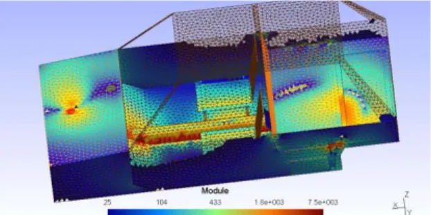
Fig. 6. Magnetization in A/m due to 100 A inside the whole power circuitry.
the width of the vehicle and are connected by 10 in parallel to form a horizontal plate. The entire pack is composed of eight plates divided in two groups; the first four plates are connected in parallel in the upper part, whereas the last four, also connected in parallel, are on the lower part of the battery. Then, each group is connected in series to obtain the good voltage (∼70 V) and energy (∼95 A·h).
This rear battery pack model and a part of the associated power cabling are added to the previous vehicle model (Fig. 3) to evaluate the magnetic field generated inside the car. Module of the magnetic field is computed (Fig. 5) along a centered line running from the rear to the front of the vehicle. This line is located 150 mm above the boot plate (i.e., 160 mm above the battery pack casing) and results are for a total current of 100 A. As expected, the ferromagnetic parts act as a magnetic shield. Peak-to-peak amplitude module is ∼43 µT when the battery pack is alone in the air and reduced to only 25 µT when the vehicle magnetic frame is present. Transverse field component is negligible on the line (amplitude is <2 µT without ferromagnetic material). The longitudinal field com-ponent is reduced by a factor three: from∼45 µT amplitude to 15µT. Vertical component is less shielded: from 43 to 25 µT. The other half battery pack is located in the motor com-partment and follows the same geometrics rules as for the rear one. The whole power circuitry is added to the vehicle model (Fig. 3) and Fig. 6 shows the material magnetization (in A/m) of the vehicle frame, due to a 100 A current flowing in the whole dc power circuit composed of the rear battery pack connected in series with the front battery pack through power cables (Version 01 in Fig. 4).
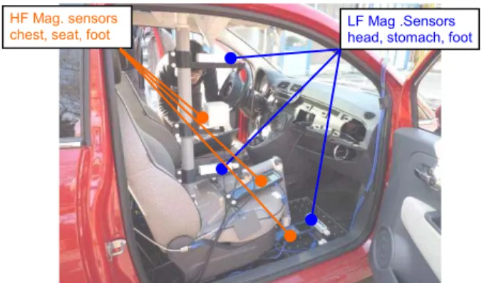
Fig. 7. Non-magnetic mannequin equipped with triaxes sensors. TABLE I
SENSORCHARACTERISTICS
TABLE II
ATTENUATIONFACTOR OF THEEARTHMAGNETICFIELDCOMPONENT
TABLE III
MAGNETICFIELDVARIATION DUE TOELECTRICCURRENTVARIATION
V. COMPARISON WITHMEASUREMENTS
As mentioned, some measurements have been made on-board the vehicle at different points: passenger location (see the measurement system inside the car on Fig. 7 and characteristics in Table I) and above the rear plate, near the rear battery.
For longitudinal and transverse directions, Table II lists the ratio between the field component inside the vehicle and the earth magnetic field. Table III lists the magnetic field variation due to the electric power current variation. For both cases, a good correlation is obtained between model and measurements.
A first forward model has been built and validated for mag-netostatic sources inside an electrical vehicle-like structure. Besides, this numerical model allows the study of any current distribution (e.g., the cell distribution inside the battery pack or power cables for connection) to minimize its magnetic stray fields inside the vehicle cabin.
Fig. 8. Magnetic induction created by different versions of the rear battery pack in which 100 A flows at 160 mm above the battery casing.
Fig. 9. Magnetization in A/m due to 100 A inside the modified power circuitry.
VI. APPLICATION TO THEPOWERCIRCUIT FIELDREDUCTION
In the studied vehicle, the original battery pack has been updated with Li-ion cells but the battery casing has been kept. On this casing, the battery connectors are separated and located on opposite lateral sides (refer to Version 01 in Fig. 4). As current goes into the battery on one side and goes out on the other side, cables create a quite large current loop that generates a magnetic field along the vertical direction. Therefore, a simple cabling modification should drastically reduce this field; both connectors are then gathered together into a single bipolar connector on one side (see Version 02 in Fig. 4). Electrical current cell distribution has also been modified to minimize their contribution because of electrical loops management. Li-Ion cells remain in series to form lines along the width of the vehicle but for each line, we tried to have its neighbors with an opposite electric current. Then, a line is connected in series with its direct neighbor below to form small electrical loop and obtain the good voltage. The final distribution is composed of 10 columns, each counts four vertical loops and the next column has its loops inverted. Every loop is connected in parallel to obtain the good energy.
Simulation is processed and the field is computed (Fig. 8) on the same line as in Section IV. Results are presented for the rear battery pack and a part of the associated power cabling, for a total current of 100 A and without any ferromagnetic part. Peak-to-peak amplitude is reduced to∼7.5 µT when power cables are gathered together and again divided by a factor three (∼2.5 µT) when electrical current cell distribution is also opti-mized (compared with 43µT with the original configuration). The same modification principle is applied to the front battery pack and cables. The whole modified power circuitry
(Version 02 in Fig. 4) is added to the vehicle model (Fig. 3) and Fig. 9 shows how the material magnetization (in A/m) of the vehicle frame has been also reduced when 100 A current flows in the whole optimized dc power circuit.
VII. CONCLUSION
Electric vehicle investigation allows to assess the contri-bution of each device found on-board (magnetic levels and frequencies dependencies).
A simple vehicle-like structure has been described with Flux3-D software to describe geometry and mesh, and simulation has been processed with an integral formulation. For both uniform (magnetic earth field) and nonuniform (created by electrical current distribution) magnetostatic field, the model has been validated because of the measurements. Thus, a useful modeling tool has been obtained that quantify the field inside an electrical vehicle by considering the shielding effect due to ferromagnetic parts with respect to on-board sources. This shielding effect may correspond to an attenuation of two or three.
We mainly focused on sources carrying high currents across the vehicle like the batteries and connecting conductors because our study has shown that they were mainly responsible for the higher fields inside the car. Finally, a complementary study of the electric current distribution demonstrates that simple rules lead to the strong minimization of the created magnetic field (∼18×).
This paper is a first important step in willing to characterize and model magnetic fields inside electric vehicle for exposure or CEM purposes. In further work, it may be applied to any new structure that develops strong current and special attention should be paid to the modeling of higher frequency ranges.
ACKNOWLEDGMENT
The authors would like to thank Institute Carnot for its support and for the contributions of CEA Liten and members of the EM safety project consortium. Further information can be found at: www.sintef.no/Projectweb/EM-Safety.
REFERENCES
[1] ICNIRP, “ICNIRP guidelines on limits of exposure to static magnetic fields,” Health Phys., vol. 96, no. 4, pp. 504–514, 2009.
[2] ICNIRP, “ICNIRP guidelines for limiting exposure to time-varying electric and magnetic fields,” Health Phys., vol. 99, no. 6, pp. 818–836, 2010.
[3] E. Karabetsos, et al., “EMF measurements in hybrid technology cars,” in Proc. 6th Int. Workshop Biol. Effects Electromagn. Fields, Bodrum, Turkey, Oct. 2010.
[4] F. M. Dietrich and W. L. Jacobs, “Survey and assessment of electric and magnetic field public exposure in the transportation environment,” Electric Research and Management, Inc., State College, PA, USA, Tech. Rep. PB99-130908, Mar. 1999.
[5] (2013). Flux 3D—Cedrat [Online]. Available: http://www.cedrat.com/ en/software/flux.html
[6] O. Chadebec, J.-L. Coulomb, and F. Janet, “A review of magnetostatic moment method,” IEEE Trans. Magn., vol. 42, no. 4, pp. 515–520, Apr. 2006.
[7] T.-S. Nguyen, J.-M. Guichon, O. Chadebec, P. Labie, and J.-L. Coulomb, “Ships magnetic anomaly computation with integral equation and fast multipole method,” IEEE Trans. Magn., vol. 47, no. 5, pp. 1414–1417, May 2011.
[8] J. Shin, B. Song, S. Lee, S. Shin, Y. Kim, G. Lung, et al., “Contactless power transfer systems for on-line electric vehicle (OLEV),” in Proc.