Publisher’s version / Version de l'éditeur:
Thin Solid Films, 426, February 1, pp. 221-231, 2003
READ THESE TERMS AND CONDITIONS CAREFULLY BEFORE USING THIS WEBSITE. https://nrc-publications.canada.ca/eng/copyright
Vous avez des questions? Nous pouvons vous aider. Pour communiquer directement avec un auteur, consultez la
première page de la revue dans laquelle son article a été publié afin de trouver ses coordonnées. Si vous n’arrivez pas à les repérer, communiquez avec nous à PublicationsArchive-ArchivesPublications@nrc-cnrc.gc.ca.
Questions? Contact the NRC Publications Archive team at
PublicationsArchive-ArchivesPublications@nrc-cnrc.gc.ca. If you wish to email the authors directly, please see the first page of the publication for their contact information.
NRC Publications Archive
Archives des publications du CNRC
This publication could be one of several versions: author’s original, accepted manuscript or the publisher’s version. / La version de cette publication peut être l’une des suivantes : la version prépublication de l’auteur, la version acceptée du manuscrit ou la version de l’éditeur.
For the publisher’s version, please access the DOI link below./ Pour consulter la version de l’éditeur, utilisez le lien DOI ci-dessous.
https://doi.org/10.1016/S0040-6090(03)00010-5
Access and use of this website and the material on it are subject to the Terms and Conditions set forth at
Pulsed laser deposition, characterization and thermochemical stability
of SrFeyCo1-yOx thin films
Tunney, Jim; Whitfield, Pamela; Du, Xiaomei; Post, Michael
https://publications-cnrc.canada.ca/fra/droits
L’accès à ce site Web et l’utilisation de son contenu sont assujettis aux conditions présentées dans le site LISEZ CES CONDITIONS ATTENTIVEMENT AVANT D’UTILISER CE SITE WEB.
NRC Publications Record / Notice d'Archives des publications de CNRC:
https://nrc-publications.canada.ca/eng/view/object/?id=7e9ee987-da84-44a4-83cf-c237e677acf5 https://publications-cnrc.canada.ca/fra/voir/objet/?id=7e9ee987-da84-44a4-83cf-c237e677acf5
0040-6090/03/$ - see front matter Crown Copyright 䊚 2003 Published by Elsevier Science B.V. All rights reserved. doi:10.1016/S0040-6090(03)00010-5
Pulsed laser deposition, characterization and thermochemical stability of
SrFe Co
y 1yyO thin films
xJames J. Tunney*, Pamela Whitfield, Xiaomei Du, Michael L. Post
Institute for Chemical Process and Environmental Technology, National Research Council of Canada, Montreal Road, Ottowa, Ontario, Canada K1A 0R6
Received 19 January 2002; received in revised form 22 October 2002; accepted 17 December 2002
Abstract
SrFe Coy 1yyO (ys0.0, 0.25, 0.50, 0.75, 0.90 and 1.0) thin films on sapphire substrates were prepared by laser deposition, andx
characterized by elemental analysis usingRutherford backscatteringspectroscopy, particle-induced X-ray emission and inductively coupled plasma-atomic emission spectroscopy, X-ray photoelectron spectroscopy, X-ray diffraction and scanningelectron microscopy. In order to determine the relative stability of the films at 500 8C, the films were subjected to both thermochemical oxidizingand reducingtreatments in 100% O and 2% H yargon gas mixtures, respectively. Thermochemical oxidizing treatments2 2
of the SrFe Coy 1yyO films resulted in dark-colored oxygen-rich films. Thermochemical reduction resulted in transparent yellow–x
brown films for the more iron-rich films, but not for the Co-rich films, which remained dark-colored. Fe-rich SrFe Coy 1yyO (ysx
0.50, 0.75 and 1.0) films exhibited the greatest degree of structural variation, resulting from the cubic perovskite™brownmillerite phase change upon reduction. Films with higher Co substitution showed smaller variations in the unit cell parameters. The SrCoO film was unstable under reducingconditions, with a Sr-enriched carbonate layer formingat the interface after exposurex
to ambient atmosphere. XRD measurements conducted in situ at 500 8C in both air and nitrogen gases confirmed that reversible structural changes occur in the film solely as a consequence of changing the surrounding gas composition, with the largest changes in lattice spacingoccurringfor the SrFe0.75Co0.25O and SrFe Co O films.x 0.5 0.5 x
Crown Copyright 䊚 2003 Published by Elsevier Science B.V. All rights reserved.
Keywords: Laser ablation; Sensors; Phase transitions; X-Ray diffraction
1. Introduction
Perovskite-type materials based on the composition SrFe Coy 1yyO have been shown to exhibit both fastx
oxide ionic conductivity and good electronic conductiv-ity w1–3x. This makes them suitable candidates for applications such as solid oxide fuel cell cathodes, oxygen membranes and sensor materials. For sensor applications, the materials should be in either the thin or thick film state. It has been demonstrated that thin films of these types of materials may be grown by pulsed laser deposition (PLD) w4–10x. Dependingon the deposition conditions, PLD can yield both dense and porous films with metal stoichiometry equal to that of the target material.
In a previous study it was shown that SrFe Coy 1yyOx
*Correspondingauthor. Fax: q1-613-991-2384.
thin films grown by PLD onto sapphire substrates exhibit promisinggas sensor functionality w4x. The cubic per-ovskite (CP)–brownmillerite (BM) phase transition for some of these films was attributed to enhanced gas sensitivity. The conditions of temperature and gas com-position at which this phase transition occurs could be controlled by choosingthe appropriate degree of iron and cobalt substitution in the SrFe Coy 1yyO structure. Itx
was also shown that some of these films exhibited a degree of temperature independence for the resistance response, while maintaining good gas sensitivity. This material property is important when tryingto minimize the influence of unstable temperatures on the perform-ance of a gas-sensing device. The present study focuses on the preparation and characterization of these films, and their thermochemical stability under reducingand oxidizingenvironments.
2. Experimental
2.1. Target preparation
Pellets of different SrFe Coy 1yyO compositions (ysx
0, 0.25, 0.5, 0.75, 0.9 and 1.0) were prepared by conventional ceramic preparation techniques. SrCO ,3
Fe O and Co O powders (2 3 3 4 99.99% pure on a metal basis) were mixed and ground together in the required quantities, followed by heat treatment at 1100 8C under either an argon or oxygen atmosphere. The samples were ground up again and the resulting black or brown powders were characterized by XRD. At this point, if the product was not single phase as evidenced by XRD, the product was further heated in oxygen, ground up and again examined by XRD. Once the single-phase product was obtained in the powdered form, the powder was pelletized and sintered at 1150 8C in oxygen. After XRD analysis confirmed the pellet to be single phase, the pellet could be used as the target material for the deposition of SrFe Coy 1yyOx films by pulsed laser deposition.
2.2. Film deposition
Preparation of 250–350-nm thin films of composition SrFe Coy 1yyO (ys0, 0.25, 0.5, 0.75, 0.9 and 1.0) wasx
carried out by PLD usinga Lambda Physik LPX305i, ls248 nm KrF excimer laser at an energy of 600 mJy pulse (fluence 1.5 Jycm ) and a frequency of 8 Hz. The2
substrate was (1102) single-crystal sapphire mounted¯ onto an alumina heater allowingfor deposition temper-atures up to 800 8C. The films were deposited for 20 min under a background oxygen pressure of 100 mtorr, followed by coolingat approximately 10 8Cymin in a background oxygen pressure of 400 torr. XRD analysis was performed on all PLD targets, both before and after deposition, in order to confirm that decomposition of the target material did not occur as a consequence of repeated laser exposure. Thickness determination was performed usinga Dektak IIA stylus profiler after shadow-maskingportions of the films.
2.3. Thermochemical treatments
The thermochemical stability of the films was tested under two separate environments, designed to simulate the operation of these materials as thin-film gas sensors under both thermochemical reducingand oxidizingenvi-ronments. The films were exposed to either flowing oxygen or to a 2% H yargon gas mixture (O2 2 1 ppm; H O2 3 ppm) at 500 8C in a tube furnace for 16 h, followed by coolingto room temperature at a rate of 1 8Cymin. Typically, a 1-cm SrFe Co2 O film was cut
y 1yy x
into two pieces, with one piece beingtreated in oxygen and the other in 2% H yArgon.2
2.4. XRD characterization
XRD characterization of the SrFe Coy 1yyO powders,x
targets and films at ambient temperatures was performed using a CuK Scintag XDS2000 Bragg–Brentano geom-a
etry diffractometer with a secondary-beam graphite monochromator. Powders were uniformly spread over a low-background Si holder, whereas pellets and films were placed on a low-background Si holder with the vertical displacement carefully adjusted with shims in order to minimize sample displacement errors.
2.5. SEM analysis
SEM analysis of the films was performed on a JEOL JSM 5300 instrument usinga 20-kV electron beam. Additional high-resolution FEG-SEM images were per-formed on selected films usinga Hitachi S-4700 instrument.
2.6. RBSyPIXE analysis
Rutherford backscattering (RBS) experiments were performed on SrFe Coy 1yyO films in a Tandetron systemx
usingHe alpha particles accelerated to 2.0 MeV using a van der Graaf accelerator. The detector angle was 1658, the target angle was 78 and a solid angle of 10.205 msr was used for all measurements with total acquisi-tions of 1–2 mC. RBS simulaacquisi-tions to estimate film stoichiometry were performed usingtheQUARKsoftware
program w11x. The RBS spectra for Co and Fe could not be resolved with RBS, but were instead determined by proton-induced X-ray emission (PIXE) analysis using protons accelerated to 1.5 MeV for a total acquisition of 2.0 mC.
2.7. ICP-AES analysis
Additional elemental analysis of the films was per-formed by inductively coupled plasma-atomic emission spectroscopy (ICP-AES) usinga Perkin Elmer Optima 3000 RV. The films were first completely dissolved in excess nitric acid before analysis and the resulting solutions analyzed usingcalibrated solutions for the followingspectral lines: Sr, 421.522 nm; Fe, 259.940 nm; and Co, 230.786 nm.
2.8. XPS analysis
X-Ray photoelectron spectroscopy (XPS) was per-formed on a Kratos Axis instrument usingmonochro-mated AlK radiation (1486.6 eV) usingan acceptancea
Table 1
Physical and chemical properties of the SrFe Coy 1yyO series of filmsx
Target Film Phase Orientation Film morphology Bulk film composition Film color composition thickness
Cracks Roughness ICP-AES RBSyPIXE 100% 2% H yAr2
(nm) O2
SrFeOx 300 CP (110) Faint, 1–2 mm 200 nm SrFe1.04Ox SrFe1.06Ox Black Transp. yellow SrFe Co O0.9 0.1 x 250 CP (110) Faint, 1–2 mm 200 nm SrFe0.95Co0.12Ox – Black Transp. yellow SrFe0.75Co0.25Ox 300 CP (110) Smooth 200 nm SrFe0.83Co0.25Ox SrFe0.75Co0.26Ox Black Brown–yellow SrFe Co O0.5 0.5 x 350 CP (200) 1–10 mm 200 nm SrFe0.53Co0.58Ox SrFe0.52Co0.57Ox Black Brown–black SrFe0.25Co0.75Ox 350 CP (200) Smooth 200 nm SrFe0.27Co0.82Ox SrFe0.23Co0.74Ox Black Black SrCoOx 350 Hex (201) 200-nm particles SrCo1.04Ox SrCo1.12Ox Black Black
CP, cubic perovskite lattice; Hex, hexagonal lattice determined for SrCoO . Preferential orientation of the film was determined by its mostx
intense reflection.
angle of 88, with the angle between the X-ray source and the detector beingfixed at 658. All samples were exposed to ambient atmosphere both before and after transfer to the spectrometer. An initial survey scan was taken to identify all elements present near the surface of the film. This was followed by a 15–30-s Ar sputter etch to pre-clean the surface, a second survey scan, and finally high-resolution spectra of the following XPS peaks: C 1s, O 1s, Sr 3d, Co 2p and Fe 2p. All peaks were referenced with respect to the amorphous carbon C 1s peak at bindingenergy of 285.0 eV. Atomic stoichiometries were calculated based on the integrated peak intensities of the high-resolution spectra after adjustingfor differences in relative sensitivity factors, estimated from the Kratos software.
2.9. In situ high-temperature XRD studies
X-Ray diffraction measurements were made at 500 8C under air and nitrogen in an Anton-Parr HTK1200 furnace. The furnace was mounted on a CuK Brukera ¨
D8 diffractometer equipped for parallel-beam geometry with primary and secondary double Gobel mirrors w12x.¨ The mirrors are very effective at removingCuK radi-b
ation, so there is no interference from sapphire Kb
reflections. The parallel-beam geometry renders the system insensitive to sample displacement errors in both sample mountingand due to thermal expansion. The system was calibrated for peak position usingthe NIST SRM 660a LaB standard. The films were heated to 5006
8C at a rate of 6 8Cymin and in ultra-high-purity (UHP) N2 (wO x 1 ppm; wH Ox 3 ppm), and allowed to2 2
equilibrate overnight. Once data collection was com-plete, the gas was switched to air, and the scan repeated once the film was left to equilibrate for approximately 1 h. UHP nitrogen was used rather than argon due to its weaker X-ray scattering. Lattice parameters were obtained from a full pattern usingthe Pawley method w13x with theTOPAS software package w14x. Peaks were
fitted with a pseudo-Voigt profile function, together with a correction for axial divergence.
3. Results and discussion
3.1. Film deposition and characterization
A series of films was deposited by PLD from six different target compositions (Table 1). The X-ray dif-fraction patterns of the SrFe Coy 1yyO targets were meas-x
ured both before and after laser deposition in order to confirm that decomposition of the bulk target material did not take place due to repeated laser pulses. It has previously been demonstrated that target decomposition duringthe course of the deposition process can lead to the formation of non-stoichiometric films w9x.
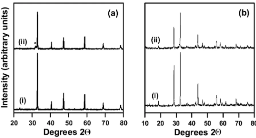
For all target materials employed, very little target decomposition was observed by XRD. Fig. 1 shows this for both the SrCoO and SrFeO targets. In the case ofx x
SrFeO , the presence of a low-intensity peak next to thex
(110) cubic perovskite reflection at 2Qs31.68 is attrib-uted to decomposition of the cubic perovskite phase w15x with approximate composition SrFeO2.9 to the oxygen-deficient SrFeO2.5brownmillerite phase w16x. In contrast, no significant change was observed for the SrCoO target, despite the more complex phase relationsx
for this system. SrCoO could be indexed to either ax
hexagonal SrCoO2.52 phase w17x that is structurally related to the oxygen-deficient 2H-BaNiO3 or to a rhombohedral Sr Co O structure (R) w18x. It has been2 2 5
demonstrated that as the high-temperature brownmiller-ite phase SrCoO2.5 cools in air, phase separation into SrCo O5 15 and Co O occurs, with powder neutron dif-3 4
fraction identifyingthe Sr Co O6 5 15 phase as rhombohe-dral and related to the 2H-hexagonal perovskite-type phase w19x. Despite some changes in bulk oxygen composition as evidenced by XRD, caused by the exposure to repeated laser ablation pulses, all the targets remained stoichiometric in terms of the SryM ratio (MsCo, Fe).
Fig. 1. XRD of (a) SrFeO and (b) SrCoO targets (i) before and (ii) after deposition. * indicates the presence of brownmillerite phase.x x
Under the deposition conditions employed, preferen-tially oriented polycrystalline films were obtained with thickness of between 250 and 350 nm. Stylus profiling also showed that the film thickness could vary through the 1–2-cm surface of the film by as much as 10–2
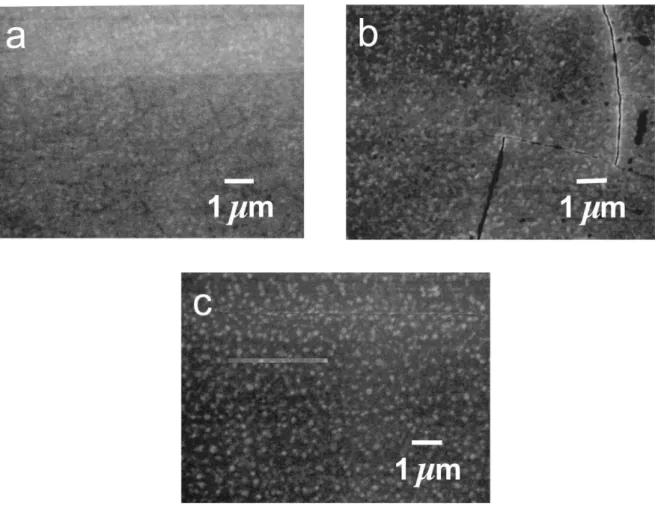
20%. The as-deposited films appeared shiny black or dark brown. SEM analysis of the films showed varying morphology, from cracks to various degrees of graininess (Table 1). Three typical examples of film morphology are shown in Fig. 2. The morphology of all films except SrCoO did not change as a result of the subsequentx
thermochemical oxidizingand reducingsteps (Section 3.2).
The SrFe Coy 1yyO (ys0.25, 0.5, 0.9 and 1.0) filmsx
were all indexed to the cubic perovskite phase and were either preferentially (110)-oriented for ys0.5, 0.75, 0.9 and 1.0 or (200)-oriented for ys0.25 and 0.5. Depend-ingon small variations in deposition conditions, such as the deposition temperature, SrFe Co O could either0.5 0.5 x
adopt a (110) or a (200) preferential orientation. SrCoO films exhibited (201) preferential orientationx
with respect to the hexagonal phase w17x.
The bulk stoichiometry of the films was independently evaluated by both RBS-PIXE and ICP-AES and values were consistent to within 10% of the expected metal stoichiometry (Table 1). The oxygen stoichiometry of the films could not be determined usingthese tech-niques. The RBS and PIXE spectra for a SrFe Co O film are shown in Fig. 3. Cobalt and iron0.5 0.5 x
could not be discriminated usingRBS alone, so for films containingboth Co and Fe, PIXE spectra were obtained. Some of the films showed evidence of varia-tions in metal stoichiometry with film depth. This variation could be modeled with the QUARK software
usingeither two or three layers with different SryM stoichiometry. The compositions shown in Table 1 are the overall stoichiometry as determined over the entire thickness of the films.
For the SrFe Co O film (Fig. 3a), the simulation0.5 0.5 x
was modeled usingtwo SrFe Coy 1yyO layers with dif-x
feringstoichiometry. The layer closest to the surface was 63 nm thick with SryMs0.78, while the second was 290 nm thick with SryMs0.95. The reasons for the inhomogeneity in some of these films is not fully understood, but may be related to the formation of a surface segregated phase at the perovskite interface w20– 22x.
Deconvolution and integration of the Fe and Co Ka
and K X-ray peaks shown in the PIXE spectra in Fig.b
3b, followed by adjustingfor the relative sensitivity factors, yielded a CoyFe ratio of 1.1 compared to an expected value of 1.0. Comparison of the bulk film stoichiometry obtained from RBSyPIXE and ICP-AES shows that the values are consistent to within 10%, with most films showinga slight CoqFe enrichment with respect to Sr. It was estimated that the accuracy of the data obtained by both these techniques is 10%, so this apparent CoqFe enrichment may not be significant.
3.2. Thermochemical stability of films
The stability of the SrFe Coy 1yyO films at tempera-x
tures typical for gas sensor operation (500 8C) were investigated in both oxidizing (100% O ) and reducing2
(2% H in argon) environments (Section 2.3. All films2
exposed to oxygen at 500 8C remained black or black– brown, whereas some of the films exposed to 2% H in2
argon turned yellow or yellow–brown. This change in color has previously been reported for SrFeO films andx
is indicative of a change from the oxygen-rich cubic perovskite phase to the oxygen-deficient brownmillerite phase w23x. In particular, the iron-rich films, SrFeO ,x
SrFe Co O and SrFe0.9 0.1 x 0.75Co0.25O , all showed colorx
changes to yellow or light brown as a result of the reducingtreatment (Table 1).
The XRD patterns for the films also showed pro-nounced changes after the two different thermochemical
Fig. 2. SEM images of as-deposited films showing different types of film morphology: (a) SrFeO ; (b) SrFex 0.50Co0.50O ; and (c) SrCoO .x x
Fig. 3. (a) RBS and (b) PIXE spectra of a 300-nm SrFe Co O film deposited on sapphire.0.5 0.5 x
treatments (Figs. 4 and 5). Thermal treatments in oxygen resulted in little structural change from the as-deposited films. The SrFe Coy 1yyO (ys0.25, 0.5, 075, 0.9 andx
1.0) films were all indexed to the cubic perovskite phase, although the presence of a tetragonal perovskite phase should not be ruled out because of insufficient resolution w5,24x. The degree and type of preferential
orientation, whether (110) or (200), did not change from the as-deposited films.
Upon exposure to 2% H in argon, significant struc-2
tural changes occurred, and the XRD patterns could be indexed to the brownmillerite state w16,25x. This was evidenced by the marked shift of the (110) and (200) cubic perovskite peaks to lower 2Q angle, and the
Fig. 4. XRD for films after treatment in 100% O at 500 8C for 162 h: (a) SrFeO ; (b) SrFex 0.50Co0.50O ; and (c) SrCoO . Note that therex x
is an interference from a CuK peak of the sapphire substrate at 2Qsb 47.28, which overlaps with the (200) CP peak.
Fig. 5. XRD for films after treatment in 2% H yAr at 500 8C for 162 h: (a) SrFeO ; (b) SrFex 0.50Co0.50O ; and (c) SrCoO . The sharp peakx x
at 2Qs47.28 is from a CuK peak of the sapphire substrate.b
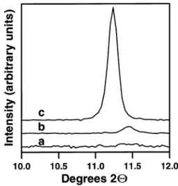
Fig. 6. XRD for SrFe0.50Co0.50O films showing evolution of the high-x
angle reflection at 2Qs11.28 attributable to the formation of a super-cell with ds2a (where a is the lattice parameter of the perovskitep p unit cell): (a) as-deposited film; (b) after exposure to 100% O at2 500 8C; and (c) after exposure to 2% H yAr at 500 8C.2
appearance of additional peaks consistent with a larger unit cell of lower symmetry. A strikingexample is the SrFe Co O film, which shows the appearance of an0.5 0.5 x
intense peak at 2Qs11.28 after the thermochemical reducingstep (Fig. 6c). Similar results were obtained for both SrFe0.75Co0.25O and SrFex 0.25Co0.75O films.x
The SrFeO film also showed a weak reflection at 2Qsx
11.28. These peaks are attributed to the (020) reflection of the larger brownmillerite structure w16,25x.
For the SrFe Co O film, a less intense peak at0.5 0.5 x
2Qs11.58 was observed after the thermochemical oxi-dation treatment (Fig. 6b). This indicates that perovski-te-type supercells may form, even after thermochemical oxidizingtreatments, and matches the observation that very weak reflections at ds14.31, 7.7 and 5.34 A were˚ observed for cubic SrFe Co O powder w26x, sug-0.5 0.5 3
gesting possible transitions to lower symmetry. Indica-tions of such expanded unit cells for SrFeO w5,24,27xx
and SrFe Co O w28,29x have previously been report-0.8 0.2 x
ed and attributed to oxygen vacancy ordering, forming, for example, SrFeO2.86 tetragonal and SrFeO2.73 ortho-rhombic perovskite-type structures w24x. Cation ordering between the Fe and Co atoms may also result in an expanded unit cell, formingan ordered double perovskite of the type that has been described for SrFe Mo O0.5 0.5 3
w30x.
The SrCoO film remained preferentially (210)-ori-x
ented, and the XRD peaks shifted only slightly to a higher 2Q angle upon exposure to 2% H in argon. In2
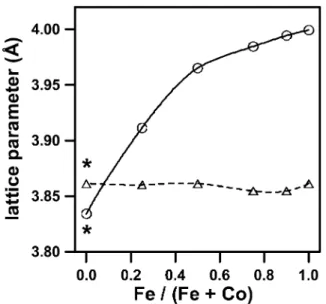
contrast to all the other films, this corresponds to a slight contraction of the unit cell. This is illustrated in Fig. 7 for the SrFe Coy 1yyO series of films, whichx
shows the variation of the equivalent cubic unit cell parameter, a, derived from the (110) cubic perovskite peak or its equivalent. In all cases except for SrCoO ,x
the unit cell parameter, a, increased as a result of the thermochemical reduction treatment. This difference was greatest for SrFeO , and decreased with increasing Cox
content in the film. This structural trend is consistent with sensor functionality observations, which showed that the iron-rich films in the SrFe Coy 1yyOx series exhibited significantly greater changes in conductivity at 500 8C for the range of oxygenynitrogen gas com-positions 10y5FpwO xF1 atm w4x. Moreover, this also
2
matches the results obtained usingin situ XRD (Section 3.3).
XPS measurements of the SrFe Coy 1yyO series ofx
films after both thermochemical oxidizingand reducing conditions showed that for all films except SrCoO ,x
Fig. 7. Plot showing the variation of the lattice parameter, a, for the SrFe Coy 1yyO series of films at ambient temperature, after thermo-x
chemical treatments in 100% O (dashed line) and 2% H yAr (solid2 2 line) gas mixtures. The equivalent cubic lattice parameter, a, was derived from the (110) cubic peak or its equivalent lower symmetry peak(s) for the brownmillerite or hexagonal structure (SrCoO ). *Thex
SrCoO perovskite phase is not stable at room temperature (see textx
for details).
Fig. 8. High-resolution O 1s XPS spectra for: (a) SrFeO ; (b)x
SrFe0.50Co0.50O ; and (c) SrCoO after thermochemical treatments atx x
500 8C in 100% O (solid lines) and 2% H yAr (dashed lines). A2 2 15-s Arqsputter etch was used to pre-clean the surface.
Fig. 9. High-resolution Sr 3d XPS spectra of: (a) SrFeO ; (b)x
SrFe0.50Co0.50O ; and (c) SrCoO after thermochemical treatments atx x
500 8C in 100% O (solid lines) and 2% H yAr (dashed lines). A2 2 15-s Arqsputter etch was used to pre-clean the surface.
there were only minor differences in the XPS O 1s, Sr 3d, Co 2p and Fe 2p spectra. Two peaks are observed for the O 1s XPS region (Fig. 8), one at 529.5 eV and the other at a higher binding energy between 531 and 532 eV. The higher-energy O 1s peak for perovskite surfaces is attributed to surface-bound oxygen species, possibly oxygen weakly bound on the surface, surface hydroxyls, or to a surface metal–O bond, while the lower-energy peak is attributed to lattice oxygen w6,31– 38x. Moreover, the higher-binding-energy peaks were much more sensitive to Arq etchingtreatment than the lower-energy peak, thus supporting this assignment.
The Sr 3d XPS region (Fig. 9) shows a doublet, 3d5y2 and 3d3y2, at 133 and 135 eV, respectively. These assignments are consistent with the chemical shifts reported for other similar Sr-containingperovskites w32–34,36x. Although no curve fitting was performed, these doublets are likely comprised of more than one contribution, assigned to Sr present in the bulk and at surface sites as SrO and SrCO w32x.3
Both the Fe 2p and Co 2p spectral regions show at least one set of doublets between 700 and 735, and 770 and 810 eV, respectively. These showed small spectral changes after different thermochemical treatments, but were difficult to interpret due to the closeness of peaks associated with different oxidation states of iron and cobalt, and the presence of satellite shake-up lines associated with the paramagnetic Fe(III) and Co(III) states w39x.
The thermochemical reducingtreatment of SrCoO ,x
in contrast to the other films, caused surface changes resultingin notably different XPS spectra (Fig. 8c, Fig. 9c, Fig. 10b). It is proposed that prolonged exposure to the reducing gas mixture of 2% H in argon at 500 8C2
resulted in decomposition of the surface of the film to form SrO. SrO then reacted with CO from the ambient2
air to form SrCO3 This type of behavior has been reported for La Sr CoO (LSCO) perovskite mem-0.3 0.7 x
branes duringoxygen permeation experiments w31x. In this case, a 10–15-nm surface SrO layer was formed by reduction of the La Sr CoO phase followingpro-0.3 0.7 x
longed exposure to a 1.4% O in helium gas mixture at2
Fig. 10. C 1s XPS spectra for SrCoO after thermochemical treatmentx
at 500 8C in 2% H yAr (a) before and (b) after a 30-s Arqetch. 2
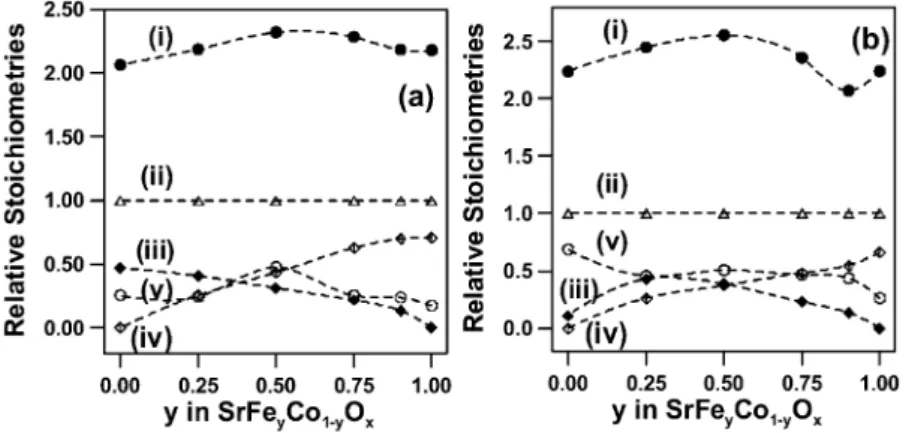
Fig. 11. Plot showing the relative surface stoichiometries of the SrFe Coy 1yyO series of films after thermochemical treatments at 500 8C in (a)x
100% O and (b) 2% H yAr gas mixtures: (i) d oxygen; (ii) D strontium; (iii) e iron; (iv) ⽧ cobalt; and (v) s carbon. A 15-s Arqsputter
2 2
etch was used to pre-clean the surface prior to chemical analysis by XPS.
CO2 reacted with SrO to form SrCO , which was3
identified by XPS.
Evidence for this is also supported by the XPS O 1s, Sr 3d and C 1s spectral regions. For the SrCoO film,x
an intense higher-binding-energy O 1s peak is observed at 531.7 eV (Fig. 8c) after the thermochemical reducing treatment. This chemical shift is consistent with that expected for a carbonate oxygen w32,39x. The intensity of the lower-energy 529.5-eV peak is much smaller than for the film treated under oxidizingconditions, indicat-ingthat the dominant surface oxygen species is no longer the lattice oxygen associated with the perovskite phase. The Sr 3d doublet (Fig. 9c) also showed a shift to higher binding energy with the Sr 3d5y2peak located at 133.6 eV, which approaches the 133.2-eV value reported for SrCO w39x. Furthermore, a high-energy C3
1s XPS peak at 290 eV (Fig. 10) also matches the 289.5-eV peak reported for SrCO w39x. A 30-s Arq
3
surface etch causes the amorphous carbon peak at 285.0
eV, which is associated with carbonaceous surface con-tamination, to decrease in intensity. In contrast, the intensity of the carbonate peak at 290 eV is almost unaffected. The surface CO2y XPS peak assignments
3
for the O 1s, C 1s and Sr 3d spectral regions are similar to those made for a series of La1yxSr -based perovskite-x
type oxides w32x. These observations indicate that the SrCoO film has undergone substantial surface decom-x
position to form a carbonate species after exposure to ambient atmosphere.
When the relative surface stoichiometry values for the SrFe Coy 1yyO series of films obtained from XPS arex
plotted, a number of trends are apparent (Fig. 11). First of all, the surface of all films appear to be enriched in strontium, compared to their bulk stoichiometry (Table 1). This may be the result of the formation of a surface segregated phase, which has been described elsewhere for the perovskite interface w20–22,31,33,38,40,41x. However, it is noted that calibrated reference samples were not used for the determination of the surface stoichiometry of these films by XPS. The strontium enrichment of the surface contrasts with the surface metal enrichment observed for the as-deposited SrFe Co O0.5 0.5 x film by RBS (Section 3.1). This is probably a consequence of the post-deposition thermo-chemical treatments, which may change the relative metal concentrations at the surface w20– 22,31,33,38,40,41x.
The Co and Fe stoichiometry changes as expected across the SrFe Coy 1yyO series of films except for thex
SrCoO film after thermochemical reduction (Fig. 11b).x
This film showed much lower than expected Co content, resultingfrom the formation of a strontium-enriched carbonate phase at the surface. Moreover, the carbon content for this film was anomalously high, consistent with the presence of such a carbonate phase.
FEG-SEM images of the SrCoO films after oxidizingx
Fig. 12. SEM images of the SrCoO film after thermochemical treat-x
ments at 500 8C in (a) 100% O and (b) 2% H yAr gas mixtures.2 2
Fig. 13. XRD patterns of: (a) SrFeO ; (b) SrFex 0.75Co0.25O ; (c)x
SrFe0.50Co0.50O ; (d) SrFex 0.25Co0.75O ; and (e) SrCoO films taken inx x
situ at 500 8C in UHP N (upper dashed lines) and air (bottom dark2 lines).
changes in the morphology of the films (Fig. 12). The SrCoO film exposed to oxygen gas at 500 8C showedx
a polycrystalline film with grain size dimensions ranging between 20 and 150 nm. After the thermochemical reducing treatment, substantial grain growth occurred, with large grains between 250 and 500 nm appearing. Smaller grains 100 nm were found between and under these larger grains. The two different grain types suggest that film decomposition has occurred, with two separate phases beingpresent.
3.3. In situ XRD study of films
The chemical sensitivity of the SrFe Coy 1yyO filmsx
is due in large part to the reversible physical and structural changes that occur at elevated temperatures ( 250 8C) when the films are exposed to different gas mixtures w4x. Accordingly, the structural changes in the SrFe Coy 1yyO series of films upon changing gas com-x
position from air to nitrogen were examined in situ at 500 8C by XRD. The temperature of 500 8C was selected as a typical operation temperature for this sensor material.
All films except SrCoO showed evidence of unit cellx
expansion upon changing from air to nitrogen exposure (Fig. 13, Table 2). This effect was most pronounced for the SrFe0.75Co0.25O and SrFe Co O films and couldx 0.5 0.5 x
best be observed by examiningthe changes in the (110) and (200) cubic or slightly distorted tetragonal perov-skite peaks near 2Qs328 and 468, respectively. The shift towards lower 2Q angles for these peaks and the appearance of additional peaks, some of which were as low as 2Qs11.28, were all consistent with the transfor-mation in structure from a cubic perovskite to brown-millerite with ordered oxygen vacancies w4,5,24,27x.
In contrast, changing from air to nitrogen exposure caused slight shifts of the XRD peaks towards higher 2Q angles for the SrCoO film. This is consistent withx
the decrease in lattice parameters observed for this film after the more severe thermochemical reducingtreatment (Section 3.2).
The lattice parameters for the films exposed to the two gas mixtures (Table 2) indicated that a phase change from tetragonal perovskite (TP) to brownmillerite (BM) occurred for SrFeO ,x SrFe0.75Co0.25Ox and SrFe Co O . The TP phase was observed for the films0.5 0.5 x
exposed to air, whereas the BM phase was observed for the films exposed to nitrogen. The TP phase, which is a distortion of the higher-symmetry CP phase, was found to provide better XRD refinements compared to the CP phase, although the film is probably an equilibrium mixture of both the CP and TP phases. The TP phase has previously been shown to exist in equilibrium with the CP phase for the bulk SrFeO system at temperaturesx
Table 2
Reversible structural changes occurring in situ at 500 8C, as determined by XRD, for the SrFe Coy 1yyO series of films resultingfrom changes inx
gas composition
Composition Gas Unit cell Lattice parameters (A)˚ Normalized
a b c unit cell volume (A )3 ˚ SrFeOx Air TP 3.889 (4) 3.908 (2) 59.11 (10) SrFeOx N2 BMa 5.657 (2) 5.622 (2) 5.525 (3) 61.03 (4) SrFe0.75Co0.25Ox Air TP 3.8870 (7) 3.9063 (9) 59.02 (2) SrFe0.75Co0.25Ox N2 BM 5.660 (2) 15.926 (7) 5.563 (3) 62.68 (5) SrFe Co O0.5 0.5 x Air TP 3.9030 (2) 3.9146 (4) 59.63 (1) SrFe Co O0.5 0.5 x N2 BM 5.678 (4) 15.937 (8) 5.640 (3) 63.79 (6) SrFe0.25Co0.75Ox Air BMb 5.636 (3) 15.581 (7) 5.523 (3) 60.63 (6) SrFe0.25Co0.75Ox N2 BMb 5.652 (4) 15.64 (1) 5.501 (4) 60.80 (8) SrCoOx Air ORc 2.9804 (8) 3.0079 (10) 14.298 (6) 64.09 (4) SrCoOx N2 ORc 2.9700 (9) 3.0054 (9) 14.241 (7) 63.56 (5)
TP, tetragonal perovskite lattice; BM, brownmillerite lattice; OR, orthorhombic lattice. Film is likely a mixture of brownmillerite and tetragonal perovskite phases. a
Film is a mixture of brownmillerite and rhombohedral phases b
Refinements usingthe hexagonal w17x and rhombohedral w42x cells showed larger residual errors than those based on the OR structure. c
lower than 500 8C for oxygen stoichiometry 2.86 x
2.97 w5,24x. Two-phase regions containing both cubic perovskite and brownmillerite for bulk powders have been reported for both the SrFeOx w24,27x and SrFe Co O w28x systems. Accordingto the phase0.8 0.2 x
diagrams reported for these systems, this two-phase region exists over large ranges of oxygen stoichiometry at 500 8C. For SrFeO at 500 8C this region is boundedx
by 2.56 x 2.66 and corresponds to an equilibrium gas composition of pwO xs10y4 atm. For SrFe Co O it
2 0.8 0.2 x
is necessary to extrapolate the temperature to 500 8C, since the phase diagram is only given from 550 to 900 8C. When this was carried out, the two-phase region was estimated to occur in the range 2.49 x 2.63 and corresponds to an oxygen partial pressure slightly less than 0.2 atm. The presence of these perovskite–brown-millerite two-phase regions has been shown to be asso-ciated with enhanced oxygen gas sensitivity w4,23x.
The SrFe0.25Co0.75O film was indexed to the BMx
phase for both air and nitrogen exposure, despite the uncertainty due to the presence of trace amounts of a SrCoO -type rhombohedral phase w42x, identified by ax
weak reflection at 2Qs28.38. The presence of the brownmillerite phase for both air and nitrogen exposure at 500 8C can be explained on the basis of the high-temperature phase diagram published for SrFe Co O w28x, which indicates that equilibration0.8 0.2 x
in air at 500 8C should favor the brownmillerite struc-ture. As a result, no phase change was detected. Like-wise, the SrCoO film was indexed to an orthorhombicx
unit cell for both gas exposures with no phase transitions occurring.
Films that exhibited TP™BM phase transformations also showed larger changes in the normalized unit cell
volume wunit cell volume per Sr(Fe,Co)O formula unitx.x
For example, SrFe Co O showed a 7.0% unit cell0.5 0.5 x
volume expansion as a result of changing the gas composition from air to nitrogen. In contrast, SrFe0.25Co0.75O showed only a 0.3% expansion of thex
equivalent unit cell volume upon changing from air to nitrogen, and SrCoO actually showed a 0.8% contrac-x
tion. However, the SrCoO system is complicated byx
the instability of the 1:1 perovskite composition, which forms Sr Co O6 5 15and Co O in air upon cooling w19x.3 4
4. Conclusions
Non-stoichiometric SrFe Coy 1yyO films of differentx
composition can be prepared by pulsed laser deposition on sapphire substrates. The as-deposited polycrystalline films were indexed to either the cubic perovskite (SrFe Coy 1yyO ; ys1.0, 0.9, 0.75, 0.5 and 0.25) orx
hexagonal (SrCoO ) phases, and were all found tox
exhibit some degree of preferential orientation. Elemen-tal analyses by both RBSyPIXE and ICP-AES were consistent and indicated a slight (CoqFe) enrichment for some of the films.
Thermochemical treatments at 500 8C in both oxidiz-ing (100% O ) and reducoxidiz-ing (2% H in Ar) gas mixtures2 2
showed all the films except SrCoO were stable underx
these conditions, despite undergoing significant reversi-ble structural changes resulting from the changing oxy-gen stoichiometry in the films. Surface decomposition of the SrCoO film to form a Sr-enriched carbonatex
layer was confirmed by XPS and SEM analysis. In situ XRD measurements under conditions expected for sensor operation, performed on the films at 500 8C, confirmed that reversible structural changes occurred in
the SrFe Coy 1yyO series of films upon changing gasx
composition from air to nitrogen. This structural varia-bility is important, since it forms the basis for bulk oxygen chemical sensors exhibiting high sensitivity.
Acknowledgments
The authors would like to thank G. Pleizier for the XPS and SEM analysis, J. Fraser for FEG-SEM analysis, V. Boyko for ICP-AES analysis, and Dr W. Lennard and Dr Joon Kon Kim at the University of Western Ontario Surface Science Facility for the RBS and PIXE analysis.
References
w1x Y. Teraoka, H.M. Zhang, S. Furukawa, N. Yamazoe, Chem. Lett. 1985 (1985) 1743.
w2x Y. Teraoka, H.M. Zhang, K. Okamoto, N. Yamazoe, Mater. Res. Bull. 23 (1988) 51.
w3x V.V. Kharton, E.N. Naumovitch, A.V. Nikolaev, J. Membrane Sci. 111 (1996) 149.
w4x J.J. Tunney, M.L. Post, X. Du, D. Yang, J. Electrochem. Soc. 149 (2002) H113.
w5x M.L. Post, B.W. Sanders, P. Kennepohl, Sensors Actuators B 13y14 (1993) 272.
w6x Y. Yu, Y.F. Chen, Z.G. Liu, L. Sun, S.B. Xiong, N.B. Ming, Z.M. Ji, J. Zhou, Appl. Phys. A: Mater. Sci. Process. 64 (1997) 69.
w7x H. Tanaka, N. Matsuoka, S. Oki, S. Gohda, T. Kawai, Thin Solid Films 326 (1998) 51.
w8x X. Chen, N.J. Wu, D.L. Ritums, A. Ignatiev, Thin Solid Films 342 (1999) 61.
w9x D. Waller, L.G. Coccia, J.A. Kilner, I.W. Boyd, Solid-State Ionics 134 (2000) 119.
w10x C. Zhang, H. Deng, J. Varon, B. Abeles, Y. Yang, A.Q. Pham, A.J. Jacobson, in: G.-A. Nazri, J.-M. Tarascon, M. Schreiber (Eds.), Solid-State Ionics IV, Boston, USA, 28 November–1 December 1994, Mater. Res. Soc. Symp. Proc. 369 (1995) 401.
w11x W.N. Lennard, C.P. McNorgan, Quantitative Analysis of Ruth-erford Kinematics Simulation Software, University of Western Ontario, Interface Science Western, London, ON, Canada (2001).
w12x M. Schuster, H. Gobel, J. Phys. D: Appl. Phys. 28 (1995)¨ A270.
w13x G.S. Pawley, J. Appl. Crystallogr. 14 (1981) 357.
w14x Bruker AXS, TOPAS V2.0: General Profile and Structure Analysis Software for Powder Diffraction Data, User Manual, Bruker AXS, Karlsruhe, Germany, 2000.
w15x Powder Diffraction File, Card 40-0905, Joint Committee on Powder Diffraction Standards, ASTM, Philadelphia, PA, 1967. w16x Powder Diffraction File, Card 17-0932, Joint Committee on Powder Diffraction Standards, International Center for Diffrac-tion Data, Newton Square, PA, 1997.
w17x Powder Diffraction File, Card 40-1018, Joint Committee on Powder Diffraction Standards, International Center for Diffrac-tion Data, Newton Square, PA, 1997.
w18x J. Rodriguez, J.M. Gonzalez-Calbet, Mater. Res. Bull. 21 (1986) 429.
w19x W.T.A. Harrison, S.L. Hegwood, A.J. Jacobson, Chem. Com-mun. 1995 (1995) 1953–1954.
w20x G. Horvath, J. Gerblinger, H. Meixner, J. Giber, Sensors Actuators B 32 (1996) 93.
w21x S.B. Desu, D.A. Payne, J. Am. Ceram. Soc. 73 (1990) 3391. w22x S.B. Desu, D.A. Payne, J. Am. Ceram. Soc. 73 (1990) 3398. w23x J.J. Tunney, M.L. Post, J. Electroceram. 5 (2000) 63–69. w24x Y. Takeda, K. Kanno, T. Takada, O. Yamamoto, M. Takano,
N. Nakayama, Y. Bando, J. Solid-State Chem. 63 (1986) 237. w25x Powder Diffraction File, Card 30-0226, Joint Committee on Powder Diffraction Standards, International Center for Diffrac-tion Data, Newton Square, PA, 1997.
w26x Powder Diffraction File, Card 46-0335, Joint Committee on Powder Diffraction Standards, International Center for Diffrac-tion Data, Newton Square, PA, 1997.
w27x J. Mizusaki, M. Okayasu, S. Yamauchi, K. Fueki, J. Solid State Chem. 99 (1992) 166.
w28x L.M. Liu, T.H. Lee, L. Qiu, Y.L. Yang, A.J. Jacobson, Mater. Res. Bull. 31 (1996) 29.
w29x L. Qiu, T.H. Lee, L.M. Liu, Y.L. Yang, A.J. Jacobson, Solid-State Ionics 76 (1995) 321.
w30x F.S. Galasso, Structure, Properties and Preparation of Perov-skite-Type Compounds, Pergamon, London, 1969.
w31x R.H.E. van Doorn, H.J.M. Bouwmeester, A.J. Burggraaf, Solid-State Ionics 111 (1998) 263.
w32x P.A.W. van der Heide, Surf. Interface Anal. 33 (2002) 414. w33x P.A.W. van der Heide, Surf. Sci. 473 (2001) 59.
w34x M. Machkova, N. Brashkova, P. Ivanov, J.B. Carda, V. Kozhu-kharov, Appl. Surf. Sci. 119 (1997) 127.
w35x N. Gunasekaran, S. Rajadurai, J.J. Carberry, N. Bakshi, C.B. Alcock, Solid-State Ionics 73 (1994) 289.
w36x A.E. Bouquet, P. Chalker, J.F. Dobson, P.C. Healy, S. Myhra, J.G. Thompson, Physica C 160 (1989) 252.
w37x K. Tabata, I. Matsumoto, S. Kohiki, J. Mater. Sci. 22 (1987) 1882.
w38x J.A. Marcos, R.H. Buitrago, E.A. Lombardo, J. Catal. 105 (1987) 95.
w39x J.F. Moulder, W.F. Stickle, P.E. Sobol, K.D. Bomben, Handbook of X-Ray Photoelectron Spectroscopy, Perkin Elmer Corpora-tion, Physical Electronics Division, Eden Prairie, Minnesota, 1992.