Publisher’s version / Version de l'éditeur:
Journal of Fire Protection Engineering, 14, November 4, pp. 265-281, 2004-11-01
READ THESE TERMS AND CONDITIONS CAREFULLY BEFORE USING THIS WEBSITE.
https://nrc-publications.canada.ca/eng/copyright
Vous avez des questions? Nous pouvons vous aider. Pour communiquer directement avec un auteur, consultez la
première page de la revue dans laquelle son article a été publié afin de trouver ses coordonnées. Si vous n’arrivez pas à les repérer, communiquez avec nous à [email protected].
Questions? Contact the NRC Publications Archive team at
[email protected]. If you wish to email the authors directly, please see the first page of the publication for their contact information.
NRC Publications Archive
Archives des publications du CNRC
This publication could be one of several versions: author’s original, accepted manuscript or the publisher’s version. / La version de cette publication peut être l’une des suivantes : la version prépublication de l’auteur, la version acceptée du manuscrit ou la version de l’éditeur.
For the publisher’s version, please access the DOI link below./ Pour consulter la version de l’éditeur, utilisez le lien DOI ci-dessous.
https://doi.org/10.1177/1042391504044161
Access and use of this website and the material on it are subject to the Terms and Conditions set forth at
Thermal decomposition products from fire suppression with
HFC-227ea in an electronic facility
Kim, A. K.; Su, J. Z.
https://publications-cnrc.canada.ca/fra/droits
L’accès à ce site Web et l’utilisation de son contenu sont assujettis aux conditions présentées dans le site LISEZ CES CONDITIONS ATTENTIVEMENT AVANT D’UTILISER CE SITE WEB.
NRC Publications Record / Notice d'Archives des publications de CNRC: https://nrc-publications.canada.ca/eng/view/object/?id=135bb627-046e-4eb5-b137-ef38b9b7396c https://publications-cnrc.canada.ca/fra/voir/objet/?id=135bb627-046e-4eb5-b137-ef38b9b7396c
Thermal decomposition products from fire
suppression with HFC-227ea in an electronic facility
Kim, A.K.; Su, J.
NRCC-46778
A version of this document is published in / Une version de ce document se trouve dans :
Journal of Fire Protection Engineering, v. 14, no. 4, Nov. 2004, pp. 265-281
doi:
10.1177/1042391504044161
Thermal Decomposition Products from Fire Suppression with HFC-227ea in an
Electronic Facility
ANDREW K. KIM* AND JOSEPH SU
Fire Risk Management Program Institute for Research in Construction National Research Council of Canada
Ottawa, Ontario, K1A 0R6, Canada
ABSTRACT
A study was undertaken to address concerns of corrosion in an electronic environment after fire
suppression using HFC-227ea (C
3F
7H). Fire suppression using halocarbon agents, such as
HFC-227ea, can produce thermal decomposition products, such as hydrogen fluoride (HF), which may
cause potential corrosion problem to electronic equipment. In this study, full-scale experiments
were conducted in a simulated electronic equipment room using 6 steel cabinets under various
ventilation conditions. An in-cabinet cable fire was used in the tests as a fire source and
HFC-227ea was used to suppress the fire. FTIR spectrometers were used to measure the gases in the
cabinets and room. The test results showed that the ventilation conditions of the cabinet affected
the fire extinguishment times for the fire in the cabinet, and therefore the amount of HF
generation. In the open cabinet cable fire test, the concentration of HF was below 100 ppm in
the fire cabinet. In the closed cabinet cable fire test, the maximum concentration of the HF
reached 800 ppm in the fire cabinet. The migration of gaseous by-products from the fire cabinet
to the adjacent non-fire cabinets was minimal. A large heptane pool fire test was also conducted;
the maximum HF concentration in the room reached 3900 ppm. The non-fire open cabinet
reached a peak HF concentration of 3800 ppm, whereas the ventilated and closed cabinets
reached a peak HF concentrations of 1800 ppm and 500 ppm, respectively.
Key words: thermal decomposition, halocarbon, fire suppression, electronic facility
INTRODUCTION
Fire suppression using halocarbon agents can produce gas products, such as hydrogen fluoride (HF)[1-3]. In an electronic environment, potential corrosion of electronic equipment due to these gas products can be a major concern after fire suppression. A previous study by the National Research Council of Canada (NRC) [4] had shown that current halocarbon
replacements produce at least 5 to 10 times more HF than Halon 1301 under similar fire challenges, however, there is no information available on the amount of thermal decomposition products generated during fire suppression with halocarbon agents in an electronic facility.
*
Author to whom correspondence should be addressed. E-mail: [email protected] Phone #:(613) 993-9555, Fax #: (613) 954-0483,
As a part of the NRC study to address the possible corrosion problem in electronic facilities, experiments were carried out to determine the amount of acidic gas products
produced in a typical electronic facility during a fire suppression with an HFC-227ea system, in a realistic fire scenario that could occur in the facility.
This paper describes the test program, facility, protocol, and the results, providing concentrations of gas products during fire suppression in various parts of the test compartment. TEST FACILITY AND PROCEDURES
Full-scale fire tests were conducted in a 120 m3 compartment. Fire scenarios included
liquid fuel fires and small electric cable fires inside cabinets. The effect of fire type, size and location on the amount of HF production during fire extinguishment and its distribution in the compartment were evaluated.
An HFC-227ea fire suppression system designed at 8.6% design concentration, similar to those commissioned in remote radar facilities, was used in the full-scale fire tests. Gas measurements were performed using a Fourier Transform Infrared (FTIR) Spectrometer. The temperatures and pressures in the compartment were also measured.
Test Room
The test room was an irregular-shaped, rectangular room with dimensions of 9.7 m x 4.9 m x 2.9 m high, with a corner (2.9 m x 2.2 m) removed. Plan and elevation views of the room are shown in Figures 1 and 2.
The test room had one 2.0 m x 0.9 m foam-filled steel door and three 0.56 m2 viewing
windows made of Lexan. The room also had a 0.5 m x 0.5 m pressure relief vent in the South wall near the floor. All joints and wall penetrations of the compartment were sealed to reduce air leakage.
The pressure relief vent was used to relieve over-pressure in the room during agent discharge. This vent was purposely located near the floor, rather than at the ceiling, to better simulate fire conditions in the compartment during the pre-burn period of the tests.
A total of six cabinets were placed in the test room to simulate the conditions in an electronic facility. The three types of cabinets (2 for each type) used in the tests were: 1. Steel cabinet with dimensions of 1.8 m high by 1m wide and 0.46 m deep. This type of
cabinet has a swing door (two leaf) in the front but no other ventilation openings. When the front door of the cabinet is closed, the only ventilation to the cabinet is via small leakage openings around the door. In this paper, this type of cabinet is referred to as a “Closed Cabinet”.
2. Vented cabinet with dimensions of 1.8 m high by 1m wide and 0.46 m deep. This type of cabinet has ventilation opening grills on the side. There are two vent openings on one side and one smaller vent opening on the other side. The combined area of the vent opening is
0.12 m2 representing approximately 2% of the surface area of the cabinet. In this paper, this
type of cabinet is referred to as a “Ventilated Cabinet”.
3. Steel cabinet having dimensions of 1.8 m high by 1m wide and 0.46 m deep, with the two front doors wide open simulating an open cabinet type. In this paper, this type of cabinet is referred to as an “Open Cabinet”.
3
Piping System
A pressurized cylinder (CPY-250 cylinder), with dimensions of 0.406 m in diameter and 1.133 m in height (to the collar), was placed outside of the test compartment. The CPY-250 cylinder was filled with 82 kg of HFC-227ea and pressurized to 2482 kPa with nitrogen. The cylinder was actuated by a 24 volt solenoid. It was connected to a 38 mm (1.5 in.) pipe riser through a 38 mm (1.5 in.) NPT union.
A pipe 6.48 m long and 38 mm in diameter was used to deliver the agent from the cylinder to the test compartment. This pipe was then connected to a 38 mm x 32 mm x 32 mm side-opening reducing tee located approximately 2 m inside the test room. The through-branch of the tee, consisting of a 32 mm diameter Schedule 80 pipe, extended 1.8 m to a down-turned 90 deg. elbow ending in a 360 deg. nozzle (CPYEN8-0.4375). This nozzle had 8 distribution holes of 11.1 mm (0.4375 in.) in diameter. The side-branch of the tee, consisting of a 32 mm diameter Schedule 80 pipe, extended 2.7 m to another down-turned 90 deg. elbow ending in a 180 deg. nozzle (CPYEN7-0.3480). This 180 deg. nozzle had 2 rows of 4 distribution holes on one half of the cylinder shaped nozzle measuring 8.8 mm (0.3480 in.) in diameter.
Fire Scenarios
Liquid fuel pool fires and small cable bundle fires were used. The liquid fuel pool fire was placed in the open area of the compartment, whereas the cable bundle fires were located in the cabinets.
Fire scenarios were chosen to simulate possible scenarios in a remote radar facility. The most likely fire in the facility would occur in the main area of the facility, where diesel generators, an oil-fired furnace and an oil-fired up space heater were installed. The back-up heater was a salamander type oil-fired space heater with a small liquid fuel tank, which had a steel pan underneath to collect any possible fuel spill from the tank. This spill pan, with liquid fuel from a leaking tank, could be ignited by a hot metal piece or open flame from the space heater. It was identified as a most severe fire scenario in the facility. A small cable bundle fire inside a cabinet was identified as another likely fire scenario in the space. Possible overheating of the cables could ignite into a cable fire in the cabinets. These fire scenarios were simulated in this test series.
A round pan (RP), 0.7 m in diameter and 0.385 m2 in area, was placed near the
Southeast corner of the room (Figures 1 and 2). The pan contained 2 L of heptane fuel on a water base; the lip height of the pan above the fuel level was approximately 20 mm. The heat release rate of the RP fire was measured using a calorimeter and found to be approximately 500 kW.
A small cable bundle fire was placed inside the test cabinets. A bundle of 7 insulation skins of 8 inches long Belden Cable 4, 18 gauge conductor cables were wrapped around with 14 gauge Nichrome wire. The Nicrome wire was connected to a 30 amps DC power source and within 20 s, the cable bundle ignited into a flame. The heat release rate of the cable bundle fire was measured using a calorimeter and found to be approximately 3 kW. The cable bundle was placed in the middle of each type of cabinet used in the tests. The cabinet containing the cable bundle fire is referred to in this paper as ‘fire cabinet’ and all other cabinets are referred to as ‘non-fire cabinets’.
Test data from a wide array of instrumentation was collected by a data acquisition system. The room temperature distributions and the extinguishment times of the fires were measured by thermocouples. The pressure changes in the compartment were monitored by
pressure taps. The concentrations of O2, CO2 and CO in the compartment, as well as the
concentrations of the agent and acidic gas products in the compartment and in the cabinets, were determined using gas analyzers and FTIR.
FTS 175 FTIR spectrometer was used to measure the fire gases in the test compartment and two non-fire cabinets. One gas sampling port was mounted on the Northwest thermocouple tree at 2.8 m above the floor in the test compartment. Two gas sampling ports were placed inside cabinets (two non-fire cabinets adjacent to the fire cabinet). The three gas sampling lines (each 10 m long with stainless steel inner wall) were heated (150ºC) to reduce the condensation of sample gases. The gas samples from the three locations were alternately forwarded to the FTIR spectrometer for measurement. The gas samples flowed through a cylindrical gas cell (10 cm pathlength, 32 mm aperture, 110 mL volume) at a flow rate of 8 L/min. The spectrometer
scanned the gas samples in the frequency range of 400 to 4500 cm-1 at 1 cm-1 resolution. Each
spectrum from every single scan was recorded every 2 s.
An additional FTIR spectrometer was used to measure fire gases in the fire cabinet. A dedicated FTIR gas sampling probe was placed inside the fire cabinet and connected to the Excalibur FTS 3000 FTIR spectrometer through a heated line. A copper sampling probe was
also placed at the same position and connected to gas analyzers to measure CO, CO2 and O2
in the fire cabinet. In the cable fire tests, a cable bundle was placed inside the cabinet and two thermocouples were placed above the cable bundle to monitor the flame temperatures.
Another copper sampling port, 12 mm in diameter, was used to measure the O2, CO and
CO2 concentrations in the compartment. It was installed on the middle of the West wall, near
the top (at 2.8 m above the floor).
Two smoke detectors were installed in the test compartment to measure the time required for the test fire to activate typical smoke detectors. The two smoke detectors used in the tests were a 9 volt battery-powered ionization type. They were both mounted on the ceiling along the North - South centre line of the test room. One detector was installed 1 m from the North (front) wall near the cabinets (above the fire cabinet with cable bundle fire), and the second detector was installed 1 m from the South (back) wall near the round pan fire. Test Procedures
The test proceeded with background data collection, ignition and pre-burn of the test fire, discharge of the agent and suppression, and post-suppression observation. Each test was videotaped by video cameras. The compartment door and vent were open during the pre-burn. The test procedure was as follows:
1. At t = 0 s, the data acquisition system was started. Gas sampling to the FTS 175 FTIR spectrometer started at sampling port A.
2. In the in-cabinet cable bundle fire tests, the electrical ignition coil was activated at t = 60 s to ignite the cable bundle which developed into a fully-developed fire at 16 to 18 s after. (The power was on until the fire was extinguished). In the heptane pool fire test, the round pan was ignited with a torch at t = 80 s.
5
3. At t = 110 s, the electrical discharge device was activated, the compartment door was closed, and the agent was discharged immediately. A small vent opening (0.5 m x 0.5 m) on the lower portion of the South wall was kept open.
4. At t = 115 s, the vent was closed.
5. After at least 20 min of data collection, the test terminated and the test compartment was vented.
TEST RESULTS
Three free burning tests and three suppression tests were conducted for the cable bundle fire; one suppression test of a heptane pool fire was also conducted. Tables 1 and 2 summarize the test results.
Cable Free Burn in Ventilated Cabinet (Burn 1 and Burn 2)
The fire cabinet used in this test scenario had ventilation openings and its doors were closed. In the free burning tests, a cable bundle (weight of 33 g) was ignited using electrically-heated Nichrome wire. The cable bundle started to burn 18 s after the ignition power was turned on and was left to burn out without suppression. The heat release rate was 3-4 kW.
In the tests, the cable bundle burned out in 207 - 222 s with 4.5 g of residue left, and the two smoke detectors alarmed at 55 - 64 and 225 - 279 s. As a result of the cable combustion,
CO, CO2 and HCl were produced in the fire cabinet. The peak concentrations in the fire cabinet
were 2000-2200 ppm CO, 0.9-1.2% CO2, and 1200 ppm HCl. The O2 concentration in the fire
cabinet was reduced to 19.5% due to O2 consumption by the fire. The concentrations of
combustion products in the open area of the room were very low. Cable Free Burn in Open Cabinet (Burn 3)
A free burning test (Burn 3) was also conducted in an open cabinet. The cable bundle (33 g) started to burn 17 s after the ignition power was on. It took 223 s to burn out the cable bundle (less than 5 g of residue left). The two smoke detectors alarmed at 46 and 131 s,
respectively. Combustion products CO, CO2 and HCl were produced from the cable fire. The
peak concentrations in the open fire cabinet were 300 ppm for CO, 0.12% for CO2 and 150 ppm
for HCl. The O2 concentration in the fire cabinet was above 20.6%. In the room, CO2 and HCl
had very low concentrations and CO was below 80 ppm. Suppression of Cable Fire in Open Cabinet (Test 1)
In the first fire suppression test, the cable fire was in the open cabinet. As shown in Figure 3, the cable bundle started to burn 18 s after the ignition power was turned on and the
flame temperature reached 900oC. The first smoke detector alarmed 45 s after the ignition
power was turned on, which was 5 s before agent discharge. A total of 82 kg of HFC-227ea was discharged into the test compartment. The discharge time was 10 s. The second smoke
detector alarmed during the agent discharge. The room temperature dropped from 20oC to
-9oC due to the cooling effect of the agent expansion and vaporization, and the room pressure
went down to –62 Pa then went up to +55 Pa. The agent concentration in the compartment reached 9.9%.
The cable fire was extinguished before the end of the discharge, as shown in Figure 3. The cable bundle was partially consumed during the pre-burn period and 25 g of the cable
bundle remained after the test. A maximum HFC-227ea concentration of 8.8% was reached in
the fire cabinet in 19 s. The maximum concentrations of combustion products CO, CO2 and HCl
in the fire cabinet were comparable to those in the free burning test. The concentration of HF
generated from agent-flame interaction was below 100 ppm in the fire cabinet. The minimum O2
concentration in the fire cabinet was 18.5% as a result of displacement by the agent and consumption by the combustion.
Very little HF moved into the non-fire cabinets and its concentration in the non-fire cabinets was too low to be detected. The HF concentration in the test compartment was much lower than 100 ppm.
Suppression of Cable Fire in Closed Cabinet (Test 2)
The fire cabinet used in this test scenario was closed and non-ventilated. The cable bundle started to burn 16 s after the ignition power was turned on. A total of 82 kg of HFC-227ea was discharged into the test compartment in 10 s, reaching a peak of 9.4 %
concentration in the test compartment. Both smoke detectors alarmed during the agent
discharge. The room temperature dropped from 20oC to –8oC and the room pressure went
down to –82 Pa then went up to +62 Pa.
Since the fire cabinet was totally closed and had no ventilation openings, the HFC-227ea concentration in the fire cabinet took 190 s to reach its plateau of 8.6%, as shown in Figure 4, which is 10 times slower than in Test 1. The cable fire inside the cabinet was extinguished in 64 s, which was before the agent concentration reached the plateau, and 13 g of unburned cable was left.
Figure 5 shows the spectra of various gases measured by FTIR in the fire cabinet during the cable bundle fire preburn and suppression and after the fire suppression. The maximum concentrations of combustion products measured by FTIR in the fire cabinet were 3700 ppm
CO, 1.7% CO2 and 2000 ppm HCl, about 10 times as high as those in Test 1. The HF
generated from agent-flame interaction reached a peak concentration of 800 ppm in the fire
cabinet, and then decayed slowly, as shown in Figure 6. The minimum O2 concentration in the
fire cabinet was 18.5%, as a result of displacement by the agent and consumption by the combustion.
The peak agent concentrations in the non-fire cabinets were 9.8 and 10.2%,
respectively, higher than that in the fire cabinet. Very little HF moved into the non-fire cabinets and its concentration in the non-fire cabinets was too low to be detected. The HF concentration in the test compartment was also below 100 ppm. Because the fire cabinet was closed and non-ventilated, there were big differences between gas concentrations in the fire cabinet and in the test compartment, as shown in Figures 7 and 8.
Suppression of Cable Fire in Ventilated Cabinet (Test 3)
The fire cabinet used in this test scenario had ventilation openings and its doors were closed (the same as in Burn 1 and Burn 2). The cable bundle (33 g) started to burn 18 s after the ignition power was turned on.
The first smoke detector alarmed 45 s after the ignition power was turned on, which was 5 s before the agent discharge. HFC-227ea was discharged into the test compartment in 10 s, reaching a peak of 10.0 % concentration in the compartment. The second smoke detector
7
alarmed during the agent discharge. The room temperature dropped from 24oC to –5oC; the
room pressure went down to –87 Pa then went up to +40 Pa.
The cable fire in the cabinet was extinguished in 32 s and 22 g of cable residue remained. A maximum HFC-227ea concentration of 8.7% was reached in the fire cabinet in 73 s. The maximum concentrations of combustion products in the fire cabinet were 1400 ppm
CO, 0.6% CO2 and 450 ppm HCl. The concentration of HF generated from agent-flame
interaction was below 100 ppm in the fire cabinet. The minimum O2 concentration in the fire
cabinet was 18.4%. A circuit card was installed in the fire cabinet during the fire suppression test. The card was still functioning when tested 4 months after the fire test.
The peak agent concentrations in non-fire cabinets were 9.4 and 9.9%. Very little HF moved into the non-fire cabinets and its concentration in the non-fire cabinets was too low to be detected. The HF concentration in the test compartment was much lower than 100 ppm. Suppression of Pool Fire in the Compartment (Test 4)
A large round-pan (0.7 m in diameter), which contained 2 L of heptane fuel on a water base, produced a fire with an estimated heat release rate of 500 kW. The pan was placed on the floor close to the Southeast corner of the compartment, as shown in Figure 1, and was ignited using a torch 30 s before discharge.
The two smoke detectors alarmed 2 s and 20 s after ignition, respectively (both before discharge). A total of 82 kg of HFC-227ea was discharged into the test compartment in 9 s. Because of the large fire size, there was no clear cooling effect due to vaporization of the agent as seen in the cable bundle fire tests, however, it showed cooling of the upper layer with mixing of the room air and some cooling effect by the agent discharge. The room pressure went down to –117 Pa, then went up to +473 Pa. The pan fire was extinguished before the end of the agent discharge.
The gas measurement showed that, within 8 s of the discharge, the agent concentration reached a peak value of 9.5% in an open cabinet. The maximum HF concentration in the room was 3900 ppm. The gas measurements also showed that there was a significant migration of combustion and acidic gases into the cabinets from the room. The concentrations of the agent and gaseous by-products in the open cabinet were comparable to those in the room air. The maximum HF concentration in the open cabinet reached 3800 ppm, similar to the HF
concentration in the room. For the ventilated and closed cabinets, less HF was transferred into these cabinets. Both the HF and agent concentrations were higher in the ventilated cabinet than in the closed cabinet. The maximum HF concentration in the ventilated cabinet was 1800 ppm, whereas in the closed cabinet, the maximum HF was 500 ppm.
DISCUSSIONS
Figure 9 shows the effect of cabinet ventilation conditions on the time lag for reaching the maximum agent concentration in a cabinet. When the cabinet was open (Tests 1 and 4), the agent reached its peak concentration inside the cabinet as soon as the discharge was completed. When the cabinet was completely closed (Test 2), however, it took more than 3 minutes to reach peak agent concentration inside the cabinet. The agent took a little more than 1 minute to reach peak concentration when it was a ventilated cabinet (Test 3).
Since the ventilation condition of the cabinet affected the time taken for the agent to reach the required concentration in the cabinet, the fire extinguishment times for the fire in the cabinet were also affected. The extinguishment time of the cable bundle fire was less than 10 s for the open cabinet (Test 1), 32 s for the ventilated cabinet (Test 3), and 64 s for the closed cabinet (Test 2), i.e. the cable bundle fire was extinguished much later in the closed cabinet. Therefore, in the closed fire cabinet, more HCl was produced due to longer combustion and more HF and was generated due to the longer time for agent-flame interaction than in the ventilated or open fire cabinet.
During the cable bundle fire tests, HF concentration in the closed fire cabinet reached a maximum of 800 ppm, however, when open or ventilated cabinets were used, HF
concentrations in the fire cabinets were below 100 ppm. With the closed cabinet, even though the cable bundle fire was small, there was little opening for the agent to penetrate and it took a long time for the agent to reach sufficient concentration in the closed fire cabinet to extinguish the cable bundle fire. This contributed to the relatively large amount of HF production. The FTIR gas measurement showed neither HF absorption signals nor other by-product absorption signals in non-fire cabinets, indicating very little or no by-products in the non-fire cabinets. This indicates that migration of gaseous by-products from the fire cabinet to the adjacent non-fire cabinets was minimal.
During the large pool fire tests, the HF concentration in the room reached a maximum of 3900 ppm. Measurement in the non-fire open cabinet showed a peak HF concentration of 3800 ppm, whereas in the ventilated and closed cabinets, showed peak HF concentrations of 1800 ppm and 500 ppm, respectively. When there is a large fire in the room, generation of HF from the fire suppression by HFC-227ea was significant, and a large amount of HF migrated to the non-fire cabinets in the room, indicating a potential corrosion risk on the electronic equipment inside the cabinets in the room, even when fire is not located inside the cabinet.
CONCLUSIONS
The ventilation conditions of the cabinet affected the time for the agent to reach the required concentration in the cabinet and, therefore, affected the fire extinguishment times for the fire in the cabinet. As a result, the amount of HF generated during fire suppression in the closed cabinet was much larger than in the ventilated or open fire cabinet due to longer time for agent-flame interaction.
In the open cabinet cable bundle fire test (Test 1), the concentration of HF was below 100 ppm in the fire cabinet. In the ventilated cabinet cable bundle fire test, the maximum
concentrations of combustion products in the fire cabinet were 1400 ppm CO, 0.6% CO2 and
450 ppm HCl. The concentration of HF was below 100 ppm in the fire cabinet. Very little HF moved into the non-fire cabinets and its concentration in the non-fire cabinets was too low to be detected. The HF concentration in the test compartment was much lower than 100 ppm.
In the closed cabinet cable bundle fire test, it took 190 s for the agent to reach
concentration of 8.6% (10 times slower than in Test 1), and the fire was extinguished in 64 s. The maximum concentrations of combustion products in the fire cabinet were 3700 ppm CO,
1.7% CO2 and 2000 ppm HCl, about 10 times as high as those in Test 1. The HF reached a
peak concentration of 800 ppm in the fire cabinet, and then decayed slowly. The migration of gaseous by-products from the fire cabinet to the adjacent non-fire cabinets, however, was minimal.
9
In the large heptane pool fire test, the maximum HF concentration in the room reached 3900 ppm. The non-fire open cabinet reached a peak HF concentration of 3800 ppm, whereas the ventilated and closed cabinets reached a peak HF concentrations of 1800 ppm and 500 ppm, respectively. When there is a large fire in the room, generation of HF from the fire suppression by HFC-227ea was significant, and a large amount of HF migrated to the non-fire cabinets in the room, indicating potential corrosion risk on the electronic equipment inside the cabinets even when fire is not inside the cabinet.
ACKNOWLEDGEMENTS
This study was conducted under the Halon Alternatives Performance Evaluation
Program, a joint research project between the Department of National Defence and the National Research Council of Canada. The authors appreciate the assistance of George Crampton and Malgosia Kanabus-Kaminska in carrying out the experiments. The authors also acknowledge the assistance of Great Lakes Chemical and Pem-All for their contribution of the fire
suppression agent and hardware. REFERENCES
1. Bartlett, P. K. N., “A Desk Top Study of the Corrosivity of Hydrogen Fluoride and Hydrofluoric Acid,” CAPCIS Client Report, UK, 1995.
2. Gandhi, P. D., “Corrosion from Combustion Products – An Overview,” 13th Meeting of the
UJNR Panel on Fire Research and Safety, Gaithersburg, USA, March 13-20, 1996, pp. 209-224.
3. Hanauska, C. P., Forssell, E. W. and DiNeno, P. J., “Hazard Assessment of Thermal Decomposition Products of Halon Alternatives,” Proceedings of Halon Options Technical Working Conference, pp. 577-582, Albuquerque, USA, 1993.
4. Kim, A. K. and Su, J. Z., “Full-scale Evaluation of Halon Replacement Agents,” Journal of Fire Protection Engineering, pp. 1-23, Vol. 10, No. 2, 1999.
Test
Burn 1
Burn 2
Burn 3
Cabinet Ventilation Condition
Ventilated
Ventilated
Open
Room T (
oC) 20
10.5
20
Room Over-pressure (Pa)
0
0
0
Ignition Period (s)
a18 18 17
Free Burning Time (s)
b222 207 223
First Alarm (s)
c64
55
46
Second Alarm (s)
c279
225
131
Residue (g, out of 33 g)
< 5
4.5
< 5
HCl (ppm)
-
1200
150
CO (ppm)
2200
2000
300
CO
2(%)
0.9
1.2
0.12
Cabinet
O
2(%)
19.5
19.5
20.6
HCl (ppm)
not detectable
enot
detectable
enot
detectable
eCO (ppm)
50
< 20
80
CO
2(%)
0.04
0.02
0.05
Concentrations
dRoom
O
2(%)
20.9
20.9
20.8
atime from ignition power on to cable bundle fully burning b
time from ignition power on to cable bundle self-extinguishment c
time from ignition power on to alarm sounding d
maximum for the HCl, CO and CO2 concentrations; minimum for the O2 concentration e
11
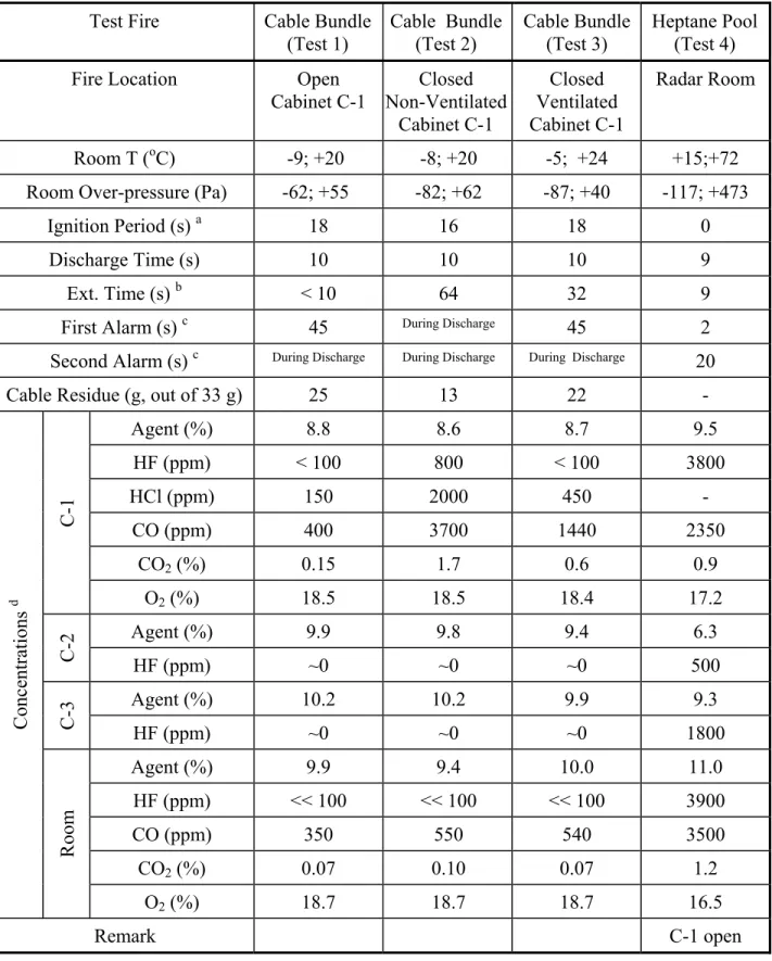
Table 2 – Fire Suppression Tests and Results
Test Fire
Cable Bundle
(Test 1)
Cable Bundle
(Test 2)
Cable Bundle
(Test 3)
Heptane Pool
(Test 4)
Fire Location
Open
Cabinet C-1
Closed
Non-Ventilated
Cabinet C-1
Closed
Ventilated
Cabinet C-1
Radar Room
Room T (
oC)
-9; +20
-8; +20
-5; +24
+15;+72
Room Over-pressure (Pa)
-62; +55
-82; +62
-87; +40
-117; +473
Ignition Period (s)
a18 16 18 0
Discharge Time (s)
10
10
10
9
Ext. Time (s)
b<
10
64
32 9
First Alarm (s)
c45
During Discharge45 2
Second Alarm (s)
c During Discharge During Discharge During Discharge20
Cable Residue (g, out of 33 g)
25
13
22
-
Agent (%)
8.8
8.6
8.7
9.5
HF (ppm)
< 100
800
< 100
3800
HCl (ppm)
150
2000
450
-
CO (ppm)
400
3700
1440
2350
CO
2(%)
0.15
1.7
0.6
0.9
C-1
O
2(%)
18.5
18.5
18.4
17.2
Agent (%)
9.9
9.8
9.4
6.3
C-2
HF (ppm)
~0
~0
~0
500
Agent (%)
10.2
10.2
9.9
9.3
C-3
HF (ppm)
~0
~0
~0
1800
Agent (%)
9.9
9.4
10.0
11.0
HF (ppm)
<< 100
<< 100
<< 100
3900
CO (ppm)
350
550
540
3500
CO
2(%)
0.07
0.10
0.07
1.2
Concentrations
dRoom
O
2(%)
18.7
18.7
18.7
16.5
Remark
C-1
open
atime from ignition start to fully burning b
c
time from ignition start to alarm sounding d
maximum for the agent, HF, HCl, CO and CO2 concentrations; minimum for the O2 concentration (C-2 was non-ventilated; C-3 had ventilation openings; cabinet doors closed unless otherwise specified.)