Design, Analysis and Optimization of the Power Conversion System for the Modular Pebble Bed Reactor System
By Chunyun Wang
B.S.M.E. Tsinghua University, 1991 M.S.N.E. Tsinghua University, 1994
Submitted to the Department of Nuclear Engineering In partial fulfillment of the requirements for the degree of
Doctor of Philosophy in Nuclear Engineering at the
Massachusetts Institute of Technology August 31, 2003
@ 2003 Massachusetts Institute of Technology All rights reserved
Signature of Author
Department of Nuclear Engineering August 31, 2003 Certified by
Ronald G. Ballinger Professor of Nuclear Engineering and Materials Science and Engineering Thesis Supervisor Certified by
Michael J. Driscoll Professor Emeritus of Nuclear Engineering Thesis Reader Certified by
Jeffrey A. Coderre Chairman, Department Committee on Graduate Students
Design, Analysis, and Optimization of the Power Conversion System for the Modular Pebble Bed Reactor System
By Chunyun Wang
Submitted to the Department of Nuclear Engineering On August 31, 2003, in partial fulfillment of the requirement of
Doctor of Philosophy in Nuclear Engineering ABSTRACT
The Modular Pebble Bed Reactor system (MPBR) requires a gas turbine cycle (Brayton cycle) as the power conversion system for it to achieve economic competitiveness as a GenIV nuclear system. The availability of controllable helium turbomachinery and compact heat exchangers are thus the critical enabling technology for the gas turbine cycle. The development of an initial reference design for an indirect helium cycle has been accomplished with the overriding constraint that this design could be built with existing technology and complies with all current codes and standards. Using the initial reference design, limiting features were identified. Finally, an optimized reference design was developed by identifying key advances in the technology that could reasonably be expected to be achieved with limited R&D. This final reference design is an indirect, intercooled and recuperated cycle consisting of a three-shaft arrangement for the turbomachinery system. A critical part of the design process involved the interaction between individual component design and overall plant performance. The helium cycle overall efficiency is significantly influenced by performance of individual components. Changes in the design of one component, a turbine for example, often required changes in other components. To allow for the optimization of the overall design with these interdependencies, a detailed steady state and transient control model was developed. The use of the steady state and transient models as a part of an iterative design process represents the key contribution of this work. A dynamic model, MPBRSim, has been developed. The model integrates the reactor core and the power conversion system simultaneously. Physical parameters such as the heat exchangers’ weights and practical performance maps such as the turbine characteristics and compressor characteristics are incorporated into the model. The individual component models as well as the fully integrated model of the power conversion system have been verified with an industry-standard general thermal-fluid code Flownet.
With respect to the dynamic model, bypass valve control and inventory control have been used as the primary control methods for the power conversion system. By performing simulation using the dynamic model with the designed control scheme, the combination of bypass and inventory control was optimized to assure system stability within design temperature and pressure limits. Bypass control allows for rapid control system response
while inventory control allows for ultimate steady state operation at part power very near the optimum operating point for the system. Load transients simulations show that the indirect, three-shaft arrangement gas turbine power conversion system is stable and controllable. For the indirect cycle the intermediate heat exchanger (IHX) is the interface between the reactor and the turbomachinery systems. As a part of the design effort the IHX was identified as the key component in the system. Two technologies, printed circuit and compact plate-fin, were investigated that have the promise of meeting the design requirements for the system. The reference design incorporates the possibility of using either technology although the compact plate-fin design was chosen for subsequent analysis. The thermal design and parametric analysis with an IHX and recuperator using the plate-fin configuration have been performed. As a three-shaft arrangement, the turbo-shaft sets consist of a pair of turbine/compressor sets (high pressure and low pressure turbines with same-shaft compressor) and a power turbine coupled with a synchronous generator. The turbines and compressors are all axial type and the shaft configuration is horizontal. The core outlet/inlet temperatures are 900/520°C, and the optimum pressure ratio in the power conversion cycle is 2.9. The design achieves a plant net efficiency of approximately 48%. Thesis Supervisor: Ronald G. Ballinger
Acknowledgements
I would like to express my deep appreciation to Professor Ronald G. Ballinger for his guidance and helpful suggestions throughout the course of my Ph.D. research.
I would like to thank Professor John E. Meyer for his suggestions for the heat balance of the cycle and Professor Hee Cheon No of KAIST, Korea for his help for developing the dynamic model. And I also would like to thank the thesis reader Professor Michael J. Driscoll.
I would like to thank Professor Neil E. Todreas and Professor Andy C. Kadak for his helpful guidance in the research progress. I would like to thank the group members, Mr. Martin Koronowski of Concepts-NREC, Mr. Peter W. Stahle and Mr. Eli Demetri of Concepts-NREC. I have really learned a lot from them.
I also would like to thank Professor Pieter G. Rousseau of Potchefstroom University for his considerable help in using Flownet, Dr. James D. Paduano, Dr. David W. Vos and Mr. Harold Brown for their valuable suggestions about the dynamic modeling of the gas turbine cycle.
I would like to deeply cherish the memory of my father, Xinhang Wang, and give the regret that, as a son, I was not in his bedside when he passed away in January 1999. Financial supports from Department of Energy, under NERI Project DE-FG03-00SF22171, and the projects of Professor Mujid S. Kazimi are gratefully acknowledged.
Table of Contents Abstract………..3 Acknowledgements………5 Table of Contents………...7 List of Figures……….…...9 List of Tables……….…..16 1. Introduction………17 1.1 Motivation………..17 1.2 Thesis contribution………
…
19 1.3 Organization of thesis………20 References………212. Background: HTGR gas turbine power plant……….22
2.1 Introduction………22
2.2 High temperature gas cooled reactor……….22
2.2.1 Reactor system………
.
.222.2.2 Reactor control………..25
2.3 Power conversion system………
...
.272.3.1 Gas turbine power conversion system………
..
272.3.2 Helium gas turbomachines………..28
2.3.3 Compact heat exchanger………...33
2.3.4 Control methods for gas turbine power conversion system………..35
2.4 Advanced gas cooled reactor design requirements………….………
…
...392.5 Overall development path…….………..40
References………41
3. Results: Gas turbine power conversion system design considerations…………...……...43
3.1 Introduction………43
3.2 General design consideration……….43
3.3 Design constraints………..48
3.4 Configuration consideration………..50
3.5 Compact heat exchanger and helium gas turbomachine design considerations..……..53
3.6 Schematic of current design………..62
3.7 Summary………63
References………65
4. Results: Model development………...66
4.1 Introduction………66
4.2 Steady state model development………...67
4.2.1 Component losses……….…………67
4.2.2 Steady state cycle calculation procedure………..76
4.2.3 Estimation of cooling mass flowrate for RPV and IHX vessel………80
4.3.1 Solution approach……….…………86
4.3.2 Sub-models of components………...88
4.3.2.1 Reactor model.……….…….88
4.3.2.2 Heat exchanger model………108
4.3.2.3 Turbomachinery model………...115
4.3.2.4 Shaft and generator model………..122
4.3.2.5 Valve model……….……...123
4.3.2.6 Pipe model……….……….123
4.3.2.7 PI controller……….……...124
4.3.3 Integration of component sub-models……….125
4.4 Summary……….…….………125
References……….…….………127
5. Results: Control system design………...….………129
5.1 Introduction……….…….………129
5.2 Control strategy……….…….……….130
5.3 Control methods……….…….………….132
5.4 Configuration of control system.……….135
5.5 Automatic control system………136
5.6 Summary……….…….………137
References……….…….………140
6. Results: Plant analysis……….……….141
6.1 Introduction……….…….………141
6.2 Steady state parametric analysis………..141
6.3 Transient analysis……….…….………..153
6.3.1 Verification with Flownet model………153
6.3.2 10% load step change – bypass valve control used………159
6.3.3 10%/min and 5%/min load ramp………168
6.3.4 Grid separation……….…….…….179
6.4 Conclusion……….…….……….182
6.4.1 Cycle design results……….…….…182
6.4.2 Control system results……….…….187
6.5 Summary……….…….………187
References………..187
7. Results: Summary and discussion……….………...…….…...188
7.1 Summary of conclusions……….…….…188
7.2 Discussion and recommendation……….190
Appendix A Concepts-NREC heat exchanger design………..192
Appendix B Concepts-NREC turbomachinery design……….204
Appendix C Intermediate heat exchanger assembly design……….……221
Appendix D Thermodynamic and transport properties of helium..………..227
List of Figures
Figure 2.1 Hexagonal fuel element for prismatic core 24
Figure 2.2 Pebble fuel element 24
Figure 2.3 Control rod arrangement in the HTR-10 26
Figure 2.4 Oberhausen plant circuit, control and cycle parameters 30
Figure 2.5 Oberhausen 2 helium turbine 31
Figure 2.6 HHV test circuit and parameters 32
Figure 2.7 Bypass control of a closed Brayton cycle 36
Figure 2.8 Closed cycle with inventory control 37
Figure 2.9 T-s diagram for part power and full power for the inventory controlled closed Brayton cycle
38
Figure 2.10 Performance of inventory, bypass and temperature control 38
Figure 3.1 Decision tree for specification of power conversion unit 44
Figure 3.2 Single-shaft arrangement 52
Figure 3.3 Three-shaft arrangement 52
Figure 3.4 Printed circuit plate 55
Figure 3.5 Stacking of printed circuit plates 55
Figure 3.6 Detail of bonded printed circuit plates 56
Figure 3.7 Examples of PCHX core 56
Figure 3.8 Unit-cell of plate fin heat exchanger 57
Figure 3.9 Stacking of plate fin heat exchanger unit-cells 57
Figure 3.10 Current schematic of the MPBR 64
Figure 4.1 Stagnation and static states in compression process 69
List of Figures
Figure 4.3 Flowchart of the steady state calculation 79
Figure 4.4 Reactor pressure vessel cooling 80
Figure 4.5 Cooling helium mass flowrate as a function of its inlet temperature at the condition that the core barrel and RPV temperatures are 390°C and 280°C, respectively
83
Figure 4.6 Core barrel temperature effects on the cooling helium mass flowrate and the heat transferred from core barrel to RPV for the condition of fixing the RPV temperature at 280°C, and cooling helium temperature at 135°C
83
Figure 4.7 IHX vessel insulation 85
Figure 4.8 Calculation diagram for a closed cycle 86
Figure 4.9 Interaction between the sub-models of the reactor model 89
Figure 4.10 Core nodal scheme 91
Figure 4.11 Nodes for core heat transport in cylindrical coordinates 92
Figure 4.12 Schematic of helium and fuel heat transfer in a node 94
Figure 4.13 Xe135 fission product chain 103
Figure 4.14 The simplified decay scheme of Xe135 103
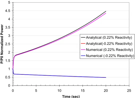
Figure 4.15 Numerical results versus analytical results for one effective group point kinetics equation
107
Figure 4.16 Xe135 buildup following core shutdown 107
Figure 4.17 Nodal scheme of a heat exchanger 109
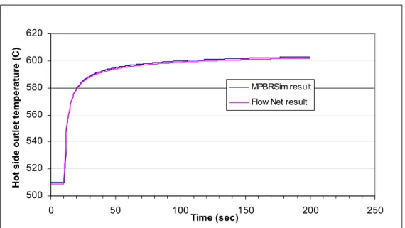
Figure 4.18 HX model verification: Hot side outlet temperature response to
cold side inlet temperature 100°C step increase at 10 sec 114 Figure 4.19 HX model verification: Cold side outlet temperature response to
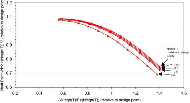
cold side inlet temperature 100°C step increase at 10 sec 114 Figure 4.20 Estimated actual and ideal enthalpy rise coefficient versus flow
coefficient of a four-stage axial turbine
List of Figures
Figure 4.21 Estimated actual enthalpy rise coefficient versus corrected flow coefficient of a five-stage centrifugal compressor
119 Figure 4.22 Estimated ideal enthalpy rise coefficient versus corrected flow
coefficient of a five-stage centrifugal compressor
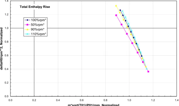
120 Figure 4.23 Estimated ideal enthalpy rise coefficient versus flow coefficient
of an 8+1 axial centrifugal compressor
120 Figure 4.24 Estimated actual enthalpy rise coefficient versus flow coefficient
of an 8+1 axi-centrifugal compressor
120
Figure 4.25 The sketch of a pipe 124
Figure 4.26 Flowchart of the dynamic model 126
Figure 5.1 Control configuration for the MPBR 130
Figure 5.2 Control feedback loops 138
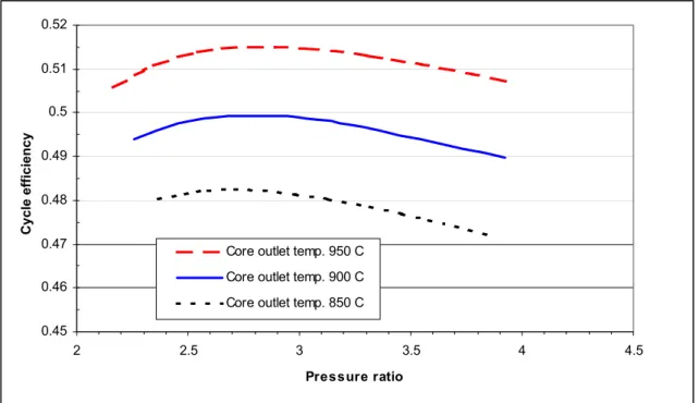
Figure 6.1 Cycle efficiency versus the pressure ratio as a function of core outlet temperature
143 Figure 6.2 The effect of compressor inlet temperature on the cycle
performance
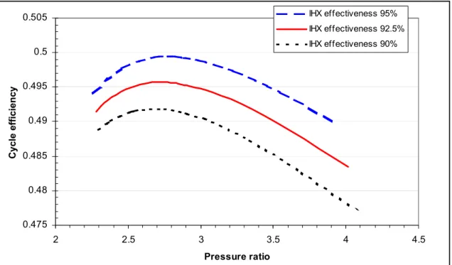
144 Figure 6.3 Effect of IHX effectiveness on the overall cycle efficiency 147 Figure 6.4 Effect of recuperator effectiveness on the overall cycle
efficiency
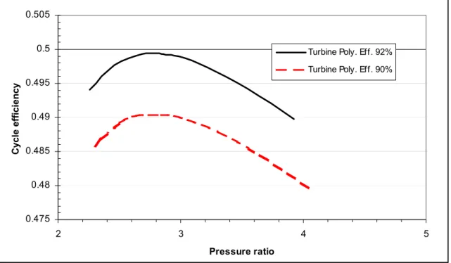
147 Figure 6.5 Effect of turbine efficiency on the overall cycle efficiency 148 Figure 6.6 Effect of compressor efficiency on the overall cycle efficiency 148
Figure 6.7 Intercooling stage number effect on the cycle efficiency 150
Figure 6.8 Cycle efficiency for three recuperator pressure loss designs
conditions 150
Figure 6.9 The effect on the cycle performance by bleeding helium from the HP compressor and MP compressor #1 to cool the turbine discs and blade roots
List of Figures
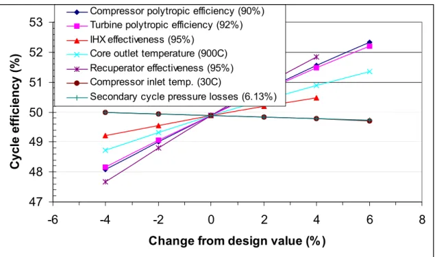
Figure 6.10 Sensitivity of cycle efficiency to component parameters 152
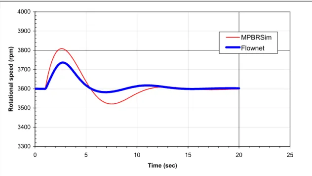
Figure 6.11 Schematic of the Flownet model 155
Figure 6.12 Power turbine shaft speed response to 20% load step reduction,
compared to the Flownet model 156
Figure 6.13 HP turbine shaft speed response to 20% load step reduction, compared to the Flownet model
156 Figure 6.14 LP turbine shaft speed response to 20% load step reduction,
compared to the Flownet model
157 Figure 6.15 Pressures response to 20% load step reduction, compared to the
Flownet model
157 Figure 6.16 Mass flowrates response to 20% load step reduction, compared
to the Flownet model
158 Figure 6.17 Compressor temperatures response to 20% load step reduction,
compared to the Flownet model
158 Figure 6.18 IHX temperatures response to 20% load step reduction,
compared to the Flownet model
158 Figure 6.19 Electric load and reactor fission power in 10% load step
reduction with bypass valve control used
161 Figure 6.20 Reactor reactivity in 10% load step reduction with bypass valve
control used
161 Figure 6.21 Power of components on the HP turbine shaft in 10% load step
reduction with bypass valve control used 162
Figure 6.22 Power of components on the LP turbine shaft in 10% load step
reduction with bypass valve control used 162
Figure 6.23 Power turbine shaft speed in 10% load step reduction with
bypass valve control used 163
Figure 6.24 Speeds of the HP turbine shaft and the LP turbine shaft in 10% load step reduction with bypass valve control used
List of Figures
Figure 6.25 Bypass valve mass flowrate in 10% load step reduction with bypass valve control used
164 Figure 6.26 Mass flowrates of the HP turbine and LP compressor in 10%
load step reduction with bypass valve control used
164 Figure 6.27 Core inlet and outlet temperatures in 10% load step reduction
with bypass valve control used
165 Figure 6.28 Fuel average temperature in 10% load step reduction with
bypass valve control used
165 Figure 6.29 Temperatures of turbines in 10% load step reduction with bypass
valve control used
166 Figure 6.30 Temperatures of compressors in 10% load step reduction with
bypass valve control used
166 Figure 6.31 Pressures of compressors in 10% load step reduction with
bypass valve control used 167
Figure 6.32 Pressures of turbines in 10% load step reduction with bypass
valve control used 167
Figure 6.33 Electric load and reactor fission power in the load ramp from 100% to 50% at 10%/min and then back up to 100% at 5%/min, bypass valve control used (Centrifugal compressor)
169
Figure 6.34 Core outlet/inlet temperature in the load ramp from 100% to 50% at 10%/min and then back up to 100% at 5%/min, bypass valve control used (Centrifugal compressor)
169
Figure 6.35 Reactivity in the load ramp from 100% to 50% at 10%/min and then back up to 100% at 5%/min, bypass valve control is used and centrifugal compressor map is used
170
Figure 6.36 Turbine-generator shaft speed in the load ramp from 100% to 50% at 10%/min and then back up to 100% at 5%/min, bypass valve control is used and centrifugal compressor map is used
170
Figure 6.37 HP turbine shaft speed and LP turbine shaft speed in the load ramp from 100% to 50% at 10%/min and then back up to 100% at 5%/min, bypass valve control is used and centrifugal
compressor map is used
List of Figures
Figure 6.38 Bypass valve mass flowrate in the load ramp from 100% to 50% at 10%/min and then back up to 100% at 5%/min, bypass valve control is used and centrifugal compressor map is used
171
Figure 6.39 Compressor pressures in the load ramp from 100% to 50% at 10%/min and then back up to 100% at 5%/min, bypass valve control is used and centrifugal compressor map is used
172
Figure 6.40 Electric load and reactor fission power in a load ramp from 100% to 50% at a rate of 10%/min, both bypass control and inventory control are used
174
Figure 6.41 Turbine-generator shaft speed in a load ramp from 100% to 50% at a rate of 10%/min, both bypass control and inventory control are used
174
Figure 6.42 HP turbine shaft speed and LP turbine shaft speed in a load ramp from 100% to 50% at a rate of 10%/min, both bypass control and inventory control are used
175
Figure 6.43 Bypass valve and inventory valve mass flowrate in a load ramp from 100% to 50% at a rate of 10%/min, both bypass control and inventory control are used
175
Figure 6.44 Power turbine and LP compressor mass flowrate in a load ramp from 100% to 50% at a rate of 10%/min, both bypass control and inventory control are used
176
Figure 6.45 Primary system mass flowrate in a load ramp from 100% to 50% at a rate of 10%/min, both bypass control and inventory control are used
176
Figure 6.46 Helium inventory in PCU in a load ramp from 100% to 50% at a rate of 10%/min, both bypass control and inventory control are used
177
Figure 6.47 Core outlet/inlet temperature and fuel average temperature in a load ramp from 100% to 50% at a rate of 10%/min, both bypass control and inventory control are used
177
Figure 6.48 Pressures of compressors in a load ramp from 100% to 50% at a rate of 10%/min, both bypass control and inventory control are used
List of Figures
Figure 6.49 Turbine temperatures in a load ramp from 100% to 50% at a rate of 10%/min, both bypass control and inventory control are used
178 Figure 6.50 Compressor temperatures in a load ramp from 100% to 50% at a
rate of 10%/min, both bypass control and inventory control are used
179
Figure 6.51 Total load and reactor fission power in simulating grid separation, bypass valve is used and centrifugal compressor maps are used
180
Figure 6.52 Bypass valve mass flowrate in simulating grid separation,
bypass valve is used and centrifugal compressor maps are used 181 Figure 6.53 Turbine-generator shaft speed in simulating grid separation,
bypass valve is used and centrifugal compressor maps are used 181 Figure 6.54 HP turbine shaft speed and LP turbine shaft speed in simulating
grid separation, bypass valve is used and centrifugal compressor maps are used
182
Figure 6.55 Cycle parameters using printed circuit heat exchanger as IHX 186
List of Tables
Table 2.1 Operating conditions for compact heat exchangers 34
Table 2.2 Potentially applicable HX technology for HTGR 35
Table 3.1 Summarization of the pro’s and con’s for indirect cycle 46
Table 3.2 Properties of helium and air at 1000 K and 3 MPa 47
Table 3.3 Pipe inner diameter required for different pressures at fixed mass flowrate 126.7 kg/s, fixed temperature 30°C and fixed flow velocity 120m/s
48
Table 3.4 IHX design conditions 59
Table 3.5 Recuperator design conditions 59
Table 3.6 IHX parametric design calculation results for PFHX configuration
60 Table 3.7 Recuperator parametric design calculation results for PFHX
configuration 60
Table 3.8 Design details of recuperator with effectiveness of 95%,
pressure loss of 0.8% (hot side), 0.334% (cold side) 61
Table 4.1 MPBR reactor core pressure loss calculation 73
Table 4.2 Reactor core neutronic data 100
Table 4.3 Normalized fission power distribution in pebble bed region 100
Table 4.4 Fission production fractions and decay constants 102
Table 4.5 IHX design details (Printed Circuit configuration) 113
Table 4.6 Compressor parameter definitions 117
Table 4.7 Turbine parameter definitions 118
Table 5.1 Parameters of PI controllers 139
Table 6.1 The component parameters for parametric analysis 142
1. Introduction
1.1 Motivation
A key challenge in the production of electricity is reducing the CO2 emissions to the
environment. Meanwhile, the world energy consumption is increasing as a necessity of the industrialization process of the developing countries. This will require economic alternatives for electricity generation rather than using oil and natural gas. Nuclear energy is a non CO2
emission energy source. Though, currently, a large amount of electricity in the world is provided by nuclear power, there are some problems with public acceptance due to safety concerns and economics. The next generation of nuclear power plants, which possess demonstrable safety and economically competitiveness, are now being developed. The modular high temperature gas cooled reactor system is inherently safe and has the potential to compete with natural gas in the electricity market. The 5th largest utility in the world located in South Africa, ESKOM, is now developing a commercial unit using a pebble bed reactor with a power of 268MWth to generate electricity [1]. MIT is also exploring the development an advanced modular pebble bed reactor system (MPBR) for the production of electricity with high efficiency and low cost.
The design of the power conversion system significantly affects the plant efficiency and the capital cost. In the Rankine cycle, using steam as working fluid, the temperature is limited by the high pressure imposed by the pressure-temperature relationship along the saturation line. Thus the maximum efficiencies of the water cooled reactor systems are no more than 35%. With current technology, a gas temperature as high as 950°C in the gas cooled reactor system is possible. The Brayton cycle, implemented in a gas turbine cycle, has the potential of increased efficiency, less risk of water ingress accident and a decrease in system complexity and O&M costs. It thus becomes an attractive choice for the power conversion system for the pebble bed reactor system. There are two types of cycles – direct and indirect, each has own advantages and disadvantages. Recuperaton and intercooling have been proposed to improve the thermodynamic efficiency. In consideration of gas properties, helium is the most suitable gas as the working fluid in the Brayton cycle at these temperatures. In this case, the development of the helium gas turbomachinery is vital to the
implementation of the gas turbine cycle. For the indirect cycle, the intermediate heat exchanger (IHX) is crucial. A large shell-and-tube heat exchanger will make the system uneconomical[2]. The same is also applied to the recuperator; a bulky and costly one will defeat the economic and compact advantage of the system. For a modular nuclear system, the components must be shipped by truck or rail. Therefore, it is essential to design a compact power conversion system that complies with the existing codes and can be fabricated with current technology or a near-term extension of the technology.
As an advanced reactor system, it must be capable of meeting utility requirements for load following and control band. Since the power conversion system differs greatly from a conventional steam cycle, the question of operating stability also arises naturally. Thus, an effective control system needs to be designed. The dynamic characteristics of the
components of the plant and the performance of the coupled gas turbine and compressors are important for the control system design. In practice, the transient performance and control system design are inseparable. In previous analyses, the reactor core and the power
conversion system are often treated separately, and then integrated as each other’s boundary condition. For example, in the analysis of the power conversion system, it is usual to assume a constant reactor core outlet temperature due to its large thermal inertia. This assumption is valid only during a relative short time period after a transient. It is essential that a dynamic model which integrates simultaneously the reactor core and the power conversion system be developed. With the dynamic model, we can investigate the interaction between the design and dynamic performance. Examples are the design of turbomachinery and the position of the bypass valve. The control scheme and the control configuration can be explored using a dynamic model through simulation of load ramps. Also the consequences of accidents such as grid separation can be found.
The main objective of this thesis is to provide the preliminary design for an
economically competitive power conversion system, giving the control system design and simulating the load transients. The power conversion system must satisfy all codes and standards and does not require significant R&D effort. Key questions, such as IHX design, gas turbine and compressor matching as well as operating stability, need to be answered. This clearly suggests the need for developing an approach to optimize the plant system parameters and to simulate the plant.
1.2 Thesis contribution
The establishment of an overall technical basis for the MPBR will require a sufficiently developed design to allow all of the key questions regarding technical feasibility and economic viability to be answered. Since the individual component performance will
interact strongly with steady state and transient performance of the plant, it will be important that system dynamic behavior be adequately understood. In this thesis, the followings have been accomplished with emphasis on the power conversion system.
(1) With the power conversion system, the design constraints are derived. A schematic of the power conversion system coupled with the pebble bed reactor is designed. The performance and costs of the components are determined.
(2) A steady state heat balance model has been developed, programming with Visual Basic. The model is flexible enough to allow the exploration of plant design options. For example, the user can choose different intercooling stage numbers. The model takes as user input, the efficiency and pressure losses for each component, then it gives the cycle overall pressure ratio, the net output electricity, and thus the net plant efficiency.
(3) Parametric calculations are conducted with the steady state model. The salient parameters of the plant are determined based on the requirement that the components could be fabricated with no significant R&D effort and at reasonable capital cost. (4) The specifications of the heat exchangers and turbomachinery are provided.
Parametric calculations for a Plate Fin Heat Exchanger are conducted. (5) A first principle dynamic model is developed based on the actual physical
parameters of the plant, such as the overall characteristics of the turbomachinery. The model is coded using a simulation language ACSL[3]. It integrates the reactor core and the power conversion system simultaneously. A specific control technique is incorporated in the dynamic model for assessing the control scheme.
(6) A control system is designed. In the power conversion system, bypass valve control and inventory control are utilized. The control scheme is proposed. The control system of the plant provides the automatic control functions for power regulation in
accordance with the grid load requirement and safety protection to the plant for the anticipated accidents.
(7) Load transients are simulated. And the power ramping and step change capability are studied.
1.3 Organization of thesis
This thesis is organized into seven chapters. Chapter 2 reviews the existing technologies related to the gas cooled reactor system, especially the pebble bed reactor system and the gas turbine power conversion system. The development history of the high temperature gas cooled reactor system is described. Also, the pebble bed reactor designed by ESKOM will be introduced. With the gas turbine cycle, the operating experience of the helium
turbomachinery in Oberhausen, Germany which represents the only real experience with the turbomachinery to this point is reviewed. The requirement of an advanced gas cooled reactor design and the development path in this report are presented.
Chapter 3 presents the developed gas turbine power conversion system design criteria and the current design. The advantages and disadvantages of the direct versus indirect cycle, closed versus open cycle and cycle variations are discussed. The three-shaft arrangement and the single-shaft arrangement for the turbomachinery configuration are compared. The design constraints for coupling with the pebble bed reactor are derived. The fabrication feasibility for IHX, recuperator and some design considerations are discussed. Parametric calculations for the Plate Fin heat exchanger are presented. The current schematic of the MPBR is presented.
Chapter 4 presents the steady state model and the dynamic model. For the steady state model, the losses caused by components are discussed in detail and the calculation
procedure is presented. The cycle efficiency losses caused by vessel cooling are analyzed. For the dynamic model, the numerical solution approach that gives convergent results is presented and the models for each component are discussed in detail. The reactor model consists of three components: (1) the point kinetics, (2) the two-dimensional thermal
is introduced to characterize the multi-stage turbomachines. The PI controller algorithm is incorporated in the model. Some verifications are presented for each component model. Chapter 5 presents the control system design. The control strategy for meeting utility requirements is designed. In terms of the reactor control and the power conversion system control, the potential control methods are discussed. The control configuration for the MPBR is given.
Chapter 6 presents the steady state parametric calculations and dynamic simulations for load ramps. Verifications with another code Flownet [4] for simulating a load ramp are given. The simulation of the load ramps is intended to demonstrate the prominent operating characteristics of the plant design. The aim of this chapter is to give the salient parameters of the MPBR and the control features.
Chapter 7 presents the final conclusions and discussions.
At the end of the thesis, five appendices are added that give the IHX and recuperator design information and the turbomachinery design results carried out by Concepts-NREC, the IHX assembly designed by MIT, helium properties and nomenclature.
References:
[1] ESKOM document, No. 001929-207/5, “PBMR safety analysis report, chapter 5, reactor nuclear design”, Revision B.
[2] Y. Muto, K. Hada, H. Koikegami and H. Kisamori, “Design of intermediate heat exchanger for the HTGR-closed cycle gas turbine power generation system”, JAERI-Tech 96-042, October, 1996.
[3] AEgis Simulation, Inc., “Advanced continuous simulation language reference manual”, September, 1999.
2. Background: HTGR gas turbine power plant
2.1 Introduction
In this chapter, the world-wide development of the high temperature gas cooled reactor system is described briefly. Two core types, prismatic and pebble bed, are introduced. The control methods applying to the reactor and the power conversion system are explained. After some discussion of the gas turbine cycle, the technologies and experiences of heat exchanger and helium gas turbomachinery are described. Finally, the requirement of the advanced gas cooled reactor system as a candidate “Generation IV” reactor system and the development path in this study are presented.
2.2 High temperature gas cooled reactor
2.2.1 Reactor system
The first commercial gas-cooled power reactor started operating at Calder Hall in England in 1956 and produced 40 MW of electricity. These first power reactors were graphite
moderated with natural uranium metal fuel rods and cooled by circulating 0.8MPa CO2 at an
outlet temperature of 335°C. These “Magnox” reactors, had a low power density – 0.1 to 0.5 MW(e)/m3, using natural uranium as fuel and graphite as the moderator. To improve the thermodynamic efficiency and fuel utilization of the Magnox reactors, the Advanced Gas-Cooled Reactors (AGRs) were developed. In AGRs, 2.5% enrichment UO2 pellets were used
as fuel. That led to outlet temperature increases to 560°C from the 350 to 400 °C of the Magnox reactors. 26 Magnox reactors and 14 AGRs have been constructed in the United Kingdom and 8 Magnox reactors in France[1, 2]. With the experience of Magnox and AGR reactors, CO2 corrosion of the steel components and carbon corrosion by CO2 remain as
areas of concern[1].
In parallel with the development of AGR, in the mid-50s the idea for a high temperature gas cooled reactor (HTGR) was proposed. HTGRs utilize ceramic coated particle fuel, in
graphite matrix. Helium is used as the coolant and graphite as the moderator. The combination of graphite core structure, ceramic fuel and inert helium permits very high operating temperature.
There are two core types for the HTGR – prismatic and pebble bed. For the prismatic core, the coated particles are loaded in cylindrical fuel compacts that are inserted in hexagonal graphite fuel elements, as shown in Figure 2.1[3]. The elements contain other holes for control rod insertion, flow of gas coolant and holding the burnable poison rods. The fuel elements are packed in the core and replaced as a batch when they are depleted. The prismatic type HTGRs have been constructed in United Kingdom, United States and more recently in Japan. The Dragon reactor in the United Kingdom was the first HTGR prototype, which operated first in July 1965 and was decommissioned in March 1976 after long full power operation [4]. The Peach Bottom Unit 1 was the first HTGR prototype in the United States. It achieved initial criticality in March 1966 and full power in May 1967. The plant went into commercial operation in June 1967 and was shut down for decommissioning in October 1974 [4]. This was followed by a large commercial prismatic plant, Fort St. Vrain in the United States. Fort St. Vrain was a steam cycle plant with a capacity of 842 MW(t) and 330 MW(e). Initial electric power generation was achieved at Fort St. Vrain in December 1976. It was shut down permanently in 1990 due to its low availability primarily caused by problems with the water-lubricated bearing of the helium circulator [2,5].
Recently, the Japanese test reactor HTTR reached first criticality in 1998 and reached full power in 2001. It is a 30 MW(t) prismatic core HTGR design with outlet temperature 850°C[6].
For the pebble bed core, the coated particles are embedded in spherical graphite fuel “pebbles” with a diameter of approximately 60 mm, as shown in Figure 2.2[7]. One typical pebble contains ten to twenty thousand coated particles. The pebbles randomly packed in the core cavity forms the fuel system. Fresh pebbles are added to the top of the core and the burned pebbles are extracted at the bottom. After measuring the burnup, the partially burned pebbles are recycled to the top of the core for another cycle. The coolant flows through the interstices presented in the bed. The control rods are inserted either directly into the core, or into the side reflector, depending the core size. Pebble bed reactors have been developed in Germany: the AVR test reactor and the THTR power plant. AVR reached criticality in
Figure 2.1 Hexagonal fuel element for prismatic core [3]
August 1966 and operated until December 1988 [8]. The THTR nuclear power plant included a steam cycle to generate a net output of 296 MW electricity. The construction of THTR-300 began in 1971 and was completed in 1984. The plant was connected to the electrical grid of the utility in November 1985. It was shutdown permanently in 1989[8]. A pebble bed test reactor HTR-10 has been built in China [9, 10]. It achieved its first criticality in December 2000 and was connected to the electrical grid of the utility in January 2003. Excellent safety characteristics can be achieved for HTGRs due to their typical features: the high heat capacity of the graphite core, the chemical stability and inertness of the
coolant, the high retention capability of fission products in the fuel particles and the inherent negative temperature coefficient of reactivity of the core. With a deliberate decrease in the power level and reconfiguring of the reactor, the modular type HTGR concept was proposed in the early 1980s. The modular type HTGR provides the extra unique characteristic that the fuel temperature will not exceed the failure temperature following postulated accidents just by using passive heat transfer mechanisms. Currently, a joint United States – Russian Federation program is developing the GT-MHR project for burning weapon-grade plutonium [11, 12]. GT-MHR is a modular, prismatic reactor design with
600MWt/286MWe. Another commercial modular HTGR is being developing by ESKOM in South Africa – PBMR [7,13]. PBMR is a modular pebble bed reactor design with 265 MWt/116.3 MWe. Both GT-MHR and PBMR include a direct closed gas turbine cycle, which will be described in detail in the section 2.3. In this study, MPBR will use a pebble bed reactor core with thermal power of 250 MW similar to the PBMR core.
2.2.2 Reactor control
In the pebble bed reactor core, there are usually two reactivity control systems – the control rod system and the small absorber ball system, as shown in Figure 2.3 [14,15,16]. The control rod system consists of several control rods and the same number of drive
mechanisms. It is usually utilized as the power regulating and control system and the first shutdown system as well. The control rod drive mechanism inserts the control rod into the side reflector and removes it out. For a large pebble bed reactor, the control rods might be
Figure 2.3 Control rod arrangement in the HTR-10 [14]
inserted into the reactor core. However, the disadvantages are that the rod insertion will interfere with the pebble fuel elements and may damage them. The small absorber ball system is the second shutdown system. If emergency shutdown is required and the control rod system cannot be assured to work, boronated (boron carbide) balls are dropped by gravity into side channels to shut down the system. In order to restart the system, the small absorber ball system provides means to remove the absorber balls from the channels and to put them back into the ball storage vessels.
In the indirect cycle design, the circulator provides the pressure head for the helium to overcome the pressure losses through primary system. The mass flowrate in the primary system is proportional to the circulator speed. If the circulator speed is adjusted, the mass flowrate is changed correspondingly. Therefore, the mass flowrate in the primary system can
be manipulated by adjusting the circulator speed. In AVR and THTR, mass flow control in the primary system was achieved by varying the circulator speed [1].
2.3 Power conversion system
2.3.1 Gas turbine power conversion system
The advantages of coupling an HTGR with a closed Brayton cycle as the power conversion unit (PCU) have been recognized for many years. However, the actual system can not be realized until key technologies have been developed. The key technologies include:
(a) The size of gas turbines must be increased to accommodate the heat energy transformation proposed for a HTGR module;
(b) The technology for an effective compact heat exchanger is available. The volume and capital cost must be reasonable;
(c) The feasibility of a large magnetic bearing is possible with current technology. Using magnetic bearings instead of lubricated bearings obviates the oil-ingress problem which contaminates the helium coolant.
The gas turbine HTGR plant holds the promise for electricity generation with high efficiency. The value can be 43% to 48%[12,13]. Rankine cycle nuclear plants, such as PWR and BWR, usually provide an efficiency around 33% for electricity generation. Both the conceptual designs of the GT-MHR and PBMR adopt a direct closed gas turbine cycle for the power conversion system. The PCU of the GT-MHR utilizes a single-shaft arrangement consisting of a turbine, an electric generator, and two gas compressors on a common, vertically oriented shaft supported by magnetic bearings. The PCU also includes a recuperator, precooler and intercooler[3,11]. In the PCU of the PBMR, there are three vertically oriented shafts. The high-pressure turbine drives the high-pressure compressor while the low-pressure turbine drives the low-pressure compressor. The power turbine drives the electric generator. Also, a recuperator, precooler and intercooler are used in the PBMR[7,13].
However, implementing the gas turbine nuclear plant depends on the technical feasibility of helium gas turbomachines and the compact heat exchanger. The following describes the technologies for helium gas turbomachines and compact heat exchanger.
2.3.2 Helium gas turbomachines
Gas turbines have been used throughout the world for marine/aviation propulsion and power generation in land based power plants for many years. Large scale gas turbine output power can be over 200MW for a land based power plant [17]. However, its working fluid is combustion gases (from the mixture of air and fuel, such as natural gas or oil). Experience with design and operation of closed cycle helium turbomachinery has been finite but limited. Two large-scale helium facilities for testing closed cycle helium turbomachinery have been operated in Germany: (1) the 50MW(e) Oberhausen 2 helium turbine plant (EVO), and (2) the high temperature helium test plant (HHV).
1. 50 MW(e) Oberhausen 2 helium turbine plant (EVO)[18]
The design of the EVO test plant was for an electrical power of 50 MW and heating (district heat) power 53.5 MW. The thermal heat source for the closed helium cycle is a fossil-fired heater. The basic flow scheme and design parameters are shown in Figure 2.4. A two-shaft arrangement was selected for the turbomachinery. The high-pressure (HP) turbine drives the low-pressure (LP) compressor and HP compressor on the first shaft with a rotational speed of 5,500rpm and the LP turbine drives the generator synchronizing with the grid (rotational speed 3,000rpm) on a separated shaft. Both shafts are interconnected by a gear. Since the power generated from the HP turbine is consumed by the compressors, there is not much power to transfer from the HP turbine to the generator through the gear. As shown in Figure 2.4, the HP turbine inlet temperature and pressure are 750 °C and 2.7 MPa, respectively. Helium mass flowrate for the cycle is 84.8kg/s.
The power regulation of the EVO test plant uses the same principle adopted for closed cycle air turbine plants. Both inventory control and bypass valve control, which will be described in the next section, are used.
The HP turbine has 7 stages with 50% reaction. The turbine rotor disc and the blade feet are cooled by extracting a helium stream from the HP compressor outlet. The LP turbine has 11 stages. One picture of the turbine is shown in Figure 2.5. The HP compressor and LP compressor have 15 stages and 10 stages, respectively, both with 100% reaction. Oil lubricated-labyrinth seals are used for sealing. The housing and nozzles are also cooled. The plant was connected to the grid on November, 1975. Up to the end of 1988, the helium turbine plant had been operated approximately 24,000 hours. A total of 11,500 hours operation had been at the design temperature of 750°C. During operation many components and systems showed good performance. As the “first-of-a-kind” of a large helium turbine plant, some problems, such as vibration and low power output, arose unexpectedly for some components. The maximum electricity power output was 30.5MW, which is much less than the design nominal data of 50MWe.
Inlet temperature (°C) Inlet pressure (MPa) 1. LP compressor 25 1.05 2. Intercooler 83 1.55 3. HP compressor 25 1.54 4. Recuperator, HP side 125 2.87 5. Heater 417 2.82 6. HP turbine 750 2.7 7. LP turbine 580 1.65
8.1 Precooler (heating part) 460 1.08
8.2. Precooler (cooling part) 169 1.06
9. Gear
10. Regulation bypass valve 11. Storage reservoirs 12. Transfer reservoirs
Figure 2.5 Oberhausen 2 helium turbine
2. High temperature helium test facility (HHV) [18]
The HHV facility was built at KFA, Juelich, Germany for testing of large scale helium turbomachinery. The flow schematic and other circuit parameters are shown in Figure 2.6. Helium gas with a flow rate of approximately 200 kg/s is circulated the system by means of electrically-driven turbomachinery. The compressor power is 90 MW, of which one part is provided by the turbine generation power of about 46 MW and the difference is supplied by a 45 MW electric motor. As result of the compressor work, the helium is heated up to 850°C (1000 °C for short time periods) so that a fossil-fired heater is not needed. The system pressure is 5.0MPa.
A two-stage turbine and an eight-stage compressor are on a shaft with a synchronous rotational speed of 3000rpm. The blade feet, rotor and housing are cooled by means of a cooling gas system or a sealing gas system. For the cooling gas system, radial-type
compressors circulate the cooling helium of 56.8 kg/s at an inlet temperature of 236°C and inlet pressure of 4.9MPa and an outlet pressure of 5.35MPa at 258°C. The radial-type compressors are driven by a 6.5MW electric motor.
During the initial operation, oil ingress and excessive helium leakage occurred. After having overcome the initial problems, the HHV facility was successfully operated for about 1100 hours, of which it operated for about 325 hours at 850°C. The measured results show that the compressor and turbine have a higher efficiency than the design value.
M Test Section 2 3 4 5 1
Legend: 1. Test section; 2. Helium turbine
3. Duct to compressor inlet 4. Compressor 5. Electric motor
Temperature (°C) Pressure (MPa) Flow rate (kg/s)
Compressor outlet 850 5.12 212.0
Test section inlet 850 5.12 201.0
Turbine inlet 826 4.97 209.0
Main cooler inlet 390 4.95 53.5
Cooling gas compressor inlet 236 4.90 56.8
Cooling gas for coaxial hot gas duct
300 5.12 22.9
Sealing gas outlet 50 52.75 2.3
2.3.3 Compact heat exchanger
The heat exchangers incorporated in the power conversion system of HTGR, the recuperator and/or the IHX, need to have a high effectiveness, and high mechanical characteristics as they operate under conditions of high pressure and high temperature. Furthermore, they are required to be as compact as possible to limit their size to enhance the plant layout.
Many ways are used to classify heat exchangers. For example, the fluid types (gas-gas, gas-liquid, liquid-liquid), the flow arrangement (counter-flow, cross-flow), surface
compactness, the construction type and industry are used.
In a heat exchanger, the heat-exchanger surface (or matrix) is the structure in which heat transfer takes place from one fluid to another fluid. One of the fundamental characteristics of a heat-exchanger surface is the surface area per unit of volume occupied by the surface. A “compact heat-exchanger surface” is defined as a surface configuration or matrix having a “large” surface area per unit of volume. Usually, any matrix with an area density greater than 328 m2/m3 is defined as compact matrix or compact surface [20]. A compact heat exchanger is constructed from compact surfaces.
As discussed in reference [21], a shell-and-tube type heat exchanger is too large to be economic without an extensive materials qualification for HTGR application. Therefore, in this work, the non-tubular compact heat exchanger will be considered as the base design for the recuperator and IHX. Many current technologies of compact heat exchangers are
available including plate fin, spiral, microchannels, and plate.
Plate fin heat exchangers (PFHE) have been extensively used in applications such as industrial, natural gas liquefaction, air separation and hydrocarbon separation. The fins are brazed to the parting sheets and then the parting sheets are assembled to form a single block. The blocks are stacked and then the inlet and outlet headers are welded to the blocks to construct a heat exchanger. Numerous fin configurations such as straight fin, straight perforated fin and serrated fin have been developed.
Spiral heat exchangers (SHE) are often used in applications where a phase change occurs. In the SHE, the fundamental part is two metal plates welded together and rolled to form the flow passages.
Microchannel heat exchangers are heat exchangers in which the flow channels are around or less than 1 mm in diameter. The small channels are manufactured on flat plates by means of technologies such as chemical etching, micromachining or electron discharge machining. A typical microchannel heat exchanger is the printed circuit heat exchanger developed by the Heatric company[22]. In the printed circuit heat exchanger, the plates are stacked and then diffusion bonded. Compared to other type heat exchangers, the
microchannel heat exchanger is heavier if the sizes are the same.
Plate heat exchangers (PHE) have been widely used in the applications of chemical, petrochemical, district heating and power industries. A PHE is constructed by the stacking of corrugated plates. Different materials such as aluminum or stainless steel are used for different operating conditions and three technologies such as gaskets, welding and brazing can be used to ensure tightness. The applicable limits for different types of compact heat exchangers are shown in Table 2.1[23]. Note that the maximum pressure and maximum temperature cannot be reached simultaneously.
Under HTGR conditions, a high pressure difference is imposed on the recuperator (>4MPa) and high temperature operation (no lower than 850°C) is required for the IHX. Thus, only welded, brazed or diffusion bonded heat exchangers could be used, as shown in Table 2.2 [23].
Table 2.1 Operating conditions for compact heat exchangers [23]
Technology Max. pressure
(MPa)
Max. temperature (°C)
Fouling
Stainless steel plate fin heat exchanger 8 650 No
Aluminum plate fin heat exchanger 8-12 70-200 No
Ceramic plate fin heat exchanger 0.4 1300 No
Spiral heat exchanger 3 400 Yes
Diffusion bonded heat exchanger 50 800-1000 No
Brazed plate heat exchanger 3 200 No
Welded plate heat exchanger 3-4 300-400 Yes/no
Table 2.2 Potentially applicable HX technology for HTGR[23]
Technology Pressure Effectiveness Reliability
Spiral 3 MPa Good Good
Plate-fin 8 MPa Very good Good
Welded plates 3-4MPa Good Good
Diffusion bonded 50MPa Good Very good
2.3.4 Control methods for gas turbine power conversion system
The closed cycle provides unique opportunities for power regulation. The closed cycle, helium turbine plant can be designed using the same principles used for closed air turbine plants. Figure 2.7 is a schematic of a regenerated Brayton cycle. The commercial power plant offers the advantage of enabling the power generation to match the required load. Several control methods -- bypass valve control, temperature modulation and inventory control, might be of interest for use in the nuclear gas turbine power conversion system.
1. Bypass valve control
As shown in Figure 2.7, a bypass valve bleeds high-pressure gas to short-circuit the heat source and the turbine. This throttling process is a source of irreversibility and thus reduces the cycle part load efficiency. One part of the high-pressure gas, bypassing the turbine, results in turbine output decrease. At the same time, the cycle pressure ratio is reduced, and thus the mass flowrate through the compressor increases. If the rotational speed remains constant, the velocity triangles for the compressor and turbine are both not in the optimum condition, resulting in a decrease of the cycle efficiency.
The advantage of bypass valve control is that it can alter the turbine output rapidly to match the load variation. Thus, to achieve fast load change, bypass valve control is usually used in the closed gas turbine system, especially in a large system since the inventory control response is relatively slow. In the event of grid separation, the bypass valve control is always used to prevent the shaft from overspeeding.
Precooler Turb. Comp. Generator Recuperator Heat Source Bypass valve
Figure 2.7 Bypass control of a closed Brayton cycle
2. Temperature modulation
Decreasing the turbine inlet temperature results in a decrease of the turbine output power and the turbine efficiency, and thus the cycle efficiency. The temperature modulation scheme utilizes this principle.
For the HTGR gas turbine plant, adjusting the reactor power can alter the core outlet temperature, and thus the gas turbine inlet temperature. Due to the large thermal inertia of the reactor core, the change of the core outlet temperature is relatively slow. Accordingly, temperature modulation is not suitable for fast power control.
3. Inventory control
As shown in Figure 2.8, the inventory of the working fluid in the closed power system is controlled by connecting it to a storage vessel. A compressor may be used to pump the working fluid from the system to the storage vessel as the load decreases. The reduced mass inventory in the system results in a smaller mass flow rate, and thus a lower turbine power
output. When the load increases, the working fluid in the storage vessel is fed back to the system. To minimize the heat energy moving from the system to the storage vessel, the working fluid can be removed from a point with the lowest temperature of the cycle. With the reduced mass flowrate, the temperatures and pressure ratio of the cycle remain constant, thus the thermodynamic cycle is unaltered.
When the temperatures remain constant, the sonic speed of the working gas does not change as the mass flowrate decreases. The blading and flow passage geometries fix the Mach number. This implies the flow velocities along the cycle are constant and thus the mass flowrate is proportional to the flow density. Also, the mass flowrate is proportional to the pressure level. The T-s diagrams for part and full power are shown in Figure 2.9[23]. As the pressure level decreases, the pressure losses will be slightly changed because the decrease in density also causes a decrease in the Reynolds number. The effect is that the cycle pressure ratio shifts from the design value and thus the cycle efficiency decreases slightly. Precooler Turb. Comp. Generator Recuperator Heat Source Storage vessel
Figure 2.10 shows the cycle efficiency under different control methods. We can see that the cycle efficiency at partial load remains high by using inventory control while the bypass valve control and temperature modulation degrade the cycle performance.
High power cycle Low power cycle T
s
Figure 2.9 T-s diagram for part power and full power for the inventory controlled closed Brayton cycle [24]
2.4 Advanced gas cooled reactor design requirements
The HTGR gas turbine plant is being developed as a generation IV nuclear energy system which offers advantages in the areas of economic competitiveness, safety and reliability. The MPBR promises a number of significant advantages over conventional commercial water-cooled technology. First, by fully using the high gas temperature, the MPBR provides a thermal efficiency approaching 45%. Higher efficiency leads to improved economics. The MPBR will be a demonstrably safe nuclear plant system. This implies that the system will be designed such that any postulate accidents will not result in fuel melt. Thus, no fuel damage and release of radioactivity to the environment will occur. This inherent safety is due to the fact that the core will be designed with a negative temperature coefficient of reactivity and the decay heat can be removed to the ground by a passive heat transfer mechanism. The passive heat transfer mechanism includes conduction and natural
convection. Since the coolant is inert helium in the MPBR, corrosion of the components is not a concern so that the cost for replacement of the degraded components caused by corrosion such as in water-cooled reactors is avoided. This simplifies operation and maintenance and thus improves the economics.
Overall, the objective of the MPBR is that its economics can compete with natural gas. With regard to the balance of plant design, the requirements can be summarized as follows:
(a) High efficiency over a broad operating range; (b) Load following;
(c) Low capital cost; (d) Constructability; (e) Modularity; (f) Transportability; (g) Code compliance.
These goals will require that the design provides high efficiency during full power operation and also high efficiency during partial power operation. From a control point of view, the plant must be capable of meeting the utility requirement for load following as an advanced nuclear system. Considering the components in the power conversion system, the constructability, complying with current codes and with no significant R&D effort need to
be considered in making design decisions. Modularity is a key consideration for component design so that the failed module can be unplugged and replaced quickly by a spare one. The component modules are manufactured off-site and transported to the construction site by flat bed truck or rail car.
2.5 Overall development path
The overall development path followed in this work was to first build a “reference” design which satisfies all the codes and standards. Based on the “reference” design, a steady state model was developed and the key limitations were identified. The steady state model was used to calculate the plant thermal efficiency, the pressure ratio of the power conversion system, and other parameters such as temperatures and pressures in the cycle. Then some key questions were identified. The questions include those related to the feasibility of the IHX and recuperator, the helium gas turbine and compressor, system control and the
consequence of indirect cycle choice. To design the control system for the power conversion system, a dynamic model was then developed. The dynamic model integrates the reactor core and the power conversion system and incorporates the control schemes. Then a path was quantified to remove limitations of the “reference” design. Meanwhile, the steady state model and the dynamic model were used to optimize the design. To satisfy all the
requirements and limitations, design iterations and compromises were sometimes required. Finally, an advanced design was developed.
References:
[1] Gilbert Melese, Robert Katz, “ Thermal and flow design of helium-cooled reactors”, American Nuclear Society, 1984.
[2] H. L. Brey, “Developmental history of the gas turbine modular high temperature reactor”, IAEA TCM on gas turbine power conversion system for modular HTGRs, Nov. 14-16, 2000, Palo Alto, California.
[3]http://www.ga.com/gtmhr/gtmhr1.html.
[4] R. A. Moore, et al., “HTGR experience, programs, and future applications”, Nuclear engineering and design 72(1982), pp. 153-174.
[5] H. L. Brey, “Fort St. Vrain circulator operating experience”, IAEA Specialists' meeting on gas-cooled reactor coolant circulator and blower technology. San Diego, CA (USA), 30 Nov. - 2 Dec. 1987.
[6] http://www.jaeri.go.jp/english/temp/temp.html. [7] http://www.pbmr.co.za/.
[8] International Atomic Energy Agency, “Gas cooled reactor design and safety”, Technical report series No. 312, Vienna, 1990.
[9] Y. Xu, “Chinese point and status”, Proceedings of the conference on high temperature reactors, Petten, Netherlands, April 22-24, 2002.
[10] Yuanhui Xu, Kaifen Zuo, “Overview of the 10 MW high temperature reactor – test module project”, Nuclear engineering and design 218(2002),13-23.
[11] M. P. LaBar, “The Gas Turbine – Modular Helium Reactor: A promising option for near term deployment”, General Atomics report No. GA-A23952.
[12] A. Kiryushin, N. G. Kodochigov, “ GT-MHR project”, Proceedings of the conference on high temperature reactors, Petten, Netherlands, April 22-24, 2002.
[13] K. N. Kumar, A. Tourlidakis, P.Pilidis, “Performance review: PBMR closed cycle gas turbine power plant”, IAEA TCM gas turbine power conversion systems for modular HTGRs”, November 14-16, 2000 in Palo Alto, California.
[14] Y. Q. Wu, X. Z. Diao, etc, “Design and tests for the HTR-10 control rod system”, Nuclear engineering and design 218 (2002) 147-154.
[15] H. Z. Zhou, Z. Y. Huang, X. Z. Diao, “Design and verification test of the small
absorber ball system of the HTR-10”, Nuclear engineering and design 218 (2002) 155-162. [16] Xinglong Yan, “Dynamic analysis and control system design for an advanced nuclear gas turbine power plant”, MIT PhD thesis, 1990.
[17] Tony Giampaolo, “The gas turbine handbook: principles and practices”, Fairmont press, 1997.
[18] I. A. Weisbrodt, “Summary report on technical experiences from high-temperature helium turbomachinery testing in germany”, International Atomic Energy Agency, Vienna, Nov. 1994.
[19] K. Bammert, “Operation and control of the 50-MW closed-cycle helium turbine Oberhausen”, ASME paper 74-GT-13.
[20] Northern Research and Engineering Corporation, “The design and performance analysis of compact heat exchangers”, 1965.
[21] Y. Muto, K. Hada, H. Koikegami and H. Kisamor, “Design of intermediate heat exchanger for the HTGR-closed cycle gas turbine power generation system”, JAERI-Tech, 96-042, October, 1996.
[22] http://www.heatric.com.
[23] B. Thonon, E. Breuil, “Compact heat exchangers technologies for the HTRs recuperator application”, IAEA TCM gas turbine power conversion systems for modular HTGRs”, November 14-16, 2000 in Palo Alto, California.
[24] Reiner Decher, “Energy conversion systems, flow physics and engineering”, Oxford university press, 1994.
3. Results: Gas turbine power conversion system design
considerations
3.1 Introduction
High core outlet temperature is the main advantage of the high temperature gas cooled reactor. To take full advantage of the high outlet temperature, a new power conversion system, differing from the Rankine cycle, must be used.
The general design considerations, such as working fluid and cycle options, and the
design constraints will be addressed. The advantages and disadvantages for cycle variations will be demonstrated. The feasibility of the compact heat exchangers and helium gas turbomachinery will also be investigated.
3.2 General design considerations
Figure 3.1 is a decision tree which depicts the decision making path to narrow the choice of system cycle and the numerical analysis. It provides an outline of the issues which need to be addressed. The trade-offs are considered based on the technical characteristics and economics.
One of the main advantages for the high temperature gas cooled reactor is that it can provide a high core outlet temperature (> 850°C). When steam is used in a Rankine cycle, its temperature is limited by the high pressure imposed by the pressure-temperature relationship along the saturation line. One can overheat the steam but complicate the plant layout. A practical temperature limit is around 300-400°C for the Rankine cycle. To take advantage of the high core outlet temperature of the HTGR, a Brayton cycle is preferred.
Other design considerations involve four aspects: closed cycle versus open cycle, direct cycle versus indirect cycle, working fluid choice and system pressure. The following sections describe them.
The combustion gas turbine cycle usually adopts an open cycle, in which the system inlet pressure is atmospheric and air is the working fluid. When utilizing nuclear energy as the heat source, radioactivity is one of the main considerations in power conversion system design. In this case, the direct and open cycle is inadvisable. By using an intermediate heat exchanger (IHX) to separate the nuclear system (primary system) and the “secondary” system, one obtains the so called indirect cycle; however, using an open cycle in the secondary system makes the inlet pressure in the power conversion system equal to atmospheric pressure, about 0.1MPa. This pressure level would lead to an IHX having a large volume. An approximate estimation shows that the volume of the IHX in an open air
Nuclear energy
(a)Heat source
Direct cycle
Open cycle
Brayton cycle
Rankine cycle
Closed cycle
Indirect cycle
Helium
N
2, CO
2, …
Multi-shaft
Single-shaft
Recuperated,
Intercooled
Non
(b) Thermodynamic cycle (c) Coupling with environment(d) Coupling with reactor (e) Working fluid choice (f) Arrangement of power conversion unit
(e) Cycle variations
cycle is a factor of 15 larger than that in a helium closed cycle and a factor of 3 larger than that in an air closed cycle[1]. Therefore, in terms of compactness and capital cost, a closed cycle is favored.
Direct cycle vs. indirect cycle
There are two types of closed cycles – direct cycle and indirect cycle. The direct cycle circulates working fluid exiting from the reactor core directly to the power conversion unit and the working fluid exhausting from there back to the core, while the indirect cycle utilizes an IHX to separate the primary system and the power conversion unit. The IHX transfers the thermal energy from the primary system to the working fluid of the gas turbomachines, which convert the thermal energy to mechanical energy. The mechanical energy is then transformed into electrical energy by the generator. The direct cycle has the advantages of higher efficiency (higher turbine inlet temperature) and less components (without the IHX). Its disadvantage is that the power conversion unit is contaminated, which results in higher cost for maintenance and higher component costs due to their adaptation to nuclear standards. Also, there is potential damage to the primary boundary by turbomachine failures, i.e., turbine blade failure. The indirect cycle has a lower efficiency compared with the direct cycle because the IHX results in a temperature drop from the reactor outlet to the turbine inlet. The elimination of contamination in the power conversion unit in the indirect cycle makes maintenance simple and allows components to be built to non-nuclear
standards, thus cost less. Since there are two circuits in the indirect cycle, a depressurization accident occurring in one circuit imposes a high pressure differential on the IHX, and could cause IHX failure. These great care must be taken to include appropriate safety systems to prevent this from happening. Table 3.1 summarizes the pro’s and con’s for the indirect cycle. The indirect cycle is chosen for the MPBR.