DETECTION OF SUBSURFACE FRACTURES AND PERMEABLE ZONES
BY
THE ANALYSIS OF TUBE WAVES
W.B. Beydoun. C.H. Cheng and M.N. Toksoz Earth Resources Laboratory
Department ofEarth and Planetary Sciences Massachusetts Institute of Technology
Cambridge. MA 02139. U.S.A.
ABSTRACT
In Vertical Seismic Profiling tube waves are generated by compressional waves impinging on subsurface fractures or permeable zones. The amplitude of tUbe waves is dependent upon the formation permeability, the length of the fracture, and on the source frequency. The generation of tube waves is formulated theoretically and the relative effects of these parameters are studied individually. Field examples are shown for open fractures in granite. From tube wave amplitudes normalized to P-wave amplitudes, calculated permeabilities are on the order of 400 millidarcys.
INTRODUCTION
In field experiments with compressional wave Vertical Seismic Profiling (VSP) surveys, it has been observed that tube waves are generated at fractures intersecting the borehole (Huang and Hunter, 1981a,b). Examples of tube waves originating at fractures and propagating up and down the borehole are shown in a VSP section in Figure 1. A possible mechanism for the generation of tUbe waves is that the incident P-waves compress the fracture and inject a fluid pulse into the borehole. Figure 2 schematically illustrates this efficient mechanism for the generation of tube waves.
The fluid pulse mechanism for the generation of tube waves is formulated mathematically. The geometrical model is that of a fracture intersecting a borehole normal to the borehole axis. with a compressional plane wave impinging normally on the fracture. First, the volume of fluid ejected from the fracture into the borehole is calculated. Then, the tUbe wave amplitudes generated in the borehole fluid and in the formation are evaluated. The in-situ fracture permeability can then be estimated from the ratio of the tUbe wave amplitude to the P-wave amplitude measured in the formation or in the fluid using this model.
THEORY OF FRACTURE COMPRESSION AND FLUID FLOW
Consider the specific example of a parallel-walled, fluid-filled fracture with low aspect ratio (Width to length ratio «10-3). The fracture is penetrated
equilibrium with the fluid in the borehole when there is no perturbation. A wave impinges on the fracture at normal incidence. The wavelength of the P-wave is much greater than the fracture widthL(t). For very small strains, L(t) is assumed to oscillate about the static shape La as:
L(t)
=
Lo
+
<:"0 cos(c.>t)where 2<:"0 is the maximum fracture displacement (Figure 3) and <:"o«L o.
( 1)
for <:"0«La.
To simplify the calculations of the fluid injection from the fracture into the borehole, the following assumptions are taken: (1) One dimensionallarninar flow (low Reynold's number) within the fracture, (2) the fluid compressibility is small, (3) the fluid injected into the borehole does not significantly perturb the borehole pressure Po, (4) low frequency approximation with frequency dependence and (5) the fracture permeability, K, does not vary with time.
Two-dimensional Model
The two-dimensional problem, where the fracture is infinitely long in the y direction, will be solved first. The fluid flow rate in the presence of a pressure gradient ap (x ,t)/ ax is related to the fracture width L(t), the fluid viscosityj.J.,
and the fracture permeabilityK by Darcy's law:
q(x,t) = - KL(t) ap(x,t)/ax (2)
j.J.
The volume of fluid ejected from the fracture into the borehole during the one-half cycle of the incident wave (see Appendix) is:
tJ. V;w(K)
=
-(0[.JLf
F(GJ,(ol Lo)
(3)rr-yJ.l. where:
T/2
F(c.> ,<:"0/La) '" 2c.>
J
(T/2-t)li sin(c.>t) dt aThe effective length of the fracture, d, is defined as the radial distance from the borehole wall to a point at which the pressure gradient (see Appendix, equation A.4) falls to lie times the pressure gradient at the borehol.e wall over a time interval of T/2. The effective fracture length is given by the expression:
d(K)
=
[2:/]*
(4)
EXtension to Three Dimensions
The volume obtained in (3) is two dimensional. The actual borehole geometry involves a three-dimensional configuration which can be approximated by extrapolation of the two-dimensional solution assuming the geometry is axisymmetric. This geometrical extrapolation is assumed to be independent of the small fluid compressibility and of the low frequency of
10-2
(
(
(
excitation.
The two-dimensional stationary problem consists of an incompressible viscous fluid flow, in the ~ direction ( oriented away from the borehole), enciosed between two parallei planes separated by a distance L. The boundary
conditions for pressure are: at ~=R, P =Po and at ~=R+d, P =PI (PI> Po). The pressure distribution is:
(PI - Po)
P2D = (~-R) d
+
Po (5)(6) The 3D axisy=etric problem involves two discs separated by a distance L with radial fluid flow into the center. The outer radius is r =R+d and inner
radius is r=R. The boundary conditions are: at r=R, p=Po and at
r =R+d, P=PI " The stationary solution for the pressure distribution is:
PSD = (PI -Po) In(r/R) +Po In( (R;d))
The rate of fluid flow for these two problems is
KL dP2D q2D= -f.J. d~ . or explicitly (7a) (7b) (8a) (8b)
Use of Navier-Stokes equation and the continuity equation (Landau and Lifchitz, 1971) with the assumptions stated in this paper indicate that the permeability of two-disc radial fluid flow is the same as the permeability of two parallel planes fluid flow. Combining the two results of (8) leads to
qSD
=
211'R Xq2D (9)where
X(K) =
_---:~d_:_:_::_=_
The Xcomponent is defined as the geometrical factor; d is the effective length defined previously in (4) and R is the borehole radius. For any given time interval the equation relating the two- and three-dimensional volumes is similar to equation (9).
(10) where b. V is the volume ejected from the circular fracture into the borehole during a time interval of T/2.
TUBE WAVE GENERATION
Tube waves are low frequency Stoneley waves (White, 1965; Cheng and Toksoz, 1981). These gUided waves reach their largest amplitudes at the solid-fiuid· boundary and decay approximately exponentially away from it. The fiuid pulse b. V forced from the fracture into the borehole by an incident compressional wave generates tube waves which propagate up and down the borehole.
To determine the relationship between the ejected fiuid volume and the tube waves generated, the tube wave volumetric strain in the fiuid (eii) and
seismic potentials are used. Let us define z = 0 as the plane of symmetry of the fracture. Further, the tube wave and the P-wave are assumed to have the same frequency. The integrated tube wave volumetric strain in the borehole fiuid (at z =0) in the time period T/2 can be equated to the fiuid volume ejected from the fracture, b. V(K), over the same time period. In axisymmetric cylindrical coordinates b. V(K) can be expressed as
T/2 R
~V(K)
=
21TC J Jeii(r,t,z=O)rdr dt (11)o
0The volumetric strain and amplitude of the tube wave can be determined using the seismic potential for the tube wave (Cheng and Toksoz, 1981). The tube wave pressure amplitude in the borehole fiuid p T and its displacement
amplitude in the formation
u[
are described by:pT=p/0)2Clo(7tr) r:5.R- (12) ( ( (
u[
=
A [kKo(lr)+
mGKo(mr)] where G=__
2:;l;,::~:....2~K:..ll.:.:(l.:..r:..,)--: k (c2_2~2) K1(mr) A=
.,:C_7t..:....:1..:.,l(:.:,7t;.:.r..:..)..,:(;.:.2:;;.{32_-...:c_2:..,) l c2K1(lr)The factor C is calculated from equation (11), and is given by
10-4
(13)
(14)
(15)
C(K)
=
(16)(17) The amplitudes of the up and down going tube waves will be the same because of symmetry.
The fracture permeability can be evaluated by considering the inverse problem. The in situ fracture permeability can be determined from the tube
wave amplitude normalized to the direct P-wave amplitude in the ftuid (pressure ratio) or in the formation (displacement ratio). The' ratio of fracture displacement to incident P-wave displacement, <:01
u:,
is a function of the fracture shape (aspect ratio), the stiffness of the formation, and the fluid compressibility. For a thin fracture with iarge surface area and small fluid compressibility, <:0'"u:,
and when there is no ftuid in the fracture,<:o '" 2u:
(ex: a free surface). In the following caiculations <:0 will be assumed to be equal to uzo.,At low frequencies (>"»R) ,the P-wave pressure in the borehole ftuid can be written in terms of displacement in the formation (White, 1965):
a l·al_Pl02a,(1-2(32/a,2)
p I Uz - (32(1 _ 02;a(2)
where
I
u
z aI
='"
Uza.Using <:0
=
u za and equations (12) to (17), the ratios of fracture induced tube wave amplitudes to incident P-wave amplitudes can be determined. The pressure ratio in the borehole (measured by a hydrophone) is:Q(32
(1 -
c2/ a2)Io(nR)
pT/pa
=
C(K)
(18){'oc2a (1 - 2(32/a2)
The vertical component of displacement ratio at the wall of the borehole (measured by an anchored borehole geophone) is:
u!'luza= [kKo(lR) +mGKo(mRl] AI <:0 (19) The factor A is related to C(K) by equation (15) and C(K) is related to the volume of ftuid ejected in T12 by equation (16). The fluid volume is related
to the fracture permeability by combining equations (10) and (3). Equation (18) or (19) can be solved to determine the fracture permeability K. Normally, given the formation and ftuid properties, displacement or pressure ratios can be determined as a function of frequency with permeability, K, as a parameter. These values can then be compared with observations to determine K.
A simple relation exists between the fracture permeability (K) and the fracture hydraulic conductivity (or coefficient of permeability) (K;,):
K;,
=
K PI g I j.1. , (20)where g is the gravitational acceleration. The Sl units of K are m2, and the
the common unit is 10-3 a'T7Ll sea, which is sometimes called the darcy: to avoid
any confusion this nomenclature shall not be used. In these units the following relation exists: ld '" 10-3 em/sec.
RESULTS AND DISCUSSION
In order to demonstrate the different efficiencies of tube wave generation. we considered three separate formations: a granite, representing a typical crystalline rock; a "hard" sediment that would represent relatively dense carbonate and hard sandstones; and a "sediment" to represent the more typical sedimentary rocks such as sandstones and shales. The properties of these formations and other physical parameters used in this study are listed in Table 1. The tube wave phase velocity a is calculated by solving the period equation (Cheng and Toksoz. 1981) for the given formation and borehole parameters as a function of frequency.
Pressure and Displacement Amplitude Ratios
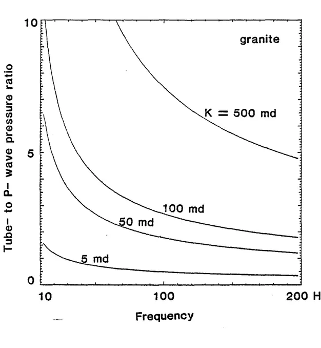
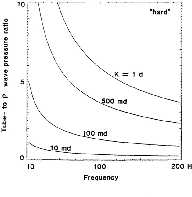
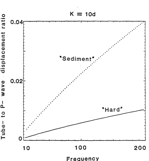
The ratios of tube waVe amplitudes to P- wave amplitudes are shown in Figures 4, 5 and 6. The first comparison made is that of the ratios of pressure amplitudes inside the borehole fluid. This is useful for interpreting the hydrophone data. The second comparison is that of the ratios of displacements that may be measured by a borehole seismometer locked to the borehole wall, Only the vertical (z) component of the displacement is considered. The tube wave particle motion at the borehole interface is highly elliptical and it is important to specify the component of displacement under consideration. Figure 4 shows the frequency dependence of the tube wave amplitUde for the two formations considered. Owing to the much larger amplitudes of tube waves in the fluid it is preferable to use hydrophone data as opposed to geophone data to detect highly permeable zones. The borehole essentially acts as an amplifier. The tube wave pressure amplitudes in the fluid decrease with increasing frequency. The displacement ratios in the formation increase with frequency. The pressure ratios for granite. "hard" and "sediment" models are shown in Figures 5a, band c. for different values of permeability. Higher fracture permeability yields higher tube wave amplitudes. For a given fracture permeability the "hard" formation gives a higher value of the tube wave pressure amplitude in the fluid, and a lower value of the tube wave displacement amplitude in the formation than the "sediment" (Figure 6).
Non-horizontal Fractures
For the two-dimensional case in which the fracture does not perpendicularly intersect the borehole, the normal displacement of the fracture wall,
<:1'
can be expressed in terms of the inclination,", of the fracture with respect to a plane normal to the borehole. The fluid volume ejected is found by replacing<:0
by<:,
=
<:0
cos("), where<:0
=
u."'.
Equation (16) becomes:C
=
f
(K) cos(") (21)where
10-6
The factor C is proportional to the tube wave amplitudes (equations 12 and 13). Therefore C is determined directly from the data.
f
(K) is a monotonically increasing function of the permeability K. The fracture inclination, 1>, in our problem is assumed to be zero; therefore K is calculated by the following equation:C
=
f(K) (22)Given the tube wave amplitude (I.e., C), this model (1)=0) will yield a lower bound
of the in situ fracture permeability of a tilted fracture (equation (21),1>"0). Field Example
Field examples of tube wave generation in a borehole that intersects open fractures in granite are shown in Figures 1 and 7 (Huang and Hunter, 1981b). These examples are pressure measurements in the borehole fluid. Comparison of data from the televiewer, core logs and the tube waves show a good correlation between tube wave generation and open fractures. For open fractures at several depths, the tube wave to P- wave amplitude ratios were measured. These are listed in Table 2. The borehole radius is about 3.8 cm. The generated tube wave amplitude is dependent on the borehole radius (roughly inversely proportional to the borehole cross-sectional area). A granite model is calculated with a borehole radius of 3.8 cm. The pressure ratios as a function of permeability and frequency are shown in Figure 8. The mean frequency of tube waves (and P- waves) is about 200 Hz. Using the observed amplitude ratios the permeability for each fracture zone was determined using Figure 8. They are listed in Table 2. and range from 18 to 67 millidarcys. These values are consistent with other permeability calculations in fractured granite as compiled by Brace (1980).
Conclusions
Tube waves can be used to detect open fractures intersecting a borehole and to determine an equlvalent fracture permeability using tube wave to P-wave amplitude ratios in the borehole fluid (pressure ratio). It should be noted that the tube- to P- wave pressure ratio in the borehole fluid is approximately 3 orders of magnitude greater than the displacement ratio in the formation. For this reason it is preferable to use hydrophone data, as compared to wall-locked borehole geophone data, to locate these permeable zones. It is important to mention that a number of assumptions were made in this study and complex "eqUivalency" was established when going from the 2-dimensional cartesian geometry to a circular crack model. Additional theoretical work is now in progress to solve the 3-dimensional problem directly.
Table 1.Physical parameters used in this study Formation o.(m; s) ~(m;s) p(kg;m S) granite 5500 3300 2700 "hard" 4500 2500 2300 "sediment" 3000 1200 2100 fln; '" ,,,nn n 1?nn
fluid viscositv
"
=
10 S Poiseuillesfluid incomnressibilitv ",-I
=
2. 109 Paborehole radius R
=
0.1 mTable 2.
Calculated fracture permeablity for a granite model from observed
p T;Pa and for a frequency of 200 Hz . . Den th7m\ 80 130 392 460 ",T;",a 4.5 3 2 3.5 K(md) 67 35 18 45 NOMENCLATURE ( ( ( c d f f;(z), K;(z) K
Xc
k L(t) La l m n p(x,t) p~ ptube wave phase velocity effective length of fracture P-wave or tube wave frequency
modified Bessel function of the i-th order fracture permeability (1 darcy
=
10-12 m2 )fracture hydraulic conductivity (10-s em; sec) OJ;e. tube wave vertical wavenumber
fracture width
static fracture width
k(1-e2; 0(2)*, tube wave radial wavenumber from P-wave contribution
k(l-cS; (IS)*. tube wave radial wavenumber from S-wave contribution
k(l-cS;
0.])*.
tube wave radial wavenumber from fluid P-wave contributionfluid pressure distribution in the fracture static borehole pressure at a given depth
generated tube wave pressure amplitude in borehole fluid in the vicinity of the fracture
10-6
(
(
q(x,t) Q(t) R uz« /;V T
a
at (3r
E:'ii ((t) (0 J.k PPt
X GJpressure amplitude in the borehole fluid of the first P-wave arrivaL in the vicinity of the fracture
rate of fluid flow in the fracture source function
borehole radius
vertical displacement amplitude in the formation
of the first P-wave arrival, in the vicinity of the fracture generated tube wave vertical displacement amplitude in the formation, in the vicinity of the fracture
two-dimensional volume of fluid ejected by the fracture in T12
three-dimensional extrapolation of /;V2D
lIf, P-wave or tube wave period
compressional (P-) wave velocity of the formation compressional (P-) wave velocity of the fluid shear (S-) wave velocity of the formation fluid compressibility
tube wave volumetric strain in the fluid normal displacement of fracture wall maximum ((t )
dynamic fluid viscosity formation density fluid density geometrical factor
2trt, P-wave or tube wave angular frequency
ACKNOWLEDGEMENTS
We thank C.F. Huang of the Geological Survey of Canada for many valuable discussions.
APPENDIX
The net change of fiuid dq in a volume element L(t)dx (Figure 3.) is due to the volume of fluid ejected by the fracture closure and the compressibility of the fluid (no mass is generated or lost in the element). During a time increment _dt, this total change is:
dq dt
=
dL(t) dzdt+
L(t)rap(x,t) dxdt (A.i)dt at
where
r
is the fluid compressibility and dL(t)1 dt=
-GJ(o sin(GJt), the velocity of the fracture wall. The net storage given by (A.i) must equal the net volume of fluid !aq (x ,t)1 axl
dxdt flOWing into the differential volume, giving.£..-
[K L(t) EP-.(x,t) ] =L(t) ap(x.t) + dL(t)ax J.k ax
r
at dtobtained:
(A.2) (
with the boundary conditions for pressure
p(x,t=O) =Pa x~O
p(x=O,t) =Pa t~O
ap(x,t)lax
=
°
x=
=This last condition states that there is no fluid flow in the fracture far (x »d)
from the borehole intersection.
Equation (A.2) is a one-dimensional inhomogeneous diffusion equation. The heat conduction analogy corresponds to a semi-infinite half-space (x;;,O)
having ",2 as thermal diffusivity and a time varying heat source Q(t). The
solution to this partial differential equation (A.2) is
p(x,t) =Pa -
j
Q(t-7) erf [
x JZ] d7o 2", 7
•
where erf (z)
= _;..
I e_,2
dt is the error function.v 11" a Note that lim P(X,t)=PO-7-1in [ L(t) ] ,,~. La
+
~a ( (c
The pressure gradient follows from (2)
ap(x,t) _
- - --=
1I'
Q(t)-7 exp - - 7(_x2 ) -1/2 d7ax "'V1l" O . 4",2 7 (A. 4)
The rate at which fluid flows is given by equation (2). By calcuiating the volume ejected from the fracture for the maximum fracture displacement 2~0,
we can obtain the maximum volume ejected in a finite amount of time. This maximum volume occurs dUring a time interval of
t
= T12. Therefore the volume of fluid forced from the fracture into the borehole in T12 is:T/2 AV2D
=
I
q(x=O,t) dt a or explicitly, where (A.5) T/2 , F(c.J,~al Lo)=
c.JI I
a 0 1 - (rol Lo)cos (c.Jt) s"'n("7), "~ d7 dt 1 - (~olLa)cos(c.J7) (t - 7)JZ 10-10Computation shows that for increasing frequency, F(c;;J;ol L o) decreases. As the frequency increases less fluid is ejected into the borehole. For ~o«Lo, an
asymptotic expression for F can be found by interchanging the order of integration in the (r,t) plane:
T/2
F(c;;,O)
=
2c;;J
(TI 2-t)* sin(c;;t) dto
REFERENCES
Brace, W.F., 1980, Permeability of crystalline and agillaceous rocks: Int. J. Rock Mech. Min. Sci. & Geomech. Abstr., v.17, p.24l-251.
Cheng, C.H. and Toksoz, M.N., 1981, Elastic wave propagation in a fluid-filled borehole and synthetic acoustic logs: Geophysics, v.46, p.1042-l053.
Huang, C.F. and Hunter, J.A., 1981a, The correlation of "tube wave" events with open fractures in fluid-filled boreholes: Current Research, Part A, Geological Survey of Canada, Paper 8l-lA, p.36l-376.
_ _ _ _ _ _ _ _ _ _, 1981b, A seismic "Tube Wave" method for in-situ estimation of fracture permeability in boreholes: S.E.G. Preprint Series, 51st Annual International Meeting, Los Angeles, v.l, E1.4 p.23-46.
Landau, L. and Lifchitz, E., 1971, Mecanique des Fluides, MIR Publications, Moscow.
White, J.E., 1965, Seismic Waves, Radiation, Transmission and Attenuation; McGraw Hill Book Company.
o
time
{seconds)
0.1
0.2
(O - l - - - ' - - - J
100
Figure 1. Example of fracture generated tube wave in a VSP (after Huang and Hunter, 1981b). 10-12 ( ( ( (
..
~-
.._<la..·=""",-p-SOU RCE----....,
,
,...':'.::",:,i,"..:.:
I'''0';' ....\ :':.... ':"".':'. ',.,.:".: ,,,.:,.':., Ul W~
;:
w
CD ;:)I-I
l Y FRACTURED ZONE\
FRACTURE PERMEABILITY DETECTION P WAVE VSPFigure 2. Schematic diagram of tube wave generated from P-waves impinging on a subsurface fracture zone.
( ( .~.. ... ": .'. .'. .
..
~ ". ';. .'.
Inddent P...:wave "':. . !.•'"....
,".::'
l
~& ..
~:.
80REHOLE ~ ~:, "./!:; ../:!.:~;.:..;., ..>,' ':" '. :.".
._ :..:': ,.
..
,:'<:,
...
FLUID
if.
..".:;-../ ,. ,'.:
.<.;',:..~. \ : , . 'FORMATION::m:-~_}=~C===:~r::-"~i~_&~
~
...
~.
__._._._---.-- 1:
WP;y;;;;;;;;;N/hW;;/)>TI."»»"...m....J:---
(Wm»~/?/.""".~::~"'~-'r::~Tm>
.. ...'"
..
1 ;"":"~::" ""r,(,;;<L~:~)
";'.' ..
,,:.~L,UIO~fILlEri;~:~Cy~!~,;';;
;----·d"'-··--'-"
Figure 3. Fracture modei used in this study.
50
20
(A) "Hard" T c( 4u /u
xlO
.
;
~
.
.' .... .'10
o
10 .' 100 K=
2 darcys200 Hz
(B)lISedimentll
30
\
pT/p<t20
/
.... T c(xl0
3
..~u/uz10
010
100
200
Hz K = 8 darcysFigure 4. Ratios of tube to P- wave pressures and displacements in two different formations as functions of frequency.
granite
( ( (200
Hz
K -
500 md
100
~md
-o
10
o
;:
a1...
Q)...
:::lrn
rn
Q)...
c.
Q)5
>
a1==
I Q.o
-
I Q) ..Q :::lI-Frequency
Figure 5a. Tube to P- wave pressure ratios as functions of frequency and permeabilityin a granite.
500 md
K
=
1 d
5
o
-
ca
...
Q)...
='
en
en
Q)...
Co Q)>
ca
3:
Ia.
o
-
I Q) .Q='
I-200 Hz
100
Frequency
r~md
o
tL---================J
10
Figure 5b. Tube to P- wave pressure ratios as functions of frequency and permeabilityin a "hard" formation.
5·
.
·sediment-0 (
.-
....
~...
Q)...
; j II) II)K
-5 d
( Q)-....
Q. Q)>
~==
I Q. 0....
I Q).c
~
; j--
I-100 md
-JO md
0
10
100
(200 Hz
Frequency
Figure 5c, Tube to P- wave pressure ratios as functions of frequency and permeabilityin a "sediment",
o
K
=
10d
-
...
~-
c
Q)E
Q)o
~ Coen
"0·Sediment·.···
Q)0.02
>
~==
" ".
, >200 Hz
100
"OL-..._ _...
~_ _-'--
--'-~~~....J10
I Q) .0 :::l I-Ia.
o
-Frequency
Figure 6. Tube to P- wave vertical displacement ratios in two different formations as a function of frequency.
o
time (seconds)
0.1
0.2
~'""
c
-..c
-
0.450
(]) V500
Figure 7. Further examples of tUbe waves generated by fractures in a VSP (after Huang and Hunter, 1981b).
30
0-
ro
...
0)...
::lrn
rn
0)...
0-0)>
15
ro
==
IC-o
-
I 0) .0 ::lI-"Granite"
=
100md
~_om_d
j
200 Hz
100
.Frequency
O,-~_-,--~~~-,-~~~-,-_~_...J10
Figure 8. Tube to P- wave pressure ratios as functions of frequency and permeability in a granite, with a borehole radius of 3.8 em.
10-22