Publisher’s version / Version de l'éditeur:
Vous avez des questions? Nous pouvons vous aider. Pour communiquer directement avec un auteur, consultez la première page de la revue dans laquelle son article a été publié afin de trouver ses coordonnées. Si vous n’arrivez pas à les repérer, communiquez avec nous à PublicationsArchive-ArchivesPublications@nrc-cnrc.gc.ca.
Questions? Contact the NRC Publications Archive team at
PublicationsArchive-ArchivesPublications@nrc-cnrc.gc.ca. If you wish to email the authors directly, please see the first page of the publication for their contact information.
https://publications-cnrc.canada.ca/fra/droits
L’accès à ce site Web et l’utilisation de son contenu sont assujettis aux conditions présentées dans le site LISEZ CES CONDITIONS ATTENTIVEMENT AVANT D’UTILISER CE SITE WEB.
Optics Express, 27, 7, pp. 9838-9847, 2019
READ THESE TERMS AND CONDITIONS CAREFULLY BEFORE USING THIS WEBSITE.
https://nrc-publications.canada.ca/eng/copyright
NRC Publications Archive Record / Notice des Archives des publications du CNRC : https://nrc-publications.canada.ca/eng/view/object/?id=1a28ff1f-4924-46e6-b055-3e49716ad0ce https://publications-cnrc.canada.ca/fra/voir/objet/?id=1a28ff1f-4924-46e6-b055-3e49716ad0ce
This publication could be one of several versions: author’s original, accepted manuscript or the publisher’s version. / La version de cette publication peut être l’une des suivantes : la version prépublication de l’auteur, la version acceptée du manuscrit ou la version de l’éditeur.
For the publisher’s version, please access the DOI link below./ Pour consulter la version de l’éditeur, utilisez le lien DOI ci-dessous.
https://doi.org/10.1364/OE.27.009838
Access and use of this website and the material on it are subject to the Terms and Conditions set forth at
Ultra-wideband Ge-rich silicon germanium mid-infrared polarization
rotator with mode hybridization flattening
Vakarin, V.; Ye, W. N.; Ramírez, J. M.; Liu, Q.; Frigerio, J.; Ballabio, A.;
Isella, G.; Vivien, L.; Alonso-Ramos, C.; Cheben, P.; Marris-Morini, D.
Ultra-wideband Ge-rich silicon germanium
mid-infrared polarization rotator with mode
hybridization flattening
V. V
AKARIN,
1,2,5,*W. N. Y
E,
1J. M. R
AMÍREZ,
2,6Q. L
IU,
2J. F
RIGERIO,
3A. B
ALLABIO,
3G. I
SELLA,
3L. V
IVIEN,
2C. A
LONSO-R
AMOS,
2P. C
HEBEN,
4AND
D. M
ARRIS-M
ORINI21
Department of Electronics, Carleton University, 1125 Colonel by Dr., Ottawa, ON K1S 5B6, Canada 2
Centre de Nanosciences et de Nanotechnologies (C2N), Université Paris Saclay, Université Paris Sud, CNRS, 91120 Palaiseau, France
3
L-NESS, Dipartimento di Fisica del Politecnico di Milano, Polo di Como, Via Anzani 42, I 22100 C, Italy
4
National Research Council of Canada, Ottawa, 1200 Montreal Road, ON K1A 0R6, Canada 5
Currently with Imec, Kapeldreef 75,3001 Leuven, Belgium 6
Currently with III-V lab, a joint lab from Nokia Bell Labs, Thales and CEA, 1 avenue Augustin Fresnel, 91767 Palaiseau Cedex, France
*vevakarin@gmail.com
Abstract: In this work we investigate the implementation of ultra-wideband polarization
rotator in the mid-infrared spectral region. A new design method of the rotation section is proposed, yielding a polarization rotator with an extinction ratio of at least 15 dB in a wavelength range of 2 µm. For a spectral range wider than 3.8 µm, an extinction ratio of at least 10 dB is achieved for this design. The device is 1660 µm long and the associated insertion loss is below 1.2 dB on the full operational wavelength range. The influence of geometrical parameters with respect to the design method to obtain such a broadband behavior is discussed. Finally, to increase the tolerance to fabrication errors, a tapered rotator design is proposed. Such a device can support up to ± 100 nm fabrication errors and still guarantees remarkable broadband behavior. To the best of our knowledge, this is the first time an integrated polarization rotator is designed to operate for the wavelength range of 4 to 9 µm with a bandwidth exceeding 2 µm.
© 2019 Optical Society of America under the terms of the OSA Open Access Publishing Agreement
1. Introduction
The mid-infrared (mid-IR) spectral region comprising the wavelength range from 2 to 20 µm is of significant interest for many applications, including medical diagnosis [1], biosensing [2], astronomy [3], security [4], etc. This is particularly because unique molecular and biological absorption features can be found in this spectral range. Commercially available mid-IR spectroscopic systems are bulky and expensive and integrated solutions are being investigated to develop miniaturized, low cost, mass produced and broadband systems. In this context, numerous platforms have been investigated: III-V materials [5,6], chalcogenide glasses [7,8] and a family of Si compatible platforms such as silicon on insulator (SOI) [9], suspended Si [10], Si on sapphire [11,12], Germanium (Ge) on Si [13–16], Silicon Germanium (SiGe) [17,18] and Ge-rich SiGe on graded buffer [19–26]. A plethora of photonic components has been implemented on these platforms: waveguides, cavities [7], Mach-Zehnder interferometers and spectrometers [21,24], (de)multiplexers [14], reconfigurable circuits [15] and modulators [27], to name a few. Moreover, the implementation of light sources has been studied and supercontinuum generation has successfully been implemented on different platforms [28,29,18]. Among Si compatible materials, SiGe and Ge-rich SiGe alloys are of particular interest because of their large
#356322 Journal © 2019
https://doi.org/10.1364/OE.27.009838 Received 27 Dec 2018; revised 13 Mar 2019; accepted 18 Mar 2019; published 25 Mar 2019
transparency window in mid-IR [19,21,24] and strong nonlinear optical effect [25]. In this work, we exploit Ge-rich SiGe alloys to build an ultra-wideband polarization rotator. While various photonic building blocks have been developed for the mid-IR, comparatively less attention has been paid to the on-chip polarization control [30–32]. For example, polarization management is important for free space communications where the polarization of the incoming signal is not known [22]. Polarization rotators based on different approaches are widely used in classical telecommunication bands [33–36]. The polarization rotator is also an important component for polarization agnostic photonic components such as arrayed waveguide gratings [37] for on-chip signal processing. Furthermore, using both orthogonal polarizations on-chip appears advantageous as photonic components can be designed with ultimate performance depending on the polarization of light, while nonlinear processes such as harmonic generation can take advantage of polarization diversity for mode phase matching. In this paper, first we introduce a new approach and corresponding design rules to obtain a wideband polarization rotator. The performance of the device is first estimated with an analytical approach based on modal analysis and then optimized with 3D eigen mode expansion (EME) propagation simulations performed with a commercial solver [38]. Finally, a tapered geometry is introduced, yielding an ultra-wideband operation and a large fabrication tolerance of ± 100 nm.
2. Broadband rotator waveguide
The mid-IR polarization rotator is designed for the Ge-rich SiGe platform shown in Fig. 1(a), with a top 2-µm-thick Si0.2Ge0.8 layer and an 11-µm-thick graded index transition to the Si
substrate, with Ge concentration decreasing from 0.79 to 0. Fabrication-wise the graded index can be implemented by means of epitaxial growth where the Ge content is tuned in the buffer all along the growth direction [19,21,22,24,39,40]. Several photonic building blocks and devices have been demonstrated in this platform, including wideband waveguides [19], ultra-wideband Mach-Zehnder interferometers [21,22] and Fourier-transform waveguide spectrometers [24], Fabry-Perot [39] and racetrack resonators [40].
Passive integrated polarization rotators typically rely on one of the three approaches: mode evolution [41], cross polarization coupling based on a directional coupler [42], and rotator waveguide [43]. Due to the ultralow birefringence of our Ge-rich SiGe waveguides [22], the first two approaches would be difficult to implement, and we use the rotator waveguide strategy instead. Our polarization rotator waveguide is based on a two-step geometry (see Fig. 1(a)), yielding hybrid modes with tilted optical axis while obviating the need for slanted etching or multi-trench geometries. We denote W and H the width and depth of the first etch step and K and J the width and depth of the second etch step in the rotator waveguide. The rotator waveguide is characterized by the optical axis tilt, φ, and the half-beat length, Lπ: 2 2 | | arc tan( ), | | Ez d Ey d φ Ω Ω Ω = Ω
(1) 1 2 , 2 | eff eff | L n n π λ = − (2)where Ez and Ey are vertical and horizontal electric field components, Ω is the modal area,
and neff1 and neff2 are the effective indices of the first two rotator waveguide modes. From
these two parameters, the polarization conversion efficiency is calculated:
2 2 sin (2 ) sin ( ), 2 R L PCE Lπ π φ = (3)
where LR is the length of the rotator waveguide section. From Eq. (3) it follows that perfect rotation, i.e. PCE = 1, is achieved when φ = 45° and the rotator length equals the half-beat length LR = Lπ. The length of the rotator is fixed after fabrication. Hence, the bandwidth of the device is primarily determined by the wavelength dependence of the optical axis tilt and the half-beat length. Here we propose a novel design method that harnesses adiabatic index variation in the graded Ge-rich SiGe platform to minimize the wavelength dependence of the rotator waveguide, yielding an ultra-wideband operation.
Fig. 1. (a) Ge-rich SiGe waveguide cross section used for polarization rotation, K and J are the width and the height, respectively, of the etched trench. The mode profile corresponds to K = 3.09, J = 1.73 µm and W = 5, H = 4 µm. (b) Mode hybridization curves: K as a function of J for φ = 45°. The points a2, b2, c2, d2 represent the vertices of the hyperbolas A, B, C and D respectively. The extreme geometries on the hyperbola C are represented by c1 and c3 points. (c) Tilt angle φ evolution as a function of the wavelength: for configuration a2 (red curve), b2 (blue curve), c2 (green curve), d2 (black curve) and for geometries c1 and c3 (green dashed and green square, respectively). (d) Lπ as a function of the wavelength for a2 (red curve), b2 (blue curve), c2 (green curve), d2 (black curve) and for geometries c1 and c3 (green dashed and green square, respectively).
Here we propose a new design method to maximize the bandwidth of the rotator. The method comprises the following three main steps: (i) the optical axis tilt, φ, is calculated for a given wavelength as a function of the rotator waveguide geometry by selecting different combinations of W and H while scanning the parameters K and J, (ii) for each pair W-H an hybridization curve is defined following the K-J points yielding φ = 45° (see Fig. 1(b)) and fitted with a generalized hyperbola equation, and finally (iii) the wavelength dependence of φ and Lπ is calculated for the points near the vertex of each hyperbola, identifying the point corresponding to the broadest wavelength response as our optimum design.
If the proposed L-shaped waveguide had the same bottom and top cladding, then the hybridization curves would follow a linear trend, corresponding to the points where the geometry is perfectly symmetric along a 45-degree-tilted axis. However, the geometry
considered in our work has a highly inhomogeneous cladding, with a top air cladding (nair =
1) and a bottom SiGe cladding (nSiGe>3). Then achieving 45-degree-titled hybrid modes
requires balancing waveguide asymmetry and mode confinement distribution. This results in hybridization curves that do not follow the ideal linear trend. By calculating the influence of device geometric parameters on φ and Lπ we have found that the hybridization K-J curves for φ = 45° follow a generalized hyperbola equation:
1 , (1 )d g K e mJ = − + (4)
where d, e, g and m are the fitting coefficients. We also found that for each hyperbola the bandwidth is maximized for points near the vertex. Exploiting this behavior, it is possible to substantially reduce the number of geometries to be analyzed to find the optimal design. Specifically, geometrical parameters of the rotator waveguide are only sparsely scanned at a fixed wavelength to find the proper fitting coefficients for the hyperbola, while the full wavelength scan are only performed for points near the vertex. To further illustrate this method, in Fig. 1(b) we plot the hybridization curves for four different combinations of W and
H. In these examples named A, B, C and D the width W varies while H is fixed to 4 µm to
assure the compatibility with other Ge-rich SiGe photonic building blocks [19,21,22,24,39,40]. It can be observed that the hybridization curves are well-fitted by the hyperbolas. In Figs. 1(c) and 1(d) we compare the wavelength dependence of φ and Lπ for different geometries, within the hybridization curves. First, if we compare the three geometries within hyperbola C (c1, c2, c3) we can see that the point c2, near the vertex, yields the largest bandwidth. On the other hand, it is apparent that the point c2 provides a substantially wider response than a2 (near the vertex in hyperbola A). The extremes of each hyperbola correspond to highly asymmetric waveguide configurations with large etching depth, J, and small width, K. The vertex of each hyperbola corresponds to the region where the modes are hybridized with the most symmetric geometry. This symmetry optimization is directly related to the bandwidth increase. In ideal rotator waveguides with geometric symmetry along the 45 degree axis, perfect hybridization is ensured by geometrical symmetry, providing a broad wavelength operation. In our case, with highly asymmetric claddings, a specific mode confinement distribution is required to achieve perfect hybridization. This confinement distribution varies with the wavelength. Then, generally speaking, the bandwidth of the hybridization is proportional to the level of geometrical symmetry and inversely proportional to the variation of the mode confinement with the wavelength. That is the reason why the bandwidth is maximized for the vertex of a given hyperbola and why different hyperbolas lead to substantially different bandwidth behavior.
Hence, by comparing geometries near the vertex of each hyperbola, a solution converging to optimal design can be found. Following the proposed methodology and considering W<6 µm and H = 4 µm for good fundamental mode confinement while avoiding highly multimode behavior and compatibility with other photonic building blocks on Ge-rich SiGe platform, the optimal geometry was found for W = 5 µm, H = 4 µm, J = 1.73 µm and K = 3.09 µm (point c2 in Fig. 1(b)). To support this statement and illustrate the systematic bandwidth optimization at the vertex we calculate the PCE for all points along hyperbolas A, B, C and D and we plot for these hyperbolas the bandwidth for which the PCE>90% (Fig. 2(a)) and PCE spectral evolution for the vertices a2, b2, c2 and d2 (Fig. 2(b)). As shown on Fig. 2(a) the bandwidth is systematically maximized at each vertex of hyperbolas A, B, C and D. Moreover, the best results are given by the vertex c2. This better spectral behavior can be clearly seen by comparing the spectral evolution of all the vertices (Fig. 2(b)): the bandwidth increases from the vertex a2 up to the c2 (optimal design that we selected) and drops after with the vertex d2. As shown in Fig. 2(b), the optimized design provides a calculated PCE>90% for a bandwidth
higher than 3.8 µm, i.e. more than 18-fold improvement compared with state-of-the-art broadband near infrared polarization rotators [44].
Fig. 2. (a) Bandwidth evolution for hyperbolas A, B, C and D: red, blue, green and black curves respectively. (b) PCE as a function of wavelength for the vertices a2, b2, c2 and d2: red,
blue, green and black curves respectively. The flattened configuration corresponds to the vertex c2.
In summary, the remarkably large bandwidth of our polarization rotation is the result of: i) optimization of waveguide symmetry by operating in the vertex of the hybridization hyperbola and ii) minimization of the confinement variation with wavelength by harnessing the adiabatic index variation in the graded SiGe geometry. From calculation point of view, the number of tested hyperbolas depends on: i) fixed dimension range in W and H, H being usually fixed by compatibility with other photonic components, (ii) the sensitivity of the waveguide to dimensional variations which is linked to the chosen photonic platform. It is important to point out that the proposed design strategy is a substantial improvement compared to the classic design approach where the device performances have to be scanned for each combination of geometrical parameters.
3. Design of complete polarization rotator
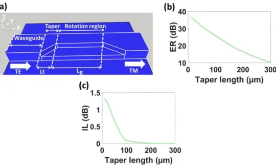
We now consider the full polarization rotator schematically shown in Fig. 3(a), comprising input and output waveguides, tapers and rotator waveguide section. The input and output waveguides and the rotator waveguide section have a width of W = 5 µm and etch depth H = 4 µm. The tapers, of length Lt, are designed to minimize insertion loss due to mode mismatch between the input/output waveguide and the rotation waveguide. The rotation section has a length LR and the cross-section optimized in the design procedure outlined in the previous section. We studied the influence of the taper length on the rotator performance by means of EME propagation simulations. We calculate extinction ratio (ER) and insertion loss (IL) as following: 10 10 log ( TE TM), TE TE T ER T − − = (5) 10 10 log ( TE TM TE TE), IL= − T − +T − (6)
where TTE-TM denotes the calculated transmittance for transverse electric (TE) to transverse
magnetic (TM) polarization and TTE-TE the transmittance for TE to TE polarization, from the
function of the taper length, Lt, for a wavelength of 7.5 µm. Note that propagation through the taper will induce a phase shift that needs to be compensated in the rotator section. Hence, for each value of the taper length, the length of the rotation region, LR, was adjusted to maximize the ER. As can be seen, increasing the taper length reduces the insertion losses. On the other hand, long tapers result in an uneven excitation of the hybrid modes in the rotator waveguide that degrades the attainable ER. Therefore, we chose Lt = 100 µm and LR = 1660 µm as a tradeoff to ensure ER above 25 dB and IL below 0.1 dB.
Fig. 3. (a) Schematic view of the polarization rotator. (b) Extinction ratio as a function of the taper length calculated for 7.5 µm wavelength. (c) Insertion loss as a function of the taper length calculated for 7.5 µm wavelength.
We have calculated the wavelength dependence of the ER and IL for the proposed rotator, with Lt = 100 µm and LR = 1660 µm. We considered a propagation loss of 2-3 dB/cm, determined in a previous experimental study [19], including its spectral dependence. As shown in Figs. 4(a) and 4(b) the polarization rotator yields a peak ER of 30 dB with IL below 0.5 dB. The rotator shows a remarkable broadband operation with an extinction ratio of 15 dB and 10 dB for bandwidths of 2 µm and 3.8 µm, respectively while the insertion loss is lower than 1 dB in the wavelength range from 5 µm to 9µm. This is a substantial improvement compared to previously reported polarization rotators in the near-infrared [41,43,44].
For comparison, in Fig. 4, we also show the ER for the rotator waveguide geometry a2 (see Fig. 1(b)), with Lt = 30 µm and LR = 2000 µm. This geometry leads to a maximum ER of 42 dB which is higher than for the flattened hybridization geometry. However, this geometry yields a substantially narrower wavelength range, with 15 dB and 10 dB ER bandwidth of only 240 nm and 310 nm, respectively.
Fig. 4. (a) Polarization rotator extinction ratio as a function of the wavelength. Broadband design (geometry c2, green curve). Red curve shows the ER of a rotator with no hybridization flattening (geometry a2). Cyan dashed and solid lines indicate ER = 15 dB and ER = 10 dB, respectively. (b) Insertion loss in the rotator as a function of the wavelength for the optimized geometry c2.
4. Optimizing fabrication tolerances and bandwidth by tapered design
An important parameter to be considered for a polarization rotator is its tolerance to fabrication errors. Considering all possible waveguide dimensions variations, we found that the critical parameter affecting the ER is the etch depth J. The rotator designed in the previous section requires etch depth fabrication accuracy better than ± 50 nm for ER>10 dB over a bandwidth of 3.8 µm. While tolerances of ± 50 nm are well within the capabilities of standard fabrication processes for silicon wire waveguides, it is difficult to achieve this accuracy for Ge-rich Si-Ge platform with the etch depth of a few micrometers. To overcome this limitation, we propose to implement a rotator waveguide section with a tapered width KN (see Fig. 5(a)). Tapered rotators are known to improve fabrication tolerances and bandwidth because the width variation in the tapered rotation region partially compensates the deviations from the geometry with the tilt angle of φ = 45° [44,45]. Here we start with the structure designed in the previous sections and implement tapering by applying an offset -f in the beginning of the rotation region and + f at the end of the rotation region KN. The taper length
Lt is maintained 100 µm. The EME propagation simulations have been performed for f = 100
nm, 200 nm, 300 nm and 400 nm, for wavelengths between 4 µm and 9 µm. For each offset value, the rotator length, LR, is optimized to maximize the ER. The value of f = 200 nm has been chosen as a good compromise between ER and tolerances to fabrication errors. The wavelength dependence of the optimized design (f = 200 nm, LR = 1695 µm) is shown in Fig. 5(b). This design yields a maximum ER of 27 dB at the peak wavelength, an ER higher than 15 dB in a bandwidth of 1.8 µm (between 6.5 and 8.3 µm wavelength) and an ER higher than 10 dB for the wavelength range 4.3 – 8.65 µm. Interestingly, this configuration can support fabrication errors up to ± 100 nm on all dimensions of the rotation region while ensuring an operational bandwidth of at least 600 nm (for ER>15 dB), (ii) an ER>10 dB for the wavelength range 5 – 8 µm. This is shown in Fig. 5(b), specifically the ER as a function of the wavelength for etch depth errors of ± 100 nm (from the nominal value JN = 1.73 µm). It can also be seen that the impact of under-etching affects more the 15 dB bandwidth (i.e. the spectral range with ER>15 dB) than over-etching. This is a two-fold tolerance improvement compared to the non-tapered design. If we compare the bandwidth of the tapered rotator design to the original, we gain 550 nm on 10 dB bandwidth which is already bigger than 3.5 µm and we lose 200 nm on 15 dB bandwidth. Consequently, the tapered design offers two advantages: simultaneous improvement of bandwidth and of fabrication tolerance.
Fig. 5. (a) Schematics of the tapered polarization rotator. KN = 3.09µm. (b) Extinction ratio as a function of the wavelength for nominal tapered rotator with f = 200 nm (green curve) and the effect of over-etching (orange curve) and under-etching (blue curve).
5. Conclusion
In summary, we designed an ultra-wideband polarization rotator based on Ge-rich SiGe waveguide platform in the mid-IR wavelength range with an unprecedented bandwidth. An extinction ratio of at least 15 dB is obtained over a wavelength range of 2 µm, or 10 dB over 3.8 µm wavelength range. This was achieved by hybridization flattening, making optical axis tilt wavelength independent over a broad spectral range by judicious optimization of geometrical parameters. The geometry was optimized by modal analysis and EME simulations were performed to evaluate the device performances. The polarization rotator tolerance to fabrication errors has been studied and a tapered Ge-rich SiGe rotator with fabrication tolerances up to ± 100 nm was designed. The tapered rotator preserves the ultra-wideband behavior with losses below 1 dB in the full operational range with an ER exceeding 15 dB (10 dB) within 1.8 µm (3 µm) bandwidth. This study paves the way for implementing on-chip polarization management in the mid infrared spectral region over a broadband wavelength range.
Funding
European Research Council (ERC) under the European Union’s Horizon 2020 research and innovation program (639107-INsPIRE).
References
1. A. B. Seddon, “A prospective for new mid-infrared medical endoscopy using chalcogenide glasses,” Int. J. Appl. Glass Sci. 2(3), 177–191 (2011).
2. C. Yu, A. Ganjoo, H. Jain, C. G. Pantano, and J. Irudayaraj, “Mid-IR biosensor: detection and fingerprinting of pathogens on gold island functionalized chalcogenide films,” Anal. Chem. 78(8), 2500–2506 (2006). 3. L. Labadie and O. Wallner, “Mid-infrared guided optics: a perspective for astronomical instruments,” Opt.
Express 17(3), 1947–1962 (2009).
4. Z. Han, P. Lin, V. Singh, L. Kimerling, J. Hu, K. Richardson, A. Agarwal, and D. T. H. Tan, “On-chip mid-infrared gas detection using chalcogenide,glass waveguide,” Appl. Phys. Lett. 108(14), 141106 (2016). 5. C. Gilles, L. J. Orbe, G. Carpintero, G. Maisons, and M. Carras, “Mid-infrared wavelength multiplexer in
InGaAs/InP waveguides using a Rowland circle grating,” Opt. Express 23(16), 20288–20296 (2015). 6. S. Roux, L. Cerutti, E. Tournie, B. Gérard, G. Patriarche, A. Grisard, and E. Lallier, “Low-loss
orientation-patterned GaSb waveguides for mid-infrared parametric conversion,” Opt. Mater. Express 7(8), 3011–3016 (2017).
7. H. Lin, L. Li, Y. Zou, S. Danto, J. D. Musgraves, K. Richardson, S. Kozacik, M. Murakowski, D. Prather, P. T. Lin, V. Singh, A. Agarwal, L. C. Kimerling, and J. Hu, “Demonstration of high-Q mid-infrared chalcogenide glass-on-silicon resonators,” Opt. Lett. 38(9), 1470–1472 (2013).
8. A. Gutierrez-Arroyo, E. Baudet, L. Bodiou, J. Lemaitre, I. Hardy, F. Faijan, B. Bureau, V. Nazabal, and J. Charrier, “Optical characterization at 7.7 µm of an integrated platform based on chalcogenide waveguides for sensing applications in the mid-infrared,” Opt. Express 24(20), 23109–23117 (2016).
9. G. Z. Mashanovich, M. M. Milošević, M. Nedeljkovic, N. Owens, B. Xiong, E. J. Teo, and Y. Hu, “Low loss silicon waveguides for the mid-infrared,” Opt. Express 19(8), 7112–7119 (2011).
10. J. S. Penadés, A. Sánchez-Postigo, M. Nedeljkovic, A. Ortega-Moñux, J. G. Wangüemert-Pérez, Y. Xu, R. Halir, Z. Qu, A. Z. Khokhar, A. Osman, W. Cao, C. G. Littlejohns, P. Cheben, I. Molina-Fernández, and G. Z. Mashanovich, “Suspended silicon waveguides for long-wave infrared wavelengths,” Opt. Lett. 43(4), 795–798 (2018).
11. T. Baehr-Jones, A. Spott, R. Ilic, A. Spott, B. Penkov, W. Asher, and M. Hochberg, “Silicon-on-sapphire integrated waveguides for the mid-infrared,” Opt. Express 18(12), 12127–12135 (2010).
12. Y. Zou, S. Chakravarty, P. Wray, and R. T. Chen, “Mid-infrared holey and slotted photonic crystal waveguides in silicon-on-saphire for chmical warfare simulant detection,” Sens. Actuators B Chem. 221, 1094–1103 (2015). 13. M. Nedeljkovic, J. S. Penades, V. Mittal, G. S. Murugan, A. Z. Khokhar, C. Littlejohns, L. G. Carpenter, C. B.
E. Gawith, J. S. Wilkinson, and G. Z. Mashanovich, “Germanium-on-silicon waveguides operating at mid-infrared wavelengths up to 8.5 μm,” Opt. Express 25(22), 27431–27441 (2017).
14. A. Malik, M. Muneeb, S. Pathak, Y. Shimura, J. Van Campenhout, R. Loo, and G. Roelkens, “Germanium-on-silicon mid-infrared arrayed waveguide grating multiplexers,” IEEE Photonics Technol. Lett. 25(18), 1805–1808 (2013).
15. A. Malik, M. Muneeb, Y. Shimura, J. Van Campenhout, R. Loo, and G. Roelkens, “Germanium-on-Silicon Planar Concave Grating Wavelength (de)multiplexers in the mid-Infrared,” Appl. Phys. Lett. 103(16), 161119 (2013).
16. A. Malik, S. Dwivedi, L. Van Landschoot, M. Muneeb, Y. Shimura, G. Lepage, J. Van Campenhout, W. Vanherle, T. Van Opstal, R. Loo, and G. Roelkens, “Ge-on-Si and Ge-on-SOI thermo-optic phase shifters for the mid-infrared,” Opt. Express 22(23), 28479–28488 (2014).
17. M. Brun, P. Labeye, G. Grand, J.-M. Hartmann, F. Boulila, M. Carras, and S. Nicoletti, “Low loss SiGe graded index waveguides for mid-IR applications,” Opt. Express 22(1), 508–518 (2014).
18. M. Sinobad, C. Monat, B. Luther-davies, P. Ma, S. Madden, D. J. Moss, A. Mitchell, D. Allioux, R. Orobtchouk, S. Boutami, J.-M. Hartmann, J.-M. Fedeli, and C. Grillet, “Mid-infrared octave spanning supercontinuum generation to 8.5 μm in silicon-germanium waveguides,” Optica 5(4), 360–366 (2018).
19. J. M. Ramírez, Q. Liu, V. Vakarin, J. Frigerio, A. Ballabio, X. Le Roux, D. Bouville, L. Vivien, G. Isella, and D. Marris-Morini, “Graded SiGe waveguides with broadband low-loss propagation in the mid infrared,” Opt. Express 26(2), 870–877 (2018).
20. J. M. Ramírez, V. Vakarin, J. Frigerio, P. Chaisakul, D. Chrastina, X. Le Roux, A. Ballabio, L. Vivien, G. Isella, and D. Marris-Morini, “Ge-rich graded-index Si1-xGex waveguides with broadband tight mode confinement and
flat anomalous dispersion for nonlinear mid-infrared photonics,” Opt. Express 25(6), 6561–6567 (2017). 21. V. Vakarin, J. M. Ramírez, J. Frigerio, A. Ballabio, X. Le Roux, Q. Liu, D. Bouville, L. Vivien, G. Isella, and D.
Marris-Morini, “Ultra-wideband Ge-rich silicon germanium integrated Mach-Zehnder interferometer for mid-infrared spectroscopy,” Opt. Lett. 42(17), 3482–3485 (2017).
22. V. Vakarin, J. Ramírez, J. Frigerio, Q. Liu, A. Ballabio, X. Le Roux, C. Alonso-Ramos, G. Isella, P. Cheben, W. N. Ye, and L. Vivien, “Wideband Ge-Rich SiGe Polarization-Insensitive Waveguides for Mid-Infrared Free-Space Communications,” Appl. Sci. (Basel) 8(7), 1154 (2018).
23. Q. Liu, J. M. Ramírez, V. Vakarin, X. Le Roux, A. Ballabio, J. Frigerio, D. Chrastina, G. Isella, D. Bouville, L. Vivien, C. A. Ramos, and D. Marris-Morini, “Mid-infrared sensing between 5.2 and 6.6 µm wavelengths using Ge-rich SiGe waveguides,” Opt. Mater. Express 8(5), 1305–1312 (2018).
24. Q. Liu, J. M. Ramírez, V. Vakarin, X. Le Roux, C. Alonso-Ramos, J. Frigerio, A. Ballabio, E. Talamas Simola, D. Bouville, L. Vivien, G. Isella, and D. Marris-Morini, “Integrated broadband dual-polarization Ge-rich SiGe mid-infrared Fourier-transform spectrometer,” Opt. Lett. 43(20), 5021–5024 (2018).
25. S. Serna, V. Vakarin, J. M. Ramírez, J. Frigerio, A. Ballabio, X. Le Roux, L. Vivien, G. Isella, E. Cassan, N. Dubreuil, and D. Marris-Morini, “Nonlinear Properties of Ge-rich Si1-xGex Materials with Different Ge
Concentrations,” Sci. Rep. 7(1), 14692 (2017).
26. D. Marris-Morini, V. Vakarin, J. M. Ramírez, Q. Liu, A. Ballabio, J. Frigerio, M. Montesinos, C. Alonso-Ramos, X. Le Roux, S. Serna, D. Benedikovic, D. Chrastina, L. Vivien, and G. Isella, “Germanium-based integrated photonics from near- to mid-infrared applications,” Nanophotonics 7(11), 1781–1793 (2018). 27. W. Cao, D. Hagan, D. J. Thomson, M. Nedeljkovic, C. G. Littlejohns, A. Knights, S.-U. Alam, J. Wang, F.
Gardes, W. Zhang, S. Liu, K. Li, M. S. Rouifed, G. Xin, W. Wang, H. Wang, G. T. Reed, and G. Z.
Mashanovich, “High-speed silicon modulators for the 2 μm wavelength band,” Optica 5(9), 1055–1062 (2018). 28. R. Kou, T. Hatakeyama, J. Horng, J.-H. Kang, Y. Wang, X. Zhang, and F. Wang, “Mid-IR broadband
supercontinuum generation from a suspended silicon waveguide,” Opt. Lett. 43(6), 1387–1390 (2018). 29. M. Yang, Y. Guo, J. Wang, Z. Han, K. Wada, L. C. Kimerling, A. M. Agarwal, J. Michel, G. Li, and L. Zhang,
“Mid-IR supercontinuum generated in low-dispersion Ge-on-Si waveguides pumped by sub-ps pulses,” Opt. Express 25(14), 16116–16122 (2017).
30. S.-P. Chiang, C.-T. Wang, J.-Y. Lai, C.-L. Tsai, C.-C. Li, H.-C. Jau, C.-T. Hou, S.-D. Yang, and T.-H. Lin, “Broadband mid-infrared polarization rotator based on optically addressable LCs,” Opt. Express 25(14), 16123– 16129 (2017).
31. J. Guo, A. Rostamian, S. Chakravarty, H. Yan, C.-J. Chung, E. Heidari, and R. Chen, “Mid-Infrared Silicon-on-Sapphire Polarization Rotator,” in CLEO 2018 (Optical Society of America, San Jose, 2018), SF3J.6.
32. W. He and E. Cassan, “Mid-infrared polarisation rotator based on an asymmetric Ge-strip-on-si waveguide,” IET Optoelectron. 8(6), 197–202 (2014).
33. H. Xu and Y. Shi, “Ultra-broadband silicon polarization splitter-rotator based on the multi-mode waveguide,” Opt. Express 25(15), 18485–18491 (2017).
34. D. Chen, X. Xiao, L. Wang, W. Liu, Q. Yang, and S. Yu, “Highly efficient silicon optical polarization rotators based on mode order conversions,” Opt. Lett. 41(5), 1070–1073 (2016).
35. J. Fan, C. Huang, and L. Zhu, “A compact, broadband slot waveguide polarization rotator,” AIP Adv. 1(4), 042136 (2011).
36. A. Majumder, B. Shen, R. Polson, and R. Menon, “Ultra-compact polarization rotation in integrated silicon photonics using digital metamaterials,” Opt. Express 25(17), 19721–19731 (2017).
37. H. Takahashi, Y. Hibino, and I. Nishi, “Polarization-insensitive arrayed-waveguide grating wavelength multiplexer on silicon,” Opt. Lett. 17(7), 499–501 (1992).
38. M. O. D. E. Solutions, Lumerical Solutions Inc. http://www.lumerical.com/.
39. Q. Liu, J. M. Ramírez, V. Vakarin, X. Le Roux, J. Frigerio, A. Ballabio, E. T. Simola, C. Alonso-Ramos, D. Benedikovic, D. Bouville, L. Vivien, G. Isella, and D. Marris-Morini, “On-chip Bragg grating waveguides and Fabry-Perot resonators for long-wave infrared operation up to 8.4 µm,” Opt. Express 26(26), 34366–34372 (2018).
40. J. M. Ramírez, Q. Liu, V. Vakarin, X. Le Roux, J. Frigerio, A. Ballabio, C. Alonso-Ramos, E. T. Simola, L. Vivien, G. Isella, and D. Marris-Morini, “Broadband integrated racetrack ring resonators for long-wave infrared photonics,” Opt. Lett. 44(2), 407–410 (2019).
41. M. R. Watts and H. A. Haus, “Integrated mode-evolution-based polarization rotators,” Opt. Lett. 30(2), 138–140 (2005).
42. Y. Fei, L. Zhang, T. Cao, Y. Cao, and S. Chen, “Ultracompact polarization splitter-rotator based on an asymmetric directional coupler,” Appl. Opt. 51(34), 8257–8261 (2012).
43. C. Alonso-Ramos, S. Romero-García, A. Ortega-Moñux, I. Molina-Fernández, R. Zhang, H. G. Bach, and M. Schell, “Polarization rotator for InP rib waveguide,” Opt. Lett. 37(3), 335–337 (2012).
44. Y. Xiong, D.-X. Xu, J. H. Schmid, P. Cheben, S. Janz, and W. N. Ye, “Fabrication tolerant and broadband polarization splitter and rotator based on a taper-etched directional coupler,” Opt. Express 22(14), 17458–17465 (2014).
45. Y. Ding, L. Liu, C. Peucheret, and H. Ou, “Fabrication tolerant polarization splitter and rotator based on a tapered directional coupler,” Opt. Express 20(18), 20021–20027 (2012).