AN APPROACH TO THE TWO DIMENSIONAL, IRREGULAR. CUTTING STOCK PROBLEM
by
RICHARD C. ART, JR.
Submitted in Partial Fulfillment of the Requirements for the Degree of Bachelor of Science
at the
MASSACHUSETTS INSTITUTE OF TECHNOLOGY
September, 1966
Signature redacted
Signature of Author... ... ...
Sloan School of 1\'anagement, August 29, 1966
Signature redacted
Certified by... . ... FesiA Supervisor
Signature redacted
Accepted by... . ...Chaii n, Depar ental Committee on Theses
NST
F
48
ABSTRACTAN APPROACH TO THE TWO DIMENSIONAL, IRREGULAR CUTTING STOCK PROBLEM
by
Richard Carl Art, Jr.
Submitted to the Alfred P. Sloan School of Management on August 29,
1966 in partial fulfillment of the requirements for the degree of
Bachelor of Science.
This paper is a report on an investigation of the practicability of computerizing the solution to the problem of laying out the pieces of a garment pattern in the most efficient manner. This process is known to the garment industry as pattern marking. Specifically the investigation sought a method of solving this problem which, though not optimum, would indicate a means of achieving results which would be commercially competitive with present industry practice.
The first section of this paper gives an explication of the prob-lem and present methods of producing results. Section two is a short description of the methods used throughout the paper for representing the pieces and formalizing the problem. The third section is devoted to a discussion of a variety of techniques for approaching the problem as a whole, and dealing with certain subfroblems which arise within the larger framework. The fourth section describes a particular technique which was programmed in the FORTRAN IV language for the IBM 7094. The fifth, and concluding, section discusses: 1) the areas of application for the techniquesdescribed, and 2) the further investigation which would be required to advance the "state of the art" to an abstract statement and solution of the problem.
Thesis advisor: John D. C. Little
Professor William C. Greene Secretary of the Faculty
Massachusetts Institute of Technology Cambridge, Massachusetts 02139
Dear Professor Greene:
In accordance with the requirements for graduation, I herewith submit a thesis entitiled "An Approach to the Two Dimensional, Irregular Cutting Stock Problem!'
I wish to express my deep indebtedness to the IBM Cambridge Scientific Center under the direction of Norman L. Rasmussen which has financially supported this investigation in its entirety. Without the
support of the Center's staff this work would have been impossible. I also wish to thank Professor John D. C. Little for undertaking super-vision of this work, and Mr. R. L. Schmalensee for his suggestions regarding the drafts of this paper. Dr. John. F. Pierce of the
Scientific Center staff deserves my especial gratitude for his patient encouragement of this project during the fourteen months in which work was in progress.
Sincerely,
Signature redacted
Richard C. Art, Jr.TABLE OF CONTENTS
Section I: Problem Description ... 2
Section II: Representation of Pieces and Envelopes. .. .. ... 4
Section III: Solution Techniques... 9
Section IV: The Method Programmed ...17
Section V: Futher Considerations ... .24
Appendix I: Lengths of Markers ... 30
Appendix II: Sample Marker Produced by Algorithm... 31
-1-
-2-SECTION I
Problem Description:
The general problem is one of arranging a number of pieces constituting several complete garments in such a way that they consume a minimum amount of material of a given width. Although there are no restrictions on the shapes or sizes of these pieces, cer-tain "ground rules" must be followed in laying out the pattern mark-er. First, each piece must lie entirely within the width of the mat-erial, and must not overlap any other piece. Second, all of the pieces must lie between two parallel lines drawn perpendicular to the ''grain" of the material, which define the length of the marker. Third, the "grain" of the piece must be aligned with the grain of the material
from which the garment will be cut. Fourth, due to a difference in the finish of the two sides of the material, pieces must be placed "face up. "
It should be noted that this is a limited case of the more gen-eral problem of placing a set of figures in a plane so as to minimize circumscribed area used. The more general problem might not have any of the above restrictions other thanthat of non-overlap, but it is usually stated with some constraints, e. g. that the area in which
pieces must be placed is of fixed width.
Pattern layout (or "marking" as it is called in the industry) is presently performed by men using either full size cardboard templates
pro-
-3-cess the marker drawn is enlarged by pantograph to give the required full sized marker. The more experienced men performing this task waste on the order of eight percent and the less experienced approx-imately twelve percent. This waste is the area between the pieces which can not be used. The waste figures for specific segments of the industry vary widely from the six percent figure achieved in the n-n's work clothes sector to the twenty-four percent appropriate for the lin-gerie sector. Presently the garment industry is experiencing great pressure due to the lack of qualified men for this task. Not only is the waste figure for new talent significantly higher, but also those presently employable are overburdened to the point where firms choose to waste cloth rather than have markers redrawn to fit new widths of material, etc.
As a result, a computerization of a solution to this problem
would be of great value in alleviating what is rapidly becoming a rather
urgent set of circumstances. Classical methods to solve the knapsack problem offer little when dealing with the complex shapes involved here. Beyond this there has been little previous effort at solution by algorithmic or heuristic methods.
-4-SECTION II
Representation of Pieces
Each of the pieces of garment can be represented by an order-ed set of line segments which approximate the piece to any desirorder-ed accuracy. Since the seamstresses who sew the actual garments are not accurate to more than 1/32", attempts to reduce the tracking error to less than this are rather futile. In the solution described here, the set of end points for these line segments is used as the means of describ-ing any given piece. There are four important characteristecs of these sets of points as used in this method:
1.
The grain of the material is taken to be parallel to the x-axis; (width of the material is therefore along the y-axis).2. The piece is made to lie wholly within the first quadrant so
that there are no negative values for either x or y.
3. There is at least one point in the set for which the x value is
zero and one for which the y value is zero, and
4. The set of points begins and ends with the point with the great -est y value for which the x value is zero and lists the points on the per-imeter in a counter-clockwise direction. The reference point for each piece is this redundantly entered first and last point. Figure 1. is a sample piece from one of the garments used as test data reduced to one-tenth actual size. Figure 2. is the same piece represented by line segments with the points used indicated by small dots.
-5-In this method, the convex representation of the pieces was used. (Figure 3, is the convex representation of the piece in Figures 1. and
2.). Convex is used here in the traditional geometric sense as applied to polygons in a plane.
Figure 3. Convex representation
The advantages of using the convex pieces rather than the "full" representation were many. The most important of these are: 1)
the number of points required is somewhat less than half in the average case; 2) the computation time required for a solution with the convex pieces is less than one-tenth that which would be required for a solution with the "full" pieces, 3) in practice one rarely finds that the convex pieces would overlap if they had been used instead of the full pieces, and 4) that the so called small pieces not used in the solution are those which are overlapped, and that they adequately fill the area temporarily
"wasted" by making the larger pieces convex. For these reasons solutions were determined using convex pieces; these being replaced with the full pieces for output purposes only.
The requirement that the grain of each piece be aligned with the grain of the material allows the one laying out a marker to place the piece rotated 1800 from whatever is considered the "normal" position.
-6-Envelope s:
What is referred to here as the Envelope for a piece is the locus of points traced by the reference point as the piece is "moved" so as to be physically bounded by either the edge of the material or other pieces which have been placed. In this manner, the Envelope is the perimeter of that area within which the reference point can validly fall. It is represented as an ordered set of x, y pairs which
are the end points of the line segments comprising this locus. Since both the pieces and the edge of the material can be represented
ex-clusively with line segments, the envelope can likewise be so repre-sented. The set of points begins at the lower right (a point with an arbitrarily large x value) and traces the locus in a clockwise direc-tion ending in the upper right. Figure 4. shows the envelope for the
same sample piece used previously in the initial state where no pieces have yet been placed. In the initial state the rectangular envelope indicates that the piece may be placed anywhere within the borders of the material. EDGE OF
MAT'L
ENVELOPE
PIECE Figure 4.
-7-Placement of Pieces:
The placement of some piece affects the area in which other pieces may be placed by precluding their placement in the area "taken "
by the placed piece. This can be represented by a modification of the Envelopes for those pieces which remain to be placed. Since by definition the Envelope represents the physical limits of the placement of a piece, the Envelope which was valid prior to the placement of a piece can be altered only in that region where the two pieces (the placed one and the one connected with the envelope under discussion) would be in contact. As a result, we can find the required alteration
by findirg the partial Envelope which would be generated by
concern-ing ourselves with these two pieces only. By replacing a section of
the old Envelope with a portion of the partial one as appropriate, (see Figure 5. where the old Envelope for piece E, the partial envelope generated by placement of piece P, and the resultant new envelope are indicated) we avoid having to completely regenerate the envelope after each successive piece is placed.
OLD AND N6W E NVVL of' PPIARTL AND ENVELOPE OLD elqVeLOPE Figure 5.
-8-In some cases, the area in which the partial Envelope falls has been previously precluded by prior placement and no modification of the existing Envelope is required. Figure 6. ills trates this case with rectangles used for examples.
VeLACED PlcG
*V..fP. PT. PReVI1VSL.Y wVu&.OP
0,PLACMeb Pace Plfce
Figure 6.
The case of no modification of-the Envelope for piece E
I
-9-SECTION III
Solution techniques:
The previous section gives one a means of representation and a general frame of reference for the problem, but the open question of techniques to be used for selecting and placing pieces remains. There are an infinite number of positions for each piece. Therefore to render this problem soluble it is necessary to make a number of rather categorical assumptions about placement, some of which will be reviewed in Section V.
Placement of pieces will be sequential and deterministic. It is assumed throughout this study that each piece will be placed such that it is in contact with the edge or a previouly placed piece, i. e., on the envelope. Given this placement scheme, plakcement "in the middle" implies that some future use is to be made of the available area that makes it advantageous not to place this piece at some point on its envelope. "Future use" implies that there is some number of placements which are logically prior to the one in question. If they are logically prior, then it stands to reason that they ought to be actually prior, hence allowing the piece to be placed on the modified envelope existing at a later time. Therefore, placement "in the middle" is ignored in spite of any hidden advantages it may have.
AlhJbugh there is certainly a trade-off between the solution time and the quality of solution obtained, we choose to reject the class of solutions based on having some predetermined order of placement which does not take the effect of prior placements into account, e. g. placing pieces from largest to smallest. Such schemes would find the best place for the first piece (however we choose to define best), place it, find the best place
-10-for the second piece and so on. Concern for the best placere nt of a piece neglects the overriding concern which one must have for filling the total area efficiently. The case may be that none of the best place-ments for individual pieces fills an area which "needs filling. "
Having decided that it is best to place pieces at the edge, the next question is whether the solution should work from one end toward the other (e. g. from left to right), or from both ends toward the middle (i. e. a double-ended solution). There are several reasons for reject-ing the two-ended approach. The use of this approach re~quires that when the two partial solutions begin to affect one another we cannot
"force" the ends to mesh in the middle. If the solution is iterative and works on a branch-and-bound basis, we know fairly early that a branch must be taken. If, on the other hand, the solution is nonitera-tive, the difficulties in the middle are unresolvable; hence, all we know is that using this particular set of selection rules, we cannot achieve a solution for this length. This would imply that a longer marker must be used. The difficulty persists to the extent that there is no obvious way of insuring meshing in the middle which does not also imply very low efficiency in this region.
In choosing to pursue a single-ended approach, it is obvious that symmetry allows free choice of the end from which we will work. The left edge was arbitrarily chosen as the beginning of the marker. One piece must touch this edge, and in practice several are forced to do so.
Placement of pieces so that they touch the top or bottom edge but not the left edge on another piece is rejected for the same reason that place-ment in the middle is. This process of elimination gives the portion of
A
-11-the envelope on -11-the left-most extreme (intially coincident with a portion of the edge) as the range of possible points for placement.
Placement of the initial pieces follows the same line of reasoning used above, the result being that the first pieces placed should touch both the left edge and either the top or the bottom edge. The top and the bottom are equivalent starting points in the same sense that the
right-and left-hand sides are. The arbitrary choice of the bottom edge was made.
Even under a framework as restrictive as that established above, the problem of deciding how pieces should be selected remains.
The waste in any solution is the sum of the area between the pieces. If we are to minimize the overall waste, it seems reasonable that we try to minimize the waste between individual pieces as they are placed. The jigsaw puzzle throws some light on the theory which has been used. In the jigsaw puzzle there is no waste whatsoever. The edgesof each piece are coincident with those of its neighbors or form part of the bor-der. Experience with interlocking puzzles teaches us that straight edges appear only on the border; hence, those pieces that form the border are easily identified. Moreover, a piece with two straight edges is iden-tified as a corner. The similarities between the jigsaw problem and the
garment pattern problem are not so great that a solution to the latter is obvious, but the similarities give rise to some useful techniques for dealing with this problem.
It would be an extremely unusual case if we were to find that the garment pieces were to fit together with no waste. The author has
-12-The jigsaw puzzle gives us three indicia of a "good " solution. One, in every case there are some pieces with straight edges parallel to the grain line. In general it seems logical that these straight edges be placed on the physical edge of the material, thereby recucing waste
at the edge. Two, some of these pieces will have right angle corners. In most cases the bigger of the pieces are the ones which exhibit the above properties. In the case of jigsaw pieces, fairly large collections of interlocking pieces can be found long before their place in the puz-zle as a whole is known; this leads us to the next point. Three, that although pieces of the garment(s) will perhaps not "interlock, " there are combinations of pieces or "netapieces" which are most efficiently considered together.
Meta-pieces take advantage of highly visual qualities of the pieces which are rather difficult to deal with numerically. They are generally efficient in that they have highly coincident edges. They may als.o use contours of the pieces in a manner which is precluded when convexed pieces are used. This utilization of space which would otherwise be wasted has often been noted as a means of improving solutions with
convex pieces . Furthermore, placement of meta-pieces is a means of rapidly disposing of a number of pieces and thereby shortening sol-ution time.
When using meta-pieces it is necessary also to consider the pieces of which they are composed inasmuch as there is no assurance that the meta-pieces will be more efficient in terms of the overall solution. Although quite useful in hand simulation, meta-pieces were not used in the method programmed; therefore, the rules for deciding when one
-13-should "break up" a meta-piece to use the individual pieces have not been exactly formulated. However, the decision must generally consider these factors: 1) the probable waste of the meta-piece, i; e., the probable waste of the meta-piece when placed, plus the unavoidable waste implicit in form-ing the meta-piece, 2) the probable waste of the pieces composing the meta-piece (i. e., the sum of the waste in this particular placement and the probable waste of the other pieces when placed), and 3) the waste involved in the "next best," alternative placement which would not break up the meta-piece,
Hand simulation indicates that a nM ta-piece should be broken up when the individual pieces can be efficiently placed and where the cost of alternatives is high. In terms of abstract formulations of this rule, the form of the rule is probably best derived by heuristic methods. Ex-perience gives the human solver the concept in the first place and an intuitive sense of when meta-pieces should be broken up or saved.
The class of solutions indicated by the above remarks proceed from left to right. The envelopes give us the values of the left-most points at which each of the pieces can be placed. In the interest of being as efficient as possible, the concepts derived from the analogy with the jigsaw puzzle indicate some of the techniqueswhich one should employ in selecting and placing pieces. Since we have discounted the class of solutions which look for the"best" place for each piece on a step-by-step basis, it must be remarked that a modified form of this concept can be usefully employed. Frequently the left-most "point" of the Envelope is
a point
not/at all but rather a line. If one measures the waste in the placement for the points on this line, one can make a sounder choice of where to
-14-place the piece than if one assumes that one end point is best. Another conceptualization of waste is the reason for looking at all of the points on this line.
In addition to looking at waste as the space between the pieces, we can also conceive of it in terms of how the placement of a particular piece affects the possible placement of the remaining pieces. A
place-ne nt which appears efficient at first may actually be rather iplace-nefficient if one considers the area which has been excluded from further use. This area may be larger than the piece itself because of the geometry of the
solution. A piece placed a few inches from the edge may not allow place-ment between it and the edge and therefore it is "wasting" this space.
Although the Envelopes indicate how far to the left the pieces can be placed and we are able to me-asure the.waste of any liarticular piace-ment, there are some additional considerations which should be taken in-to account. We can assure that the left side of the marker is quite effi-cient, but the reduced number of choices as one moves to the right gives us a progressively less efficient solution. This difficulty is the analogue to the "meshing" problem of the two-ended solution. We can always ob-tain a solution, but the length may exceed that desired. Therefore, as the solution is progressing, we must look to the area which the remain-ing pieces require as a general indication of the length of the solution. Also the minimum possible length of the solution is indicated by the
larg-est sum obtained by addition of the minimum x for an Envelope to the length of the corresponding piece. This latter measure indicates the
sometimes fatal result of leaving a long piece unplaced until the end of the solution.
-15-The area of a piece is a consideration to the extent that, other things being equal, a bigger piece should be placed before a smaller one. The advantage results from the generally wider range of placements for the smaller pieces. That is, the probability of finding another place which is as good or better for a big piece is smaller than that for a small piece. Also the opportunity to "fill in around" a larger piece speaks for its placement.
-16-To summarize the above considerationr, there are five concepts which should be balanced in the placement and selection rules:
1) The minimum x-value on the Envelope for the piece.
2) The waste of this placement.
3) The "trade-off" if this placement would break up a meta-piece.
4) The area of the piece.
5) The amount by which this placement will certainly lengthen the marker.
The actual form of the sets of rules is limited by one's imagination only, but in the author's experience these five are the most important.
-17-SECTION IV The Method Programmed:
In the method described below a rather simple version of the problem is attacked. No consideration is given to the problem of repetitive designs in the fabric (e.g., stripes); a uniform material (i. e., a solid color) is assumed. The pieces will all be face up and hold rigidly to the parallel grain constraint. Lacking previous work which would indicate how this problem might be attacked, it was decided to seek a solution, which though not optimum, would indicate a means of achieving results which would be commercially competitive with markers laid out by humans. To this end a major portion of this work was devoted to developing an approach that would offer results meriting further pursuit. It was decided that it would be best to develop a non-iterative algorithm for the placement of pieces which would be amenable to future extention to more sophisticated sets of placement rules if they were indicated.
Selection Rules:
The set of rules used for selecting pieces in their order of place-ment is rather simple. The rules are not the analog of the set which is used by the human who is employed for this purpose, but rather are derived from the author's observation of the process of marking garment patterns and experience in marker making using the set of miniature patterns used as test data. The rules form a hierarchy in which some of the pieces remaining to be placed are excluded from placement by a particular rule, with the remaining ones being tested against successive rules until all but one have been excluded. This is the one placed at a particular stage. In the order in which they presently stand, the rules
-18-1. Select those pieces which have a minimum x-value on the Envelope within a given tolerance value, in inches (an input var-ible, TOL 1) of the minimum available from the pieces remaining. The rule gives pieces which can be placed at the left of the avail-able area.
2. Select from those pieces acceptable under rule 1. those which have an area greater than a fixed fraction (also an input var-iable, TOL 2) of the area of the piece with the maximum area among the pieces acceptable under rule 1. This rule gives us the larger of the pieces which can be placed to the left.
3. Select from those pieces acceptable under rule 2. those with a minimum "probable waste" on the left hand side. Probable waste is obtained in the following manner. The area which lies be-tween the piece and a circumscribing rectangle drawn with sides
par-allel to the edges of the material is divided by the width of the piece. The shaded area in figure 7. illustrates the area in question for a sample piece. The rule gives pieces which are "blunter" on the side which will meet the pieces already placed, or the left edge of the material, whichever is appropriate. This rule is most important in the early stages of placement when the majority of pieces have a min-imum x value equivalent to the left edge of the material; hence a finer rule is required.
Figure 7.
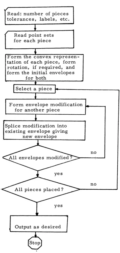
-19-Form the convex represen-tation of each piece, form rotation, if required, and form the initial envelopes
for both Select a piece
Form envelope modification for another piece
Splice modification into existing envelope giving
new envelope
no
All envelopes modified?
yes
no
All pie ce s plac ed ?
yes
Output as desired
Figure 8. General Flow of Programmed Scheme Read: number of pieces
tolerances, labels, etc.
Read point sets for each piece
-20-4. Although rarely needed, the fourth rule is to select from those which have passed all of the above rules that piece which has the lowest y value at the point where the Envelope has minimum x (Cf. rule 1.). This rule gives us a piece in the lower left and tends to give a more compact placement.
Placement of pieces in the solution:
The piece selected by the foregoing rules is placed on the mark-er at the lowest (in y) position for which the Envelope has its mini-mum x value. In this first attempt at computerizing the solution to the general problem, no alteration of this placement method has been attempted. For a discussion of the possiblities for different schemes see the section on general techniques and the one on further consid-erations.
Operation of the method:
Figure 8. is a flow chart of the scheme as programmed, but a brief verbal description seems also appropriate. The point set and number required for each piece along with the width of the material and the two tolerances are input. The point sets are transformed in-to rconvex representation in both "normal" and "rotated" forms, and the intial Envelopes are generated. A piece is selected, the number
required for that piece reduced by one, and the Envelopes for those pieces remaining to be placed modified as discussed above in
Sec-tion II. This process is repeated until the required pieces have been placed, at which time the length of the final marker and the amount of waste are output, and a plot (either full or reduced size) of the
mark-
-21-er can be made. As programmed the method does not iterate, but gives a solution "in one pass" over the pieces.
Test data and experimental results:
The test patterns used for this project were taken from a mark-er obtained from the Seaton Hall Corporation of East Boston, a man-ufacturer of ladies' sportswear. The patterns are for a lady's suit in two sizes. Suit patterns are the most complex occuring in this segment of the industry, each garment being composed of twenty-two pieces. We have been assured that the marker drawn for this pattern is of the highest quality even though its waste for the pieces with which we are concerned is thirteen percent. It is drawn for a width of fifty-eight inches, the width used in the majority of test runs. For the purpose of testing, the smaller pieces (e.g., pocket flaps of about one by four inches) are nglected. It is felt that this is justified on two bases: 1) the smaller pieces can best be used to fill that area opened up by changing from the convex representation used for sol-ution to the full representation from which the garments will be cut, and 2) their inclusion in the problem would be at the cost of a sixty percent degradation of the solution time. These small pieces can be placed by hand in holes opened up or remaining without great incon-venience. Fifteen pieces from each garment were thought to be of sufficient size or importance for inclusion in the test set.
The length of markers obtained in test runs made is summariz-ed in the table in appendix I. Briefly, runs were made at a width of
-22-of TOL 2 -22-of 0. 9, 0. 95, and 1. 0. For these runs the waste can be compared with that achieved by the human solution by assuming that the omitted pieces will fit in the "holes" in the computer solutions. Other scattered runs were made at widths of 56 and 60 inches to con-firm the supposition that the length would decrease if the width were increased and conversely. The time required to read the data and make all computations averaged one minute of 7094 time. Plotted
output was obtained, but from seperate processingand the time re-quired for this is not included as it is highly dependent of the output
device.
As is obvious from the traced copy of an output marker contain-ed in Appendix II, improvements in the results are necessary if com-mercial application is contemplated. The length of this marker, if full-size, would be 137. 5 inches, which is equivalent to a waste of 26 percent if the full representation is used as the base, or of 18. 7 percent if the convex representation is used, The other trail runs at the width of 58 inches yield markers varying in length from 137. 5 to 176. 4 inches with the bulk in the .neighborhood of 142 inches. Most of these solutions are distinct, the ones where the placement is the same being those for which the variation in the tolerance used did not affect the pieces available for placement.
The value of tolerance for minimum x on the Envelope seems to affect the solution only for extreme values. If it is smaller that 0. 1, the selection rules concentrate on finding small interstices open for placement. The marker obtained is usually a patchwork in which the smaller pieces dominate the early stages after the left edge has been
-23-filled, resulting in ineffective placement of larger, wider pieces at later stages. If on the other hand, this tolerance is relaxed to the point where area is the dominant factor, big pieces dominate the early stages in-an equally "unhealthy" manner. The marker obtained in this fashion usually has much wasted area on the left-hand side. The solutions obtained when TOL 1 is between 0. 5 and
5. 0 yeild results which do not bear an obvious relationship to the
particular value of this tolerance. Variations in the tolerance for the ratio of sizes indicate that it is in general most efficient, at least for the sample patterns, to select the biggest of the pieces available. The reason that variation in the tolerances bear only a slight relationship to the quality of results is that each partic-ular pair of tolerances gives one of the 450 solutions which can be obtained by an enumeration of placement order given the placement rules used in the programmed technique. Of course the number
would be much larger if the piece did not have to be placed at the lowest point for which the x value of the Envelope is a minimum, but could be placed any where on the line where the x value is a minimum.
-24-SECTION V
Further Considerations:
The method as programmed is obviously crude in several respects and significant modification is indicated. The lack of a clear relationship between the values of the tolerances and the results obtained indicates that they alone are insufficient indication of the quality under even the most unsophisticated circumstances. The variation of the toleranceon envelope minimum x yielded results which are, at best, merely a reflection of what sound judgement would guess them to be. The variation of tolerance for the relative
area of pieces gives even less direct information, but does point to a few necessary improvements.
Inasmuch as the large pieces in the test problem were nearly rectangular, they fit well into the corners and against one another in a manner consistent with the concepts developed in the jigsaw puzzle analogy. The inexact nature of the correspondance between the concept of area as ' measure,and "goodness of fit" (ala the jigsaw case) is indicated by the poor quality f the solutions. It
appears that if on retains the concept of using the tolerance on min-imum x for the Envelope (as one should), that the next consideration
should not be the size of the piece as mauch as it should be the waste inherent in the potenti al placements weighted by the area of the piece in question. The use of probable waste, as defined at present, is somewhat less than satisfactory, but the concept seems worth
retaining. A better probability could be obtained if one were to
-25-The necessity of measuring the waste in the placement by finer means than presently used is indicated. Measurement of
waste in the placement being considered is somewhat time consuming, but it seems better to do this than to make assumptions as to the value of the figure.
Furthermore, the use of the full pieces and inclusion of the small pieces should improve the solution, although at the cost of computation time. The solution time is small enough to warrant the addition of these factors.
In all of the above we have been looking at the problem assuming that rather intricate pieces will be used. However, this method can deal with the problem of cutting rectangles found in the traditional cutting stock problem. For rectangles the convex and full represen-tations are identical. No comparison have been made of the results obtained by using the above method and other methods - notably that of
Gilmore and Gomory. Since rectangles are the simplest case of pieces with which we are willing to deal; the routines used to find the
envelope modification could be substantially simplified. As a result of this simplification, the solution time should be less thafth'alf that
re-quired to deal with more complex shapes. The relative simplicity of the pieces speaks fo treating this as a separate problem although it is truly a proper subproblem of the one investigated.
One reason that solutions obtained by the above method are of poorer quality than that of the human is that he does not follow the rules given in the statement of the problem. If is virtually impossible for the human to adhere to the rules
-26-strictly; they are merely guiddines. One cannot insure that the grain alignment is perfect.
Because the marker layout men are aware of these imper-fections, they take advantage of them. A striking example of the advantage of disregarding the grain constraint (i. e., by
allowing the pieces to rotate through a small angle; e. g. plus or minus five degrees) is that in working with a minature set of convex pieces the author obtained a solution four percent better than the test marker drawn with full pieces! The power cf this premeditated "oversight" would be of great value to an algorithm. Unfortunately its addition to the scheme discussed above is not as simple as it might appear. In fact, the problem can no longer be treated in the same manner.
Rotation through a small angle does not have any computation-al advantage over rotation through a genercomputation-al angle. Free rotation of the pieces would allow a method tb attack problems such as that faced in sheet metal work, die stamping, etc. However, free rota-tion -negates the concept of using envelopes inihe same manner as that above. One cannot merely "tag" each point on the envelope with the limiting angles for piece rotation. Hence, this problem, when free rotation is allowed, becomes another problem of a higher order.
In sum, the solutions presently obtainable are not of com-petitive quality, but the prospect is not bleak. The use of better measures, "full" pieces, and iterative algorthms should subtan-tially improve performance. The problenisof rectangles and freely
-27
-rotating pieces remain open for investigation. The possible use of solutions presently obtained as "first trials" which can be
quick-ly improved upon by the marker man is quite clear. In short, the present investigation has organized, programmed, and partially evaluated one approach. A great many other approaches remain
-28-APPENDIX I.
Lengths of markers obtained (in inches) with width of 58. 0 inches.
TOL 2 TOL I 0.01 0.10 0.50 0.75 1.00 1.25 1.50 2.00 5.00 10.00 20.00 1.00 163.50 143.94 140.49 140.14 137.52 146.50 145.90 142.78 141.66 158.10 176.43 0.95 152. 59 154.49 143.27 143.95 144.26 145.33 137.90 140.97