HAL Id: hal-02140116
https://hal.archives-ouvertes.fr/hal-02140116
Submitted on 27 May 2019
HAL is a multi-disciplinary open access
archive for the deposit and dissemination of
sci-entific research documents, whether they are
pub-lished or not. The documents may come from
teaching and research institutions in France or
abroad, or from public or private research centers.
L’archive ouverte pluridisciplinaire HAL, est
destinée au dépôt et à la diffusion de documents
scientifiques de niveau recherche, publiés ou non,
émanant des établissements d’enseignement et de
recherche français ou étrangers, des laboratoires
publics ou privés.
To cite this version:
Trung Kien Pham, Antonio Clemente, Erwan Fourn, Fatimata Diaby, Laurent Dussopt, et al..
Low-cost metal-only transmit array antennas at Ka band.
IEEE Antennas and Wireless
Prop-agation Letters, Institute of Electrical and Electronics Engineers, 2019, 18 (6), pp.1243-1247.
�10.1109/LAWP.2019.2913571�. �hal-02140116�
Abstract—We present here a design of metal-only unit-cell for
transmitarray antenna (TA) applications at Ka-band, and we introduce a solution to reduce the total number of layers by polarization manipulation. The corresponding unit-cell is based on a C-shaped slot radiating element, fabricated by laser ablation on a thin metal sheet and operating in linear polarization. Thanks to the rotation of the slot, polarization of radiated wave can be manipulated to any arbitrary direction, particularly in the orthogonal direction of the incident wave. By combining two unit-cells with opposite rotation directions, we show that metal-only unit-cells made of three layers can be obtained, with a 360° phase shift, insertion loss lower than 1 dB and low cross-polarization level. This unit-cell with reduced profile is used to design several TA prototypes with a main beam direction pointing up to 50°. The experimental results demonstrate an 11% 3-dB fractional gain bandwidth with an aperture efficiency around 50% for a beam at boresight.
Index Terms—Satcom, transmitarray antenna, metal-only
unit-cell, polarization manipulation.
I. INTRODUCTION
RANSMITARRAY antennas (TAs) are promising alternatives to curved reflectors and phased array antennas. Thanks to their space-fed architecture, they do not suffer from significant insertion loss in the feeding system as compared to phased arrays. In addition, their operation in transmission mode allows avoiding feeding blockage in contrast to classical reflectors and reflectarray antennas which operate in reflection mode. A typical TA includes a feeding source (or a focal array) launching spherical incident waves to illuminate a transmitarray also known as a flat lens, in order to collimate the outgoing waves in the desired direction(s). Over the last decades, numerous studies and experiments have been reported at various frequency bands for passive and active designs. Printed circuit board microstrip TAs have been widely explored from X- to D-bands, e.g. [1]-[5], for radar and telecommunication applications. TAs with beam scanning [6],[7] or beam shaping [8] properties have been also proposed, by integrating active components in the unit-cell, for example MEMS [6], p-i-n diodes [7] or varactor diodes [8].
Manuscript received mm. dd, 2019. This work was supported in part by the National Research Agency (ANR) as part of the project “TRANSMIL” (ANR-14-CE28-0023).
K. T. Pham was with Univ Rennes, CNRS, IETR, F-35000, Rennes, France. He is now with International University, VNU-HCM, Ho Chi Minh City, Vietnam (e-mail: [email protected], [email protected]).
In particular, a significant amount of papers has been published recently at Ka-band on passive and active unit-cells (UCs) and TAs, e.g. [9]-[12], for satellite communication (Satcom) on the move (SOTM) at Ka-band. For such applications, the two frequency bands allocated in Europe for the up- and down- links are 17.7-21.2 GHz and 27.5-31 GHz, respectively [13]. Ref. [9] reports a circularly-polarized broadband three-layer TA, while Ref. [10] introduces a five-layer bifocal TA with enlarged scanning range. Dual-band TAs operating in the down- and up-link bands have been also proposed in linear [11] and circular polarizations [12].
In most experimental demonstrations, the TA panels use dielectric substrates; the latter contribute widely to the overall cost of the entire structures (for passive prototypes), especially at Ka-band and beyond. For applications with stringent environment, such as space communications or exploration [14], and/or low-cost constraints, it may be desirable to avoid the use of such substrates, thus motivating the design of metal-only transmitarray antennas (MOTAs) [15]-[21] where the unit-cells and TA panels are fabricated using pure metal sheets. Various designs have been proposed with high efficiency [16], broad bandwidth [17], or dual-band properties at X- [18] and Ku-bands [19]. Their typical structure consists of four identical layers with a quarter-wavelength separation. The transmission phase is varied by scaling appropriate geometrical parameters, for example, the length of a slot. A three-layer MOTA is demonstrated in [20] at X-band with high efficiency and the metal-only unit-cell (MOUC) provides a phase range of 313° in linear polarization. Recently, a single-layer antenna based on spatially-fed configuration is presented in [21] with two simultaneous beams in linear polarization: the first one is obtained by reflection mode as a reflectarray, and the second one is achieved by transmission mode as a transmitarray.
We introduce here the design of MOUCs and MOTAs, and we show that it is possible to reduce the total number of TA layers by manipulating the field polarization in order to achieve more than 360° of phase shift while keeping insertion loss below 1 dB. Several designs are compared in the SATCOM up-link frequency band (27.5-31 GHz).
R. Sauleau is with Univ Rennes, CNRS, IETR, F-35000, Rennes, France (e-mail: [email protected]).
Erwan Fourn is with Univ Rennes, INSA Rennes, CNRS, IETR, F-35000, Rennes, France (e-mail: [email protected]).
F. Diaby, A. Clemente, and L. Dussopt are with CEA-LETI, Minatec Campus, F38054, Grenoble, France (e-mail: [email protected], [email protected], [email protected]).
Low-Cost Metal-Only Transmitarray Antennas
at Ka-band
Kien T. Pham, Member IEEE, Antonio Clemente, Senior Member, IEEE, Erwan Fourn, Fatimata
Diaby, Laurent Dussopt, Senior Member, IEEE, Ronan Sauleau, Fellow, IEEE
their characteristics. These unit-cells are used to design several prototypes characterized experimentally in Section III. Conclusions are drawn in Section IV.
II. METAL-ONLY UNIT-CELLS
Stacking-up four metal layers may lead to unavoidable cumulative misalignment errors and assembly issues. Moreover, reducing the total number of metallic layers allows lowering the antenna weight and overall fabrication cost. Ref. [20] and [22] introduced a three-layer MOUC; but this MOUC suffers from a limited phase range (around 260° for an insertion loss better than 1 dB).
The solution we propose here allows to extend the phase shift up to 360° for the same insertion loss, while keeping the same number of layers. The proposed unit-cell model and its geometrical parameters are depicted in Fig. 1, while its main dimensions are reported in Table I. These layers are separated by an air gap of 3 mm (as used in the experiments, Section III). All unit-cells have been simulated using Ansys HFSS version
15.1. The metal conductivity of each layer is set to 5.8×10⁷ S/m.
Fig. 1. Ka-band metal-only unit-cells in linear polarization with reduced profile (three metal layers). (a) Clockwise structure, and (b) Counter-clockwise structure. The rotation angle between two adjacent layers equals 45 deg. The incident Ei and transmitted Et field vectors are orthogonal. (c) Geometrical
parameters defining each layer.
TABLEI
GEOMETRICAL PARAMETERS OF THE METAL-ONLY UNIT-CELL. (DIMENSIONS GIVEN IN MM)
Parameters Values Parameters Values
P 5.0 Ro 2.3
S 3.0 Ri 0.7 to 1.8
G 0.4 Layer thickness 0.2
The UC concept relies on the rotation technique: the intermediate and top layers are rotated by -45 deg. and -90 deg. respectively, with respect to the bottom layer, for the clockwise (CW) configuration (Fig. 1a), and by +45 deg. and +90 deg. for the counter-clockwise case (CCW) (Fig. 1b). As the electric currents flowing on the top layer are in opposite directions
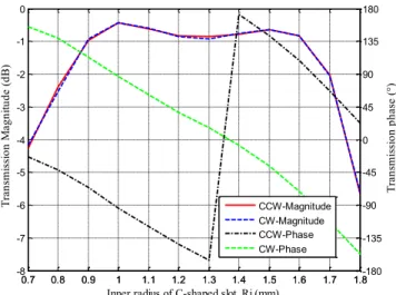
property corresponds to a 1-bit phase resolution, as demonstrated in previous papers, e.g. [11]. The transmission coefficients are plotted at 29.5 GHz in phase and magnitude in Fig. 2, as a function of the inner radius of the C-shaped slot; two cases are compared in this figure: CW (dotted line) and CCW (solid line) rotation. As expected, a 180-deg. phase shift is obtained between both configurations, while keeping transmission loss lower than 1 dB. In both cases, the inner radius varies between 0.9 mm and 1.6 mm. In conclusion, the incident and radiating fields are always orthogonal, and the transmission phase range covers 360° with quasi-linear and
parallel phase curves with respect to inner radius Ri as shown in
Fig. 3 for various frequencies. The performance of unit-cells under oblique incidence indicates a phase variation of about 30° and no significant change in magnitude for incidence angles up to 30° in both TE- and TM-modes (the results are not shown for brevity purpose).
Fig. 2. Variation of the transmission coefficients (in magnitude and phase at 29.5 GHz) of the MOUC with three-layer as a function of the inner radius Ri of
the C-shaped slot.
Fig. 3. Transmission phase of the MOUC with respect to the inner radius Ri of
the C-shaped slot for various frequencies. Solid lines refer to clock-wise model (Fig. 1a) and dashed lines refer to counter-clockwise model (Fig. 1b).
0.7 0.8 0.9 1 1.1 1.2 1.3 1.4 1.5 1.6 1.7 1.8 -8 -7 -6 -5 -4 -3 -2 -1 0 T ra ns m is si on M ag ni tu de (d B)
Inner radius of C-shaped slot, Ri (mm)
0.7 0.8 0.9 1 1.1 1.2 1.3 1.4 1.5 1.6 1.7 1.8-180 -135 -90 -45 0 45 90 135 180 T ra ns m is si on p ha se (°) CCW-Magnitude CW-Magnitude CCW-Phase CW-Phase 0.9 1 1.1 1.2 1.3 1.4 1.5 1.6 1.7 -540 -495 -450 -405 -360 -315 -270 -225 -180 -135 -90 -45 0
Inner radius of C-shaped slot, Ri (mm)
T ra ns m is si on p ha se (°) 27.5 GHz 28 GHz 29.5 GHz 31 GHz 31.5 GHz
III. METAL-ONLY TRANSMITARRAY ANTENNAS:DESIGNS AND EXPERIMENTS
Three 25-by-25 element MOTAs (MOTA#1, #2, and #3) with different pointing directions have been studied. They are illuminated by a standard 15-dBi gain pyramidal horn at 29.5 GHz. The array lattice (5 mm) is around half a wavelength at Ka-band. The focal length F is set to 135 mm in order to maximize the antenna gain at 29.5 GHz (F/D=1.08, where D= 125 mm denotes the length of the TA edge). The layouts have been determined using our in-house CAD tool based on array theory and phase-only synthesis, and validated in previous publications e.g. [2], [7], [11]. For brevity purposes, we provide only numerical results for the prototype pointing at broadside (MOTA#1), while our results are confirmed experimentally for both prototypes pointing in offset directions (MOTA#2 and #3). The simulation results have been obtained using the time domain solver of CST Microwave Suite, with an accuracy level set to –40 dB.
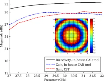
Fig. 4. Computed directivity and gain of MOTA#1. Inset: phase distribution across the radiating aperture at 29.5 GHz.
Fig. 5. Computed normalized co-polarization radiation patterns of MOTA#1 at 29.5 GHz in E- and H-planes (EP and HP).
The frequency response of MOTA#1 in directivity and gain is represented in Fig. 4. Their values computed at 29.5 GHz with our CAD tool reach 32 dBi and 29.9 dBi respectively (the
gain value computed with CST equals 29.3 dBi). The 3-dB bandwidth exceeds 15% around 29.5 GHz, and the calculated radiation and aperture efficiencies equal 62% and 51% respectively. Fig 5 shows a good agreement between the simulated and computed (our CAD tool) radiation patterns. The 3-dB gain bandwidth covers full range of up-link band. Moreover, thanks to the combination of two UC models with opposite polarizations, the XPD is extremely low (below -25 dB). The power budget, based on the array theory described in [2], is provided in Table II.
TABLEII
POWER BUDGET OF MOTA#1(POINTING AT BROADSIDE) AT 29.5GHZ. MOTA #1
Horn gain (dBi) 15.1
Directivity (dBi) 32 Spill-over loss (dB) 1.0 Illumination loss (dB) 0.4 Insertion loss (dB) 0.7 Gain (dBi) 29.9 Aperture efficiency 50.9%
Two 25×25-element prototypes (MOTA#2 and MOTA#3) have been fabricated to validate the proposed concepts for beam scanning. The metal layers made of brass plates have been etched by laser ablation (pulse duration 20 µs, λ = 1064 nm, 100 iterations, Fig. 6). Due to power limitations of the laser, thin brass sheets have been used (200-µm thick). The main fabrication parameters have been optimized to reach a fabrication accuracy of about ±50 µm over a large area (up to 25 cm × 18 cm).
Fig. 6. Prototyping by laser ablation at IETR.
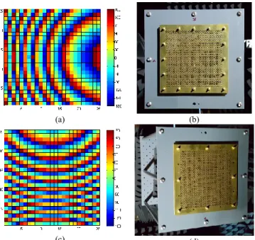
In practice, the metal layers of both MOTAs are separated using 3-mm thick foam spacer located around the TA edges. The alignment accuracy is around ±50 µm. The inner radius of the UC varies between 1.0 and 1.6 mm with a step of 0.1 mm. The focal length is kept fixed at 135 mm (F/D = 1.08). This leads to an oblique incident angle of about 25° at the edge centers and 32° at the corners. A 15-dBi standard gain horn (ATM 28-441-6) is used as feed source. The main beam directions of MOTA#2 and MOTA#3 point at 30° in H-plane and 50° in E-plane, respectively. The phase distribution and breadboards are represented in Fig. 7.
27 27.5 28 28.5 29 29.5 30 30.5 31 31.5 32 15 18 21 24 27 30 32 Frequency (GHz) M ag ni tu de (d Bi )
Directivity, In-house CAD tool Gain, In-house CAD tool Gain, CST -90 -75 -60 -45 -30 -15 0 15 30 45 60 75 90 -60 -50 -40 -30 -20 -10 0 theta(°) N orm al iz ed p at te rn (d B) CST, E-plane (EP) CST, H-plane (HP) In-house CAD tool, EP In-house CAD tool, HP
30 GHz (with a maximum deviation of 0.5 dB). A higher discrepancy (around 1 dB at 32 GHz for MOTA#3) is observed at higher frequencies (from 30 GHz to 32 GHz); this may come from possible fabrication inaccuracies, surface bending and misalignment between layers. The simulated 3-dB bandwidth of MOTA#2 spans from 28 GHz to 36 GHz (8 GHz) while it extends from 28.8 to 34.2 GHz (3.5 GHz) for MOTA#3. The difference between the measured gain curves of MOTA#2 and #3 (around 1.3 dB) is due to the different scan loss. Their measured gains reach 28.3 dBi and 26.6 dBi at 29.5 GHz, and their aperture efficiencies equal 36.5% and 20.9%, respectively; these values are slightly lower than those reported in [20] due to the different phase quantization strategy (the 1-bit unit-cell used here lead to higher quantization loss). The simulated and measured radiation patterns in co- and cross-polarizations are in very good agreement, as demonstrated by Figs. 9 and 10. The side-lobe and cross-polarization levels are kept below -16 dB and -22 dB respectively.
(a) (b)
(c) (d)
Fig. 7. (a,c) Phase distribution across the TA aperture at 29.5 GHz. (b, d) MOTA#2 and MOTA#3 prototypes.
IV. CONCLUSIONS
Metal-only unit-cells based on C-shaped slots have been proposed to design metal-only transmitarrays. We have shown that, by combining two unit-cells with opposite polarization directions, we can reach a 360-deg. phase range with low insertion loss and with only three metal layers. Two 25-by-25 element MOTAs have been fabricated by laser ablation and measured. The experimental results demonstrate very good performance, with a 3-dB gain bandwidth of 11 % around 29.5 GHz and high aperture efficiency for both prototypes. Compared to PCB counterparts, the proposed metal-only concepts are robust, easy to implement and lead to low cost solutions, which make them attractive for Satcom ground terminals.
This publication is supported by the European Union through the European Regional Development Fund (ERDF), and by Brittany Region, Ministry of Higher Education and Research, Rennes Métropole and Conseil Départemental 35, through the CPER Project SOPHIE / STIC & Ondes.
Fig. 8. Simulated and measured co-polarized gains of MOTA#2 and MOTA#3 at up-link Ka-band.
Fig. 9. Simulated and measured normalized co- and cross-polarization components of MOTA#2 in H-plane at 29.5 GHz.
Fig. 10. Simulated and measured normalized co- and cross-polarization components of MOTA#3 in E-plane at 29.5 GHz.
27 28 29 30 31 32 33 34 35 36 20 21 22 23 24 25 26 27 28 29 30 Frequency (GHz) G ai n (d Bi )
Gain, sim, MOTA #2 Gain, meas, MOTA #2 Gain, sim, MOTA #3 Gain, meas, MOTA #3
-80 -60 -40 -20 0 20 40 60 80 -40 -30 -20 -10 0 theta(°) N orm al iz ed ra di at io n pa tte rn (d B) Simulation, co-pol Measurement, co-pol Simulation, cross-pol Measurement, cross-pol -80 -60 -40 -20 0 20 40 60 80 -40 -30 -20 -10 0 theta(°) N orm al iz ed ra di at io n pa tte rn (d B) Simulation, co-pol Measurement, co-pol Simulation, cross-pol Measurement, cross-pol
REFERENCES
[1] C. G. M. Ryan, M. R. Chaharmir, J. Shaker, J. R. Bray, Y. M. M. Antar, and A. Ittipiboon, “A wideband transmitarray using dual-resonant double square rings,” IEEE Trans. Antennas Propag., vol. 58, no. 5, pp. 1486-1493, May 2010.
[2] H. Kaouach, L. Dussopt, J. Lanteri, T. Koleck, and R. Sauleau, “Wideband low-loss linear and circular polarization transmit-arrays in V-band,” IEEE Trans. Antennas and Propag., vol. 59, no. 7, pp. 2513-2523, Jul. 2011.
[3] Z.-W. Miao, Z.-C. Hao, G. Q. Luo, L. Gao, J. Wang, X. Wang, and W. Hong, “140 GHz high-gain LTCC-integrated transmit-array antenna using a wideband SIW aperture-coupling phase delay structure,” IEEE
Trans. Antennas Propag., vol. 66, no. 1, pp. 182-190, Jan. 2018.
[4] S. B. Yeap, X. Qing, and Z. N. Chen, “77-GHz dual-layer transmit-array for automotive radar applications,” IEEE Trans. Antennas Propag., vol. 63, no. 6, pp. 2833-2837, Jun. 2015.
[5] C. Jouanlanne, A. Clemente, M. Huchard, J. Keignart, C. Barbier, T. Le Nadan, and L. Petit, “Wideband linearly-polarized transmitarray antenna for 60 GHz backhauling,” IEEE Trans. Antennas Propag., vol. 65, no. 3, pp. 1440-1445, Mar. 2017.
[6] C.-C. Cheng, B. Lakshminarayanan, and A. Abbaspour-Tamijani, “A programmable lens-array antenna with monolithically integrated MEMS switches,” IEEE Trans. Microw. Theory Tech., vol. 57, no. 8, pp. 1874– 1884, Aug. 2009.
[7] L. Di Palma, A. Clemente, L. Dussopt, R. Sauleau, P. Potier, and P. Pouliguen, “Circularly-polarized reconfigurable transmitarray in Ka-band with beam scanning and polarization switching capabilities,” IEEE Trans.
Antennas Propag., vol. 65, no. 2, pp. 529-540, Feb. 2017.
[8] J. Y. Lau and S. V. Hum, “A planar reconfigurable aperture with lens and reflectarray modes of operation,” IEEE Trans. Microw. Theory Tech., vol. 58, no. 12, pp. 3547-3555, Dec. 2010.
[9] L. Di Palma, A. Clemente, L. Dussopt, R. Sauleau, P. Potier, and P. Pouliguen, “Circularly-polarized transmitarray with sequential rotation in Ka-band,” IEEE Trans. Antennas Propag., vol. 63, no. 11, pp. 5118-5124, Nov. 2015.
[10] E. Lima, S. Matos, J. Costa, C. Fernandes, and N. Fonseca, “Circular polarization wide-angle beam steering at Ka-band by in-plane translation of a plate lens antenna,” IEEE Trans. Antennas Propag., vol. 63, no. 12, pp. 5443-5455, Dec. 2015.
[11] K. Pham, R. Sauleau, E. Fourn, F. Diaby, A. Clemente, and L. Dussopt, “Dual-band transmitarrays with dual-linear polarization at Ka-band,”
IEEE Trans. Antennas Propag., vol. 65, no. 12, pp. 7009-7018, Dec.
2017.
[12] S. A. Matos, E. B. Lima, J. S. Silva, J. R. Costa, C. A. Fernandes, N. J. G. Fonseca, and J. R. Mosig, “High gain dual-band beam-steering transmit array for satcom terminals at Ka-Band,” IEEE Trans. Antennas Propag., vol. 65, no. 7, pp. 3528-3539, Jul. 2017.
[13] R. Pearson, “Next generation mobile SATCOM terminal antennas for a transformed world,” 5th European Conf. Antennas and Propagation,
Rome, Italy, Mar. 11-15, 2011.
[14] R. E. Hodges, N. Chahat, D. J. Hoppe, and J. D. Vacchione, “A deployable high-gain antenna bound for Mars: developing a new folded-panel reflectarray for the first cubesat mission to Mars,” IEEE Trans. Antennas
Propag., vol. 59, no. 2, pp. 39-49, Apr. 2017.
[15] A. Abdelrahman, A. Elsherbeni, and F. Yang, “Transmitarray antenna design using cross-slot elements with no dielectric substrate,” IEEE
Antennas Wireless Propag. Lett., vol. 13, 2014.
[16] G. Liu, H. Wang, J. Jiang, F. Xue, and M. Yi, “A high efficiency transmitarray antenna using double split rings slot elements,” IEEE
Antennas Wireless Propag. Lett., vol. 14, 2015.
[17] S. H. Ramazannia Tuloti, P. Rezaei, and F. Tavakkol Hamedani, “High-efficient wideband transmitarray antenna,” IEEE Antennas Wireless
Propag. Lett., vol. 17, no. 5, pp. 817-820, May 2018.
[18] M. O. Bagheri, H. R. Hassani, and B. Rahmati, “Dual-band, dual-polarised metallic slot transmitarray antenna,” IET Microw. Antennas
Propag., vol. 11, no. 13, pp. 402-409, 2017.
[19] R. Y. Wu, Y. B. Li, W. Wu, C. B. Shi, and T. J. Cui, “High-gain dual-band transmitarray,” IEEE Trans. Antennas Propag., vol. 65, no. 7, pp. 3481-3488, Jul 2017.
[20] B. Rahmati and H. Hassani, “High-efficient wideband slot transmitarray antenna,” IEEE Trans. Antennas Propag., vol. 63, no. 11, pp. 5149-5155, Nov. 2015.
[21] F. Yang, R. Deng, S. Xu, and M. Li, “Design and experiment of a near-zero-thickness high-gain transmit-reflect-array antenna using anisotropic metasurface,” IEEE Trans. Antennas Propag., vol. 66, no. 6, pp. 2853-2861, Jun 2018.
[22] A. H. Abdelrahman, A. Z. Elsherbeni, and F. Yang, “Transmission phase limit of multilayer frequency-selective surfaces for transmitarray designs,” IEEE Trans. Antennas Propag., vol. 62, no. 2, pp. 690-697, Feb. 2014.