HAL Id: cea-02075829
https://hal-cea.archives-ouvertes.fr/cea-02075829
Submitted on 21 Mar 2019HAL is a multi-disciplinary open access archive for the deposit and dissemination of sci-entific research documents, whether they are pub-lished or not. The documents may come from teaching and research institutions in France or abroad, or from public or private research centers.
L’archive ouverte pluridisciplinaire HAL, est destinée au dépôt et à la diffusion de documents scientifiques de niveau recherche, publiés ou non, émanant des établissements d’enseignement et de recherche français ou étrangers, des laboratoires publics ou privés.
Towards a portable smart spatial exploration system for
environment perception
S. Lesecq, O. Debicki, J. Foucault, L. Ouvry, M. Correvon, G. Dudnik, J.
Barrett, S. Rea, A. Mcgibney, F. Birot, et al.
To cite this version:
S. Lesecq, O. Debicki, J. Foucault, L. Ouvry, M. Correvon, et al.. Towards a portable smart spatial exploration system for environment perception. Smart System Integration 2018, Apr 2018, Dresden, Germany. �cea-02075829�
Towards a portable smart spatial exploration system for environment
perception
S. Lesecq, O. Debicki, J. Foucault, L. Ouvry, Univ. Grenoble Alpes, CEA, LETI F-38000 Grenoble, [email protected]
M. Correvon, G. Dudnik, CSEM SA, 2002 Neuchâtel, Switzerland J. Barrett, S. Rea, A. McGibney, Cork Institute of Technology, Ireland F. Birot, H. de Chaumont, L. Sevrin, GoSense, Lyon, France
R. Banach, J. Razavi, School of Computer Science, Univ. of Manchester, U.K. J. Herveg, N. Grandjean, Univ. of Namur, Belgium
C. Jackson, S. Buckley, SensL, Ireland
A. di Matteo, V. Di Palma, STMicroelectronics Srl, Naples, Italy
C. Ó’Murchú, A. Mathewson, R. O’Keeffe, Tyndall National Institute, Cork, Ireland
1 Introduction
The development of obstacle avoidance systems for autonomous vehicles is currently an active research topic. These systems combine multiple sensing technologies (e.g. LiDAR, radar, IR and visual) to detect different types of obstacles across the full range of possible lighting and weather conditions. Sensors data are fused with vehicle orientation (obtained for instance from an Inertial Measurement Unit and/or compass) and navigation subsystems. These systems are typically large, heavy, and not fully integrated in a unique device. They are power hungry and require powerful computational capabilities. They are indeed limited to high-end vehicles and robots.
2 INSPEX ambition
The objective of the H2020 INSPEX project is to make obstacle detection capabilities implemented in high-end vehicles available as a personal portable multi-sensors,
miniaturised, low power device. This device will be used for 3D real-time detection,
location and warning of obstacles under different environmental conditions, in indoor/outdoor environments, with static and mobile obstacles. Potential applications range from safer human navigation in reduced visibility conditions (e.g. for first responders and fire brigades), small robot/drone obstacle avoidance systems to navigation for the visually and mobility impaired people.
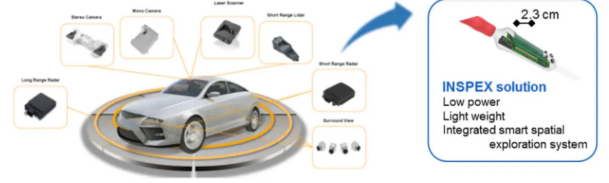
As primary demonstrator, the INSPEX device will be plugged on a white cane (see Fig. 1) for Visually Impaired and Blind (VIB) people to detect obstacle over the person height, provide audio feedback about harmful obstacles, improve their mobility confidence and reduce injuries, especially at waist and head levels [1]. The device will therefore offer a “safety cocoon” to its user. Electronic white canes already exist as products [2]. However, co-integration of several range sensor technologies will improve their detection capabilities. The partners brought to the project early prototypes of different range sensors, i.e. short and long range LiDAR (CSEM [5], Tyndall and SensL
[4]), RF UWB radar (CEA) [3], ultrasonic (STMicroelectronics), that will be optimised in the course of the project in order to meet the INSPEX system requirements.
Fig. 1: INSPEX ambition
3 Results of the 1st project year
The purpose of the 1st project year was to root the INSPEX system developments in
end-users’ real needs in order to develop a device that meets users’ expectation. 3.1 Methodology for the definition of INSPEX system requirements
Demonstration of the INSPEX system capabilities will be done through its integration on a regular white cane. Users’ needs have been collected via interviews of potential users of the INSPEX device. These needs have been gathered in six
Personas that are fictional characters, representing var-ious profiles of the targeted end-user community [7]. Being fictional, they can be deeply described and analysed without any concern about privacy. From these Personas,
functional and non-functional requirements have been defined together with their
priority of implementation in the three prototypes that are developed in the course of the INSPEX project. Then, system requirements have been derived for the VIB application. This methodology is summarised on Fig. 2.
3.2 System architecture design and firmware development
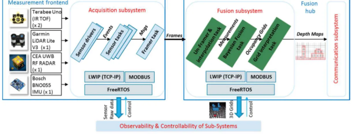
The architecture of the INSPEX system has been defined, having modularity as main concern in order to be easily adapted to other application domains. The system conceptual overview is given in Fig. 3 while the block diagram and interaction with the environment are given on Fig. 4. As can be seen, the so-called mobile detection device embeds range sensors, computational capabilities and communication with the smart gateway. The mobile detection device is split in two subsystems, namely, the measurement front-end and the fusion hub. This split provides also separation of concerns (sensors and acquisition, fusion and communication), and ease work in parallel of the different partners involved in the project.
Fig. 2: Methodology used to define the INSPEX system requirements for the VIB use-case
The software architecture has been designed in compliance with the system requirements, i.e. ensuring software reuse and modularity. Both software and hardware architects have work in strong cooperation. This early development of the software part will ease the final integration of the system, the software being “ready” at the time the hardware will be provided.
Fig. 3: INSPEX system conceptual overview (mobile
detection device) Fig. 3: system block diagram 3.3 Range sensor characterisation prior their integration in the INSPEX system Each range sensor (i.e. short and long range LiDAR, RF UWB radar, ultrasonic) brought in the project by partners have been characterised to evaluate its compliance with the requirements. From the characterisation results (see [4] for the UWB RF radar, [4] and [5] for the long and short range LiDARs), individual roadmaps have been derived to optimise both in size and power consumption these early sensor prototypes, prior their integration the final demonstrator.
3.4 Development of the first system prototype
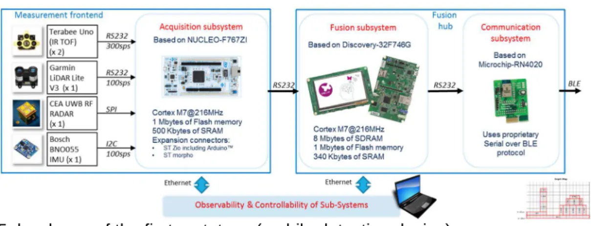
A first (non-integrated) prototype has been developed to showcase the system functionality and validate its consistency with a subset of the users’ needs. This first prototype ma inly focuses on the mobile detection device that provides information regarding obstacles in the user’s surroundings. It integrates different range sensors both provided by partners and taken off-the-shelf, together with a data fusion algorithm [6]. Its architecture (hardware and software) is fully compliant with the ones designed for the INSPEX device (see section 3.2 above). Fig. 4 shows an overview of the mobile detection device while Fig. 5 gives the hardware parts used. Note that FreeRTOS has been used in the acquisition and the fusion subsystems. In this way, the merge of both subsystems in a unique processer will be straightforward.
Fig. 5: hardware of the first prototype (mobile detection device)
4 Conclusion
The integrated prototype is currently under fabrication. Future steps include the optimisation of individual range sensors together with their co-integration in advanced integrated prototypes.
5 Acknowledgment
INSPEX has received funding from the EU's Horizon 2020 research and innovation programme under grant agreement No 73095, and from the Swiss Secretariat for Education,
Research and Innovation (SERI) under Grant 16.0136 730953.
6 References
[1] R. Manduchi, S. Kurniawan, “Mobility-Related Accidents Experienced by People with Visual Impairment”, Research and Practice in Visual Impairment and Blindness, 2011.
[2] Kun (Linda) Li, “Electronic Travel Aids for Blind Guidance – an Industry Landscape Study”, EECS, UC Berkeley, 2015.
[3] L. Ouvry, et al., “UWB Radar sensor characterization for obstacle detection with application to the smart white cane”, SSI 2018.
[4] R. O’Keeffe, et al., “Characterisation of Long Range LiDAR for Obstacle Detection with application to the Visually Impaired and Blind”, SSI 2018.
[5] G. Dudnik, et al., “Short Range LIDAR characterization for obstacle detection with application to a smart white cane”, SSI 2018.
[6] T. Rakotovao, et al., “Multi-Sensor Fusion of Occupancy Grids based on Integer Arithmetic,” ICRA 2016.
|7] S. Lesecq et al., “INSPEX: design and integration of a portable/wearable smart spatial exploration system”, DATE 2017.
[8] Deliverable D1.3 “Use cases and applications, preliminary version (VIB use-case)”, downloadable on http://www.inspex-ssi.eu/Pages/Deliverables/Deliverables.aspx