Design of a Four Rotor Unmanned Aerial Vehicle Capable of Sustaining Zero-roll and Zero-pitch Flight Using Vector
Thrusting
by
Danny Charles Hilton III
Submitted to the Department of Mechanical Engineering in Partial Fulfillment of the
Requirements for the Degree of Bachelor of Science
at the
MASSACHUSETTS INST'TE Massachusetts Institute of Technology OFTECHNOLOGY
June 2005 2 0 8
005
LIBRARIES
© 2005 Danny Charles Hilton III All rights reserved
The author hereby grants to MIT permission to reproduce and to
distribute publicly paper and electronic copies of this thesis document in whole or part.
Signature
of Author...
...
,
.~.-.-... .
.
Departmet"f Mechanical Engineering May 6, 2005Certified
by...
,...
;,
,---rEmesto
E. B aco
Prsr of
Mechanical
Engineering
Tle~s Supervisor
Accepted
by... ...
...
Ernest G. Cravalho Chairman, Undergraduate Thesis Committee© 2005 Danny Charles Hilton III All rights reserved
D)ESIGN OF A FOUR ROTOR UNMANNED AERIAL VEHICLE CAPABLE OF SUSTAINING ZERO-ROLL AND ZERO-PITCH
FLIGHT USING VECTOR THRUSTING
by
DANNY CHARLES HILTON III
Submitted to the Department of Mechanical Engineering on May 6, 2005 in partial fulfillment of the requirements for the Degree of Bachelor of Science in
Mechanical Engineering
ABSTRACT
In recent decades, remote controlled airplanes and helicopters equipped with video cameras have been used by the movie industry, photographers, and for surveillance. The military deploys these unmanned aerial vehicles (UAV's) to gather various types of reconnaissance. Recently, four-rotor helicopters have gained interest. A difficulty associated with attaching a camera to any type of helicopter is stabilization. Either the camera must be mounted on a motorized platform or the acquired data must be post-processed by a computer.
The objective of this thesis was to design and build a four-rotor UAV that can fly while remaining horizontal. The design presented here utilizes vector thrusting to achieve full maneuverability while not requiring tilting of the vehicle.
Thesis Supervisor: Ernesto E. Blanco Title: Professor of Mechanical Engineering
BIOGRAPHICAL SKETCH
Danny was born on the 20th of February in 1983 in San Diego, CA. At the age of two his family moved to Orange County and have since resided. At an early age, family members knew Danny was destined to be an inventor. For most of his childhood, Legos and Erector Set consumed much of his time. Danny's father soon introduced him to the world of electronics through various build-at-home kits and projects. The combination of electronics and mechanical systems has always interested Danny. By Junior High School, Danny had become quite familiar with remote controlled toys and often scavenged one vehicle to build one of his own creation. He was particularly interested in remote controlled aircraft and soon joined a local remote controlled glider club. In late High School, Danny began taking flying lessons to fulfill a fixed-wing private pilot license. Though he could not finish before matriculating at MIT, he hopes to resume his pursuit after graduation.
While attending MIT, Danny discovered a love for helicopters. This love and fascination with rotorcraft was an inspiration for this thesis. This thesis marks the culmination of a three semester journey of learning, hardship, and personal achievement. Entering into this project Danny knew it would be a challenge. Though possessing intermediate knowledge and skills in the field of electronics and engineering, working on this project independently pushed Danny to extend far beyond his knowledge-base and enabled him to learn so much more. While plans after graduation are uncertain, Danny hopes to enter the aerospace/defense industry. He dreams to one day purchase a kit and
ACKNOWLEDGEMENTS
This project would not have been possible without the help and support of my family, friends, and advisor. My parents, Dan and Sharon Hilton, provided sole financial support as well as life-long encouragement.
I would like to particularly thank Kenneth Schrock. Ken is an electrical engineering major and was my go-to man for all my electronics questions. Ken also spent countless hours helping debug the electronics system.
I would like to further thank my advisor, Professor Ernesto Blanco, for his guidance both with this project and in life. He provided insight and shared useful engineering experience. He also provided advice and encouragement as I begin my career as an engineer.
TABLE OF CONTENTS
A B S T R A C T ...3
BIOGRAPHICAL SKETCH ... 4
ACKNOWLEDGEMENTS ... 5
CHAPTER 1: Introduction ... 9
CHAPTER 2: Mechanical Design ... 12
2.1 UAV Platform ... 13
2.2 Vector Thrusting ... 15
CHAPTER 3: System Dynamics ... 17
CHAPTER 4: Electronics ... 25
CHAPTER 5: Conclusion ... 30
CHAPTER 6: Future Directions ... 31
REFERENCES ... 33
Appendix A: Vehiclel Specifications ... 34
Appendix B: Motor and Propeller Selection ... 35
Appendix C:: Photographs ... 38
Appendix D: Electrical Schematic and PCB Layout ... 39
LIST OF FIGURES
Figure 1. Different helicopter configurations...9
Figure 2. Complete SolidWorks assembly...12
Figure 3. Arrangement of the four-rotors ... 13
Figure 4. Servo actuation of thrust diverters...15
Figure 5. Arrangement and orientation of the thrust diverters ... 16
Figure 6. Two-dimensional dynamic model of the four-rotor UAV ... 17
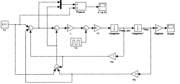
Figure 7. Simulink model for determining proper feedback coefficients ... 23
Figure 8. Vehicle and motor response to a disturbance ... 24
Figure 9. Two joystick radio transmitter layout...25
Figure 10. Pulse Width Modulation ... 27
Figure 11. Calculation of duty cycle for a PWM signal ... 28
LIST OF TABLES
Table 1. Motor Response to Attitude Change ... 14 Table 2. Servo Response for Flight Maneuvers ... 16 Table 3. Thrust comparison for two motor types...35
CHAPTER 1:
INTRODUCTION
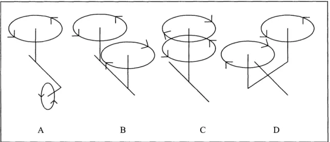
The single-rotor helicopter is the most widely used design for conventional rotorcraft. A single main rotor creates all the thrust required for flight. By moving the plane of the rotor, called the rotor disk, the helicopter can maneuver in all directions. However, the fuselage of the helicopter and the main rotor are mechanically coupled by the engine, and therefore, the fuselage will tend to rotate in the opposite direction of the rotor. Thus, the large torque produced by the main rotor must be counteracted by a tail rotor so that the fuselage will not rotate and can maintain a fixed heading. To avoid using a tail rotor, the helicopter may be designed with two main rotors that rotate in opposite directions. Figure
1 shows typical rotorcraft designs.
Figure 1. Different helicopter configurations. The traditional single-rotor (A) and the tandem rotor (B) helicopters are common today. Contra-rotating (C) and side-by-side (D) rotors are more rare. [1]
A B C D
)
Helicopters B, C, and D have an even number of counter rotating rotors that do not produce a net torque and therefore do not require a tail rotor.
With any rotorcraft, the direction of thrust must be changed in order to change the position of the vehicle. For conventional rotorcraft this means changing the angle of the main rotor disc(s). As the vehicle moves the fuselage will tilt in the direction of motion because the center of gravity is below the rotor disc(s). This is typically how helicopter flight is characterized and will be considered conventional throughout the remainder of this text. To move forward or backward, the helicopter's nose must be tilted downward or upward, respectively. To move sideways, the helicopter must be tilted sideways in the direction of desired motion. In general, helicopters that operate conventionally will move wherever the rotor disc(s) is tilted.
With single-rotor helicopters, a large amount of energy (i.e. fuel) is wasted because of the need of a tail rotor. Most of the noise of a helicopter is also produced by the tail rotor. There are several modem single-rotor helicopters that do not use tail rotors, but instead direct airflow to produce the same anti-torque effect. This type of anti-torque system is known as NOTAR. [2]
The objective of this project was to create a vehicle that could remain horizontal throughout flight, but achieve the same maneuverability as conventional rotorcraft. A four-rotor helicopter design was chosen for this task. A four-rotor design with counter rotating rotors eliminates the need for a tail rotor in addition to providing a stable
The main advantage of four-rotor vehicles is that they can perform any maneuver in any direction with equal performance. The vehicle has no front or back unless designated for piloting purposes. Therefore a four-rotor UAV is well suited for missions requiring operation in tight locations such as flying indoors and close to objects in which turning around is not possible or very dangerous. [3]
The most common and well suited applications for UAV's are carrying video equipment and other environmental measuring devices. Remote controlled helicopters equipped with video cameras are used frequently in the motion picture industry. They are also used to take still photographs for surveying purposes. The military uses UAV's to gather information about terrain and hostile activity, target acquisition, and limited weapons deployment. A four-rotor UAV that can maintain horizontal flight can offer a more suitable platform for surveillance equipment. Currently, to acquire a steady video or picture image, either the camera must be held in a fixed position or the data must be post-processed by a computer to stabilize it. Typically, the video camera is mounted on motorized gimbal that holds the camera still while the vehicle maneuvers. These platforms are very heavy and demand quick mechanical response. A four-rotor UAV that can maintain horizontal flight will not require a stabilizing camera mount.
CHAPTER 2:
MECHANICAL DESIGN
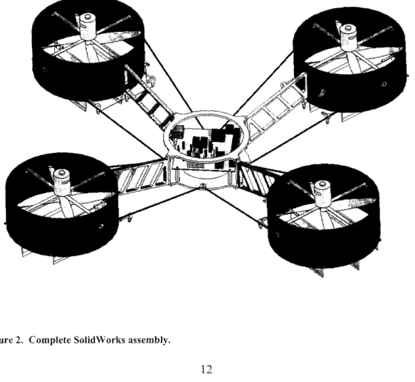
To meet the zero-roll, zero-pitch requirement, a four-rotor design was chosen that utilized vector thrusting to maneuver. Having four-rotors enables the vehicle to stabilize about its center of mass while maintaining a horizontal attitude. Vector thrusting allows the vehicle to move in any direction without the need to tilt as with conventional rotorcraft and other four-rotor UAV's. Figure 2 below shows the fully assembled vehicle.
0~'f
7/w,/
Figure 2. Complete SolidWorks assembly.
2.1 UA V Platform
A four rotor design was chosen because of its equal flight characteristics about its roll and pitch axes while maintaining no net torque on the vehicle. The typical four-rotor design was chosen consisting of four rotors symmetrically placed in a square pattern.
Figure 3. The four rotors are arranged in a square pattern and two rotor rotate clockwise and two rotate counterclockwise.
As Figure 3 shows, rotors 1 and 3 rotate clockwise and 2 and 4 rotate counter-clockwise.
Each rotor is shrouded by a thin, but stiff carbon fiber duct. This serves three purposes. First, it protects people and objects from being struck by the fast rotating rotors. Second, rotor efficiency is improved by channeling the airflow directly into the
rotors and straight down. Third, the ducts provide a mounting for the thrust diverting flaps and their servo actuators.
As a result of the motors and thrust diverters being placed a significant distance from the center pod a substantial bending moment is produced within the support strut. The small inertia of the support strut and the large bending moment create a swaying motion of the rotor pods giving rise to the vehicle's dominant mode of vibration. To counter this swaying motion support rods were added between the rotor pods and the center pod. The support rods are rigid members subjected to compression and tension. The main support strut carries all of the weight of the rotor pods, while the support rods carry the side-to-side load caused by swaying. Together, they create a rigid structure capable of supporting the weight of the entire rotor pod and resisting swaying motion.
The UAV is actively controlled to maintain horizontal stability. This is accomplished by changing the speed of each rotor accordingly. For example, if the UAV is tilting to the
left, the rotors on the left side will speed up to produce more thrust. In order for the UAV to hold a steady altitude, the net thrust should remain constant. Therefore, any positive adjustment made to one rotor should negatively affect the opposite rotor. The logic behind this control scheme is rather simple and is tabulated below.
Table 1. Motor Response to Attitude Change
Motor 1 Motor 2 Motor 3 Motor 4
Roll Left + - - + Roll Right - + + -Pitch Up - - + + Pitch Down + + - -Up + + + + Down .
2.2 Vector Thrusting
Movement using vector thrusting is accomplished by redirecting the outflow of air produced by the rotors in a coordinated fashion. In an ideal application, each of the four ducted rotors would be able to pivot independently in two directions. For simplicity, the vehicle designed in this project uses flaps, thrust diverters, installed below the rotors to divert the air keeping the rotors mounted in a fixed position. For further simplicity, the flaps under each rotor are given only one degree of freedom. This not only lowers the mechanical complexity but also the control algorithms. The thrust diverters are aligned radially outward relative to the vehicle's center. The thrust diverters are controlled by a servo actuator and tied together by linkages. See Figure 4 for detail. By moving the four sets of thrust diverters in a specific pattern, a net motion in any direction can be achieved.
Figure 4. Servo actuation of thrust diverters. The three individual flaps are linked together and
move parallel to each other at all times.
Figure 5 below illustrates the orientation of the thrust diverters as well as their local coordinate system. If the thrust diverters move in the positive direction, air is directed in the positive direction and the net force on the vehicle is in the negative direction.
q-+ 2 I 3
_
+
Figure 5. Arrangement and orientation of the thrust diverters. The thrust diverters are aligned
radially relative to the vehicle. The plus and minus sign represent the local motion of the diverters.
Table 2 below shows the control scheme for moving the thrust diverters to produce a net motion. These movements may be combined to produce any desired flight path.
Table 2. Servo Response for Flight Maneuvers
Servo 1 Servo 2 Servo 3 Servo 4
Forward
-
+ + Backward + --
+
Left + + --Right-
- + + Rotate Right - - - -Rotate Left + + + + -4CHAPTER 3:
SYSTEM DYNAMICS
Most of the analysis can be done in two dimensions since the vehicle is symmetric about its yaw axis and that the rolling and pitching behaviors are the same. The system will be modeled as shown in the following figure containing a central mass acted upon by the thrust from two rotors and half the vehicle's weight.
FL
FR
0
Center of Mass
I
Mg
2Figure
6. Two-dimensional dynamic model of the four-rotor UAV.
Figure 6. Two-dimensional dynamic model of the four-rotor UAV.
The vehicle's desired equilibrium position is horizontal. The feedback control system will alter the thrust produced by each rotor in order to maintain equilibrium during flight. Typically, a vehicle is designed such that it naturally tends to return to equilibrium. This will help give the control system a biased state and ensure that in the case of control
system failure the device will not become unstable. In general, for a vehicle to be stable, that is, it tends to equilibrium after a disturbance; the center of mass must lie below the center of support. Under this condition, if the vehicle is tilted the center of support is no longer aligned vertically with the center of mass and a resulting restoring moment is produced. It's this restoring moment that tends to push the vehicle back into equilibrium.
This principle is fundamental to the stability of boats, hot air balloons, and submarines. However, this principle only applies to vehicles in which the forces acting upon it are always vertical. The fixed rotors of a UAV rotate with the vehicle about its center of mass thereby creating no restoring moment unless the thrusts are unequal. Therefore, a fixed-rotor JAV is inherently unstable without the aid of control. This further asserts that it is irrelevant, in practical terms, where the center of mass lie along the vertical axis of symmetry. These assertions can be further shown by analyzing the system dynamics.
For any rigid-body it holds that a net torque will result in angular rotation as described by
'r:I 0,
(1)
where r is an individual torque, I is the mass moment of inertia, and 0 is the angular displacement.
Inserting the appropriate values into Equation yields
TD -FLL+FRL=I , (2)
where TD is a disturbance torque, FL is the upward force created by the left rotor, FR is the upward force created by the right rotor, and L is the separation distance between the rotor and the vertical axis of symmetry. Taking the Laplace Transform of Equation 2 results in
Is20(s)=
TD(s)+[FR(s)-FL(s)1L
(3)
and rearranging terms yields
H(s)- (s) 1 (4)
TD(s) Is2
Without active control the UAV is inherently unstable. If disturbed while in flight, the UAV will not return to a horizontal equilibrium. The plot below illustrates this point.
Impulse Response without Feedback Control
250 . . . 200 ,? 150 ~- 100 E so0 0 0.1 0.2 0.3 0.4 0.5 0.6 0.7 0.8 0.9 1 Time (sec)
Adding proportional feedback control yields the following transfer function,
H(s)= 0)
I
T
D(s) - Is' + 2LKp
50 40 30 20 10 0 -10 -20 -30 -40 -50Impulse Response with Proportional Feedback Control
0) 02 0.4 0.6 0.8 1 12 14 16 1.8B Time (sec) (5) U, a-E
With proportional feedback the vehicle oscillates indefinitely because it is an undamped system. Derivative feedback will add damping to the response:
H(s) = () 1
TD(s) Is2
+ 2LKos + 2LKP
Impulse Response with Proportional and Derivative Feedback Control
02
04
06
0.8
1
Time (sec)
12
14
16
18
(6)
When designing the feedback system many issues had to be addressed to maintain feasibility of both the mechanics and electronics. The control system was designed by analyzing the impulse and step responses. The impulse response is analogous to bumping the UAV during flight. The impulse response will show how the control system responds to disturbances while actively maintaining balance. The analytical model created above
4 C I Z, 1 0 AD P CD
10
Q.) 4-4) 4) E<
n 0was analyzed using MatLab to establish approximate control parameters. The total mass and the moment of inertia were calculated by the SolidWorks assembly. The control parameters were then adjusted on the real vehicle to obtain the desired response characteristics. The maximum amplitude of oscillation, the settling time, and the maximum thrusting force required were critical specifications that were either limited by the vehicle or the digital electronics. Therefore the feedback control parameters were chosen such that the response met the specifications with reasonable tolerance. The most significant limitations were set by the electronics. The tilt sensors have a given sampling rate and the microprocessor updated each motor's rpm at a given refresh rate. Therefore the settling time must be long enough for the system to measure an adequate number of data points while not being too long such that the vehicle is never reaches equilibrium. The motor speed is discretized by the microprocessor and therefore had a set number of values (resolution). The feedback parameters could not be too high such that the required motor value exceeded its maximum. It was also desired that the vehicle not rotate more than 10 or 15 degrees in response to a 1 N'm moment. Using Matlab and Simulink the impulse response was studied while changing feedback parameters until an acceptable response was achieved. These parameters were then used in the microprocessor control program.
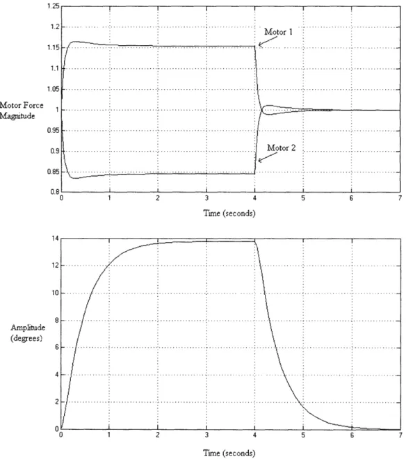
Figure 7 and Figure 8 show the Simulink model and the resulting system responses to a long impulse. The disturbance impulse was held high to allow for the vehicle to stabilize and then it was removed to show how the motor respond to such a disturbance.
1.25 1.2 1.15 1.1 1.05 Motor Force 1 Magnitude 0.95 0.9 0.85 0.8 Amplitude (degrees) 2 3 4 5 6 Time (seconds) Time (seconds)
Figure 8. Motor response (top) to an impulse. The rotation of the vehicle is shown in the lower plot.
CHAPTER 4: ELECTRONICS
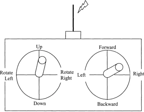
The entire system can be broken in to three subsystems: the peripheral system, the processing and control system, and the actuator system. A handful of sensors make up the peripheral system that is responsible for receiving flight instructions from the ground and detecting the attitude, heading, and altitude of the vehicle. Communication between the operator on the ground and the airborne vehicle is accomplished via a typical hobby 4-channel, joystick style transmitter and receiver pair operating in the 72 MHz radio frequency (RF). The operator may control the altitude, the heading, and the flight path from the two-joystick transmitter depicted in Figure 9 below.
Up Forward
Rotate Left
Down Backward
Right
The attitude, or roll and pitch, is measured by a Memsic 2125 dual-axis accelerometer configured to detect tilt about both axes. The heading, or yaw, is measured by a Devantech CMPS0 1 compass module.
The Basic Stamp 2p microcontroller (BS2p) manufactured by Parallax, Inc. [3] was chosen to handle all the data processing and control logic. The BS2p was available in a stand alone assembled 24-pin DIP package or as individual OEM components allowing integration into custom systems. The latter was chosen to save cost and ease implementation into the vehicle's control circuitry. The BS2p is programmed in Basic and has 16 I/O pins, a clock frequency of 20 MHz, and can process up to 12,000 instructions per second. Parallax, Inc. manufactures many configurations of the Basic Stamp, but the BS2p was chosen for its higher speed and larger memory. During the brainstorming stage, other microcontrollers were considered, such as Microchip's PIC microcontrollers, which are programmed in C. Although the ratio of the number of available types of PICs to Basic Stamps are ten fold and the Basic Stamps' capabilities are limited by its Basic programming, the Basic Stamp was chosen because of its built-in functions that already catered to this project and thus would require much less programming. In addition, Parallax, Inc. also sold add-on motor and servo control modules that are easily interfaced with the Basic Stamps.
The four thrust producing rotors and the four servo actuators that move the thrust diverters make up the actuator system. Both the rotor motors and the servos are direct current (DC) permanent magnet motors. However, the rotor motors rotate continuously while the servos are limited to a range of 180°. Though they both operate differently,
they can both be controlled by Pulse Width Modulation (PWM). PWM is the most effective method to vary the speed of a motor in continuous operation or its position in the case of the servo. In PWM, a series of rectangular pulses of full amplitude flow through the motor, or any load in general, so that the average voltage is varied instead of the total voltage. There are multiple ways to implement PWM, but the two most common are fixed-pulse and fixed frequency. Figure 10 shows how changing the duty cycle, the ratio of how long the pulse is high to low, effectively changes the average voltage.
Figure 10. Pulse Width Modulation is essentially a digital signal, either on or off, but the average voltage can be varied by changing the duty cycle.
Pulse Width Modulation is the most favorable method to control motors for most applications and is especially well suited for applications in which a microcontroller is
I , -20%
JEIIEJ~~~~~~~~~~~~~~~~~~~~~~~~~~~~~~
I I~~~~~~~~~~~~~~~~~~~~~~~ 140%
0
1LL
1 1 1> 1~~~~~~~~~~~~~~ I I I 80%, 0~ ...~~
..used. Since PWM is essentially a digital signal, either on or off, the microcontroller needs to only control the amount of time the signal is on and off.
The accelerometer, compass, and radio receiver encode their information and output it as PWM. As described above, the frequency remains constant while the duty cycle is varied according to the value being measured by the sensor. The accelerometer for example, will output a 50% duty cycle when it is not tilted. As it is tilted one way or the other the duty cycle will decrease or increase accordingly. For the microprocessor to understand this information, the analog PWM must be decoded into the digital equivalent. There are two practical methods in which the PWM can be converted into a digital value. The first method is to do this within the microprocessor. The duty cycle is the ratio of the on-time to the total period (the on-time plus the off-time). The on-time is the amount of time the signal is at the voltage corresponding to high or a digital 1. The off-time is the amount of time the signal is low (usually ground) or a digital 0. Therefore, all the microprocessor needs to do is measure the amount of time the signal is high and then low. Figure 11 demonstrates this method.
Ton
5'V
DutyCycle To0V
J
ToffThe other method to decode PWM is to first low-pass filter the signal which converts it from a square wave signal to a relatively flat analog voltage of which its value is directly related to its duty cycle. An Analog-to-Digital Converter is then used to measure the analog voltage and convert it into a discrete number that the microprocessor can interpret.
Both methods were tried, but the first method was ultimately used because the BS2p has a built in pulse width measuring function.
Figure 12 below shows the overall system block diagram.
Motr 1
Digital Copa
CHAPTER 5:
CONCLUSION
This project set out to design a four-rotor UAV that operated differently from conventional vehicles. The vehicle presented here is a test of concept. Over the past year and a half much was accomplished. A four-rotor UAV was developed that uses flaps to divert thrust in order to maneuver without requiring tilting the vehicle. The vehicle was made out of carbon fiber laminate, steel, and ABS plastic. The vehicle is lightweight, has minimal structural complexity, but is still robust and well balanced. In the end, a complete flight was not accomplished. All systems were demonstrated to work properly, but there was insufficient thrust to sustain full flight. The vehicle did, however, hover at approximately 2-3 inches while in ground effect. With minor improvements to the propulsion system, it is expected that the vehicle would perform as designed at a reasonable altitude out of ground effect.
This project was a large undertaking for one engineer given no institutional or government funding. The entire structural and electrical design was accomplished by myself with limited advice and aid from others.
On a personal level, I feel very proud of what I have accomplished. Even though in the end a fll flight was not achieved, I am still very satisfied and confident with the overall design of the vehicle and its basic concepts. This project encompassed many fields of engineering and the experience and knowledge I have acquired I will carry with me further into my career.
CHAPTER 6:
FUTURE DIRECTIONS
To achieve full flight out of ground effect the thrust problem must addressed. Providing adequate thrust is the only area that requires upgrading. Brushless motors should replace the current brushed motors. Brushless motors are more efficient and typically much lighter than their brushed counterparts. Therefore more powerful brushless motors can be used while conserving the current weight of the UAV. Furthermore, slightly larger pitched propellers could be used by the added power of the brushless motors. It is also much easier to control and measure the speed of brushless motors and this would add an additional control parameter to the vehicle that it currently does not have.
Another possible solution to the thrust problem is to use miniature internal combustion glow engines made for hobby applications. These engines have a very high power to weight ratio and could be easily implemented into the current design. Using glow engines would eliminate the need for large capacity and heavy batteries and carrying fuel would be much lighter because it has a higher power density than batteries.
Currently, altitude is not controlled by the device because it is not equipped with an altitude sensor. The user must adjust the rotor speed to maintain a constant altitude. To measure altitude, infrared and ultrasonic sensors would be an inexpensive method. These sensors work by transmitting a signal and measuring the time it takes to bounce back. These sensors, however, do not work very well over long distances. Thus, these sensors
would be used for close to ground flight in which accuracy was important. For higher altitudes in which accuracy is not as critical, a pressure transducer could be used.
To drastically improve attitude assessment during flight, the accelerometers could be replaced by an Inertial Measurement Unit (IMU). This would enable more accurate stability control. An IMU would further aid in reporting back to ground stations accurate vehicle dynamics and how well the device is responding to the environment.
The main cause of the sluggish response of the control system is due to the fact that the radio system uses PWM with a long period (-50ms). A significant amount of time is required to measure the four channels and calculate the proper control response. The measured values also fluctuate due to an intrinsic error caused by the PWM pulses not being perfectly rectangular. To improve the speed and accuracy of this acquisition, a digital remote control system should be utilized. These systems are commonly used in high performnance remote controlled aircraft and helicopter applications, but are very expensive
REFERENCES
[1] Padfield, R. Randall. Learning to Fly Helicopters. McGraw-Hill, 1992 [2]
1J.S.
Department of Transportation, Federal Aviation Administration.Rotorcraft Flying Handbook. Aviation Supplies & Academics, 2000
[3] Nice, Eryk B. "Design of a Four Rotor Hovering Vehicle," 2004
http://dspace.library.cornell.edu/bitstream/1 813/93/2/Designof4RotHoverVehi
cle.pdf
[4] Parallax, Inc: Manufacturer of Basic Stamp Microcontrollers http://www.parallax.com
[5] Diversity Model Aircraft, Electric Motor Calculator
APPENDIX A: VEHICLEL SPECIFICATIONS
24
APPENDIX B: MOTOR SELECTION
Two types of motors were purchased and their performances of driving different types of propellers were compared. The thrust data was calculated using Diversity Model Aircraft's Electric Motor Calculator [5], a software program specifically designed for evaluating electric hobby motors fitted with propellers. Using the software the optimal propeller pitch was selected for each motor. The Mabuchi RS-390PH was fitted with a GWS 7"x3.5" propeller and the Graupner Speed 700 Turbo was fitted with an APC 7"x9" prope ller. The following table and figures shows how the number of motors affects the total weight and thrust. It further shows the percent power required to hover. The Graupner motor was selected for the final vehicle.
Motor Number Total Vehicle Total Net Upward Thrust/Weight % Throttle
Type of Motors Weight Thrust Force Ratio @ Hover
1 38.82 17 -21.82 0.44 228.4 2 41.64 34 -7.64 0.82 122.5 3 44.46 51 6.54 1.15 87.2 RS-380PH 4 47.28 68 20.72 1.44 69.5 5 50.1 85 34.9 1.70 58.9 6 52.92 102 49.08 1.93 51.9 7 55.74 119 63.26 2.13 46.8 1 47.29 42 -5.29 0.89 112.6 2 58.58 84 25.42 1.43 69.7 Graupne 3 69.87 126 56.13 1.80 55.5 Graupner -700 -_4 81.16 168 86.84 2.07 48.3 5 92.45 210 117.55 2.27 44.0 6 103.74 252 148.26 2.43 41.2 7 115.03 294 178.97 2.56 39.1
Thrust-to-Weight Ratio
3.00
'
2.50 1.50 - - - _ _ _ _ _ _ _ __ _ _ _ _ _ _ _ - _ _ _ _ __-/ -4-RS-380PH1 -f--,-- Graupner 700 1.00 0.50 0.00 0 1 2 3 4 5 6 7 8 Number of Motors % Power @ Hover ZtU.U -200.0 150.0 100.0 50.0 0.0 -4-PS-380PH -U-Graupner 700 0 2 4 Number of Motors 5 8 3 INet Upward Force vs. Motor Number -5 0 . . . -. - - - - .- - - . . . Number of Motors 37 zUU 150 0 ° 100 0 U. *0S 0.L _ 50 z 0 8
Below is a stand that was designed and built for testing purposed. The stand allows the UAV to pivot in all directions and rotate horizontally.
APPENDIX D: ELECTRICAL SCHEMATIC AND PCB LAYOUT
*rtKI
ir , = i25 I-8-1I
I Ii
'i, sAPPENDIX E: MICROCONTROLLER CODE LISTING
File ... Hover.BSP
Purpose.... this program uses the throttle input plus the gryos to hover. Author ... Danny Hilton
E-mail ... dhilton~mit.edu Started.... 3-8-05
{$STAMP BS2p}
' ---[ I/O Definitions
]---Serial_pin PIN 0 Throttle pin PIN 6
Rollpin
Pitch_pin
PIN 1
PIN 2
'Serial I/O to PWMPal & Servo Controller 'Receiver Channel 4, throttle
'Roll input from gyro 'Pitch input from gyro
---[ Constants ]---Serialbaud CON 45 'using 38.4 kbps transmission
Motorstatus
CON
Motor_1 Motor_2 Motor_3 Motor 4 CON CON CON CON %11110000 1 2 3 4 PWM_period CON 100' motor control status, software control, all channels enabled
' motor channel 1, left front ' motor channel 2, right front ' motor channel 3, right rear ' motor channel 4, left rear
' sets PWM frequency 1/(10*25us) = 4kHz Zeroed_:roll
Zeroedpitch
Kp Kd dt CON CON CON CON CON 50 50 2 2 2' roll value for horizontal ' pitch value for horizontal 'proportional gain
'derivative gain
time between gyro reading, used in derivative ---[ Variables
---' speed, 0% to 100%
'PWM timing for motor 1 'PWM timing for motor 2 'PWM timing for motor 3 'PWM timing for motor 4
roll VAR Word
lastroll VAR Word
pitch VAR Word
last_pitch VAR Word roll_adj VAR Byte pitch_adcj VAR Byte throttle VAR Word
actual pulse in from Memsic 2125
' actual pulse in from Memsic 2125
' amount added or subracted during control ' amount added or subracted during control 'throttle value
---[ Initialization ]---DIRS = %0000000001000110
MotorSetup:
SEROUT Serialpin, Serial_baud, ["!PWMSS", Motorstatus]
lastroll = Zeroed roll last_pitch = Zeroed_pitch
--- [ Program Code ]---Main:
GOSUB3 Read receiver ' gets throttle value IF NOT (throttle <= 100) THEN 'makes sure transmitter is turned on
GOSUB Notransmitter
speed_1 speed_2 speed_3 speed_4 timing_1 timing_2 timing_3 timing_4 VAR VAR VAR VAR VAR VAR VAR VAR Byte Byte Byte Byte Word Word Word WordENDIF
GOSUB Readgyro
' gets attituderoll_adj = (ABS(zeroed roll - roll) * Kp) - (ABS(lastroll - roll) * dt * Kd) ' only words can be negative, so we have to use abs( and if...then...else
pitchadj = (ABS(zeroed_pitch - pitch) * Kp) - (ABS(last_pitch - pitch) * dt * Kd) IF (zeroed_roll > roll) THEN
speed_1 = throttle + rolladj speed_4 = throttle + roll_adj speed_2 = throttle - rolladj speed_3 = throttle - rolladj
ELSEIF (zeroed_roll < roll) THEN speed_1 = throttle - roll adj speed 4 = throttle - roll adj speed 2 = throttle + roll adj speed_3 = throttle + roll adj ELSE speed._ = throttle speed 2 = throttle speed 3 = throttle speed 4 = throttle ENDIF
IF (zeroed_pitch < pitch) THEN speed 3 = speed 3 + pitch adj speed 4 = speed_4 + pitchadj speed = speed_ 1 - pitchadj speed 2 = speed_2 - pitchadj
ELSEI] (zeroed_pitch > pitch) THEN speed 3 = speed_3 - pitch_adj speed 4 = speed_4 - pitchadj
speed 1= speed-1 + pitchadj
speed 2 = speed-2 + pitchadj ELSE speed._ 1 = speed_1 speed 2 = speed_2 speed 3 = speed_3 speed 4 = speed 4 ENDIF
'means device is rolling left
means device is rolling right
means device is not rolling
' means device is pitching up
' means device is pitching down
IF (speed_1 > 200) IF (speed_2 > 200) IF (speed_3 > 200) IF (speed_4 > 200) THEN THEN THEN THEN speed_1 speed 2 speed_3 speed_4 = 0: ENDIF = 0: ENDIF = 0: ENDIF = 0: ENDIF IF (speed_1 > IF (speed_2 > IF (speed_3 > IF (speed_4 > 100 100 100 100 AND AND AND AND speed_1 <= 200) speed_2 <= 200) speed_3 <= 200) speed_4 <= 200) THEN THEN THEN THEN speed_1 speed_2 speed_3 speed_4 = 100: ENDIF = 100: ENDIF = 100: ENDIF = 100: ENDIF IF (throttle = 0) IF (throttle = 0) IF (throttle = 0) IF (throttle = 0) THEN THEN THEN THEN speed_1 speed_2 speed_3 speed_4 = 0: ENDIF = 0: ENDIF = 0: ENDIF = 0: ENDIF GOSUB Update_motors PAUSE 500 lastroll = roll last_pitch = pitch GOTO main END [ Subroutines
]---Readgyro:
'reads outputs from gyroPULSIN Roll_pin, 1, roll roll = roll / 32 - 150
PULSIN Pitch_pin, 1, pitch pitch = pitch / 32 - 150
'measure roll pulsewidth ' center the value to 50
' measure pitch pulsewidth ' center the value to 50 RETURN
Read receiver: 'measures pulsewidths from R/C receiver PULSIN Throttle_pin, 1, throttle
throttle = (throttle-1485)/10
' measure throttle pulsewidth ' convert it to range of 0-100
RETURN
Update motors: ' sends motor values to PWMPal timing l.BYTE1 = speed_1 'on time for motor 1
timing 1.BYTE0 = PWMperiod-speedl ' off time for motor 1 timing 2.BYTE1 = speed_2
timing 2.BYTE0 = PWMperiod-speed_2 timing 3.BYTE1 = speed_3
timing_ 3_3.BYTE = PWMperiod-speed_3
timing 4.BYTE1 = speed_4
timing 4.BYTE0 = PWM_period-speed_4
SEROUT Serial_pin, Serial_baud, ["!PWMM", %0000, timing_l .BYTE0, %0000]
SEROUJT Serial_pin, Serial_baud, ["!PWMM", %0000, timing_2.BYTE0, %0000]
SEROUT Serialpin, Serial_baud, ["!PWMM", %0000, timing_3.BYTE0, %0000]
SEROUT Serial_pin, Serial_baud, ["!PWMM", %0000, timing_4.BYTE0, %0000]
(48 + Motorl1), timing_l.BYTE1,
(48 + Motor_2), timing_2.BYTE1, (48 + Motor_3), timing_3.BYTE1, (48 + Motor_4), timing_4.BYTE1,
DEBUG CLS, "motor 1 ", DEC speed 1, "motor 2 ", DEC speed_2, "motor 3 ", DEC speed_3, "motor 4 ", DEC speed_4,CR
DEBUG "Roll ", DEC roll, "Pitch ", DEC pitch RETURN
Notransmitter:
'waits here until transmitter is turned on DO UNTIL (throttle <= 100)GOSUB Readreceiver
DEBUG CLS, "Please turn on transmitter on" LOOP
File... Flaps-only.BSP
Purpose .... this program uses the 4-channels to move the flaps. Author ... Danny Hilton
E-mail ... dhilton~mit.edu Started .... 5-2-05 {$STAMP BS2p} {$PBASIC 2.5}
---[ I/O Definitions
]---Serial_pin PIN 0 FwdBkwd_pin PIN 4 SidetoSide_pin PIN 5 Rotatepin PIN 7'Serial I/O to Servo Controller
'Receiver Channel 1, forward and backward 'Receiver Channel 2, side to side
'Receiver Channel 4, rotate
---[ Constants ]---Serialbaud CON 1021 '45
buff
'using 38.4 kbps transmission VAR Byte(3) Servo_1 Servo_2 Servo_3 Servo_4 C1 C2 C3 C4 CON CON CON CON CON CON CON CONflapbias
3 4 2 1 50 50 50 50 CON 5' servo channel 3, left front ' servo channel 4, right front ' servo channel 2, right rear ' servo channel 1, left rear ' center position for servo 1 ' center position for servo 2 ' center position for servo 3 ' center position for servo 4
'biases each flap to correct for net torque
---
---
--- -
--- [ Variables ]
---fwdbkwd VAR Word
sidetoside VAR Word
yaw VAR Word
p_1 VAR Word p_2 VAR Word p_3 VAR Word p_4 VAR Word ---[ Initialization ]---DIRS = %00000000101 10000 SetBaud:
'DEBUG "Setting Baudrate", CR
'SEROUT Serial_pin, 1021+$8000, ["!SCSBR", 1, CR] 'SERIN Serial_pin, Serial_baud, 500, SetBaud, [STR buff\3]
'DEBUG "Baud Reply: ", buff(0), buff(1), DEC1 buff(2), CR ---[ Program Code ]--- ---Main:
GOSUB Read_receiver 'gets throttle value p_1 =
C(1
+ fwdbkwd + sidetoside + yaw - 150 p2 =C('2
- fwdbkwd + sidetoside + yaw - 50 p_3 = ('3 - fwdbkwd - sidetoside + yaw + 50 p_4 = C4 + fwdbkwd - sidetoside + yaw - 50 GOSUB Update_servos' DEBUG CLS, "Servo 1 = ", DEC p_1," Servo 2 =",DEC p_2," Servo 3 = " DEC p_3," Servo 4 = ", DEC p_4, CR
END
---[ Subroutines
]---' measures pulsewidths from R/C receiver PULSIN FwdBkwd_pin, 1, fwdbkwd
fwdbkwd = (fwdbkwd-1415)/10 and hard limit it to that range
IF (fwdbkwd >= 100 AND fwdbkwd <= 3000) THEN IF (fwdbkwd > 3000) THEN fwdbkwd = 0
' convert it to range of 0-100 fwdbkwd = 100
PULSIN SidetoSide_pin, 1, sidetoside sidetoside = (sidetoside- 1365)/ 10
IF (sidetoside >= 100 AND sidetoside <= 3000) THEN sidetoside = 100 IF (sidetoside > 3000) THEN sidetoside = 0
PULSIN Rotatepin, 1, yaw yaw = (yaw-1420)/10
IF (yaw >= 100 AND yaw <= 3000) THEN yaw = 100 IF (yaw > 3000) THEN yaw = 0
RETURN Update servos: p_1 = (p_1 * 7) + 350 exceed 300 or 1100 IF(p_l >= 1150) THI IF (p_1 <= 350) THEI
' we want center to be about 700 in servo units and not
ENp_1 = 1150 N4p_l = 300
p_2 =(p_2 * 7)+350
IF(p_2 >= 1150) THEN p2 = 1150 IF(p_2 <= 350) THEN p_2 = 350 p_3 = (p_3 * 7) + 350IF(p_3 >=50)THENp= THEN p_3 = 11501150) IF (p_3 <= 350) THEN p_3 = 350 p_4 = (p_4 * 7) + 350
IF(p4 >= 1150)THENp_4= 1150
IF (p4 <= 350) THEN p_4 = 350
SEROUJT Serial_pin, Serial_baud+$8000,[" !SC", Servo_1, servo_ramp,
p_.LOWBYTE, p_l .HIGHBYTE, CR]
SEROUJT Serial_pin, Serial_baud+$8000,["!SC", Servo_2, servoramp, p_2.LOWBYTE, p_2.HIGHBYTE, CR]
SEROUJT Serial_pin, Serial_baud+$8000,["!SC", Servo_3, servoramp, p_3.LOWBYTE, p_3.HIGHBYTE, CR]
SEROUJT Serial_pin, Serial_baud+$8000,["!SC", Servo_4, servoramp, p_4.LOWBYTE, p_4.HIGHBYTE, CR]
File ... 4 Motors - Throttle.BS2
Purpose.... this program uses the throttle input to power up all 4 motors. Author ... Danny Hilton
E-mail ... dhilton~mit.edu Started.... 5-04-05 ' {$STAMP BS2} ' {$PBASIC 2.5 } --- [ I/O Definitions ] ---Serialpin PIN 0
Throttle pin PIN 1
'Serial I/O to PWMPal & Servo Controller 'Receiver Channel 4, throttle
--- [ Constants ]---Serialbaud CON 6 ' using 38.4 kbps transmission
Motorstatus
CON
channels enabled
%11110000 ' motor control status, software control, all
' motor channel 1, left front ' motor channel 2, right front ' motor channel 3, right rear ' motor channel 4, left rear
PWMperiod CON 100 ' sets PWM frequency 1/(10*25us) = 4kHz
---[ Variables
]---speed VAR Byte
timing VAR Word
throttle VAR Word
'speed, 0% to 100% 'PWM timing Motor_ 1 Motor 2 Motor-2 Motor_4 CON CON CON CON 1 2 3 4 --- - -
--- [ Initialization --- ]---DIRS = %0000000000000010
MotorSetup:
SEROU1JT Serial_pin, Serial_baud, ["!PWMSS", Motorstatus]
---[ Program Code ]---Main:
PULSIN Throttlepin, 1, throttle throttle = (throttle-600)/3
IF (throttle >= 100 AND throttle <= 3000) THEN throttle = 100 IF (throttle > 3000) THEN throttle = 0
speed = throttle
timing.BYTE1 = speed ' on time for motor 1
timing. BYTE0 = PWMperiod-speed ' off time for motor 1
SERO1JT Serialpin, Serial_baud, ["!PWMM", (48 + Motor_1), timing.BYTE1, %0000, timing.BYTE0, %0000]
SEROU1T Serialpin, Serial_baud, ["!PWMM", (48 + Motor_2), timing.BYTE1, %0000, timing.BYTE0, %0000]
SEROUJT Serialpin, Serial_baud, ["!PWMM", (48 + Motor_3), timing.BYTE1, %0000, timing.BYTE0, %0000]
SEROUJT Serial_pin, Serial_baud, ["!PWMM", (48 + Motor_4), timing.BYTE1, %0000, timing.BYTE0, %0000]
' DEBUG CLS, "Motor Speed = ", DEC speed,CR ' DEBUG ? throttle
PAUSE 500 GOTO main