Director: A User Interface Designed for
Robot Operation with Shared Autonomy
The MIT Faculty has made this article openly available.
Please share
how this access benefits you. Your story matters.
Citation
Marion, P. et al. "Director: A User Interface Designed for Robot
Operation with Shared Autonomy." Journal of Field Robotics, 34, 2
(March 2017): 262-280 © 2016 Wiley Periodicals, Inc.
As Published
https://doi.org/10.1002/rob.21681
Publisher
Wiley Periodicals, Inc.
Version
Author's final manuscript
Citable link
https://hdl.handle.net/1721.1/122825
Terms of Use
Creative Commons Attribution-Noncommercial-Share Alike
Director: A User Interface Designed for Robot
Operation With Shared Autonomy
Pat Marion1, Maurice Fallon2, Robin Deits1, Andr´es Valenzuela1
Claudia P´erez D’Arpino1, Greg Izatt1, Lucas Manuelli1, Matt Antone1, Hongkai Dai1 Twan Koolen1, John Carter1, Scott Kuindersma3, and Russ Tedrake1
1Computer Science and Artificial Intelligence Laboratory Massachusetts Institute of Technology
32 Vassar Street Cambridge, MA 02139, USA
2School of Informatics University of Edinburgh
10 Crichton Street Edinburgh, EH8 9AB, UK
3John A. Paulson School of Engineering and Applied Sciences Harvard University
33 Oxford Street Cambridge, MA 02138, USA
Abstract
Operating a high degree of freedom mobile manipulator, such as a humanoid, in a field scenario requires constant situational awareness, capable perception modules, and effective mechanisms for interactive motion planning and control. A well-designed operator interface presents the operator with enough context to quickly carry out a mission and the flexibility to handle unforeseen operating scenarios robustly. By contrast, an unintuitive user interface can increase the risk of catastrophic operator error by overwhelming the user with unnec-essary information. With these principles in mind, we present the philosophy and design decisions behind Director —the open-source user interface developed by Team MIT to pilot the Atlas robot in the DARPA Robotics Challenge (DRC). At the heart of Director is an integrated task execution system that specifies sequences of actions needed to achieve a substantive task, such as drilling a wall or climbing a staircase. These task sequences, devel-oped a priori, make online queries to automated perception and planning algorithms with outputs that can be reviewed by the operator and executed by our whole-body controller. Our use of Director at the DRC resulted in efficient high-level task operation while being fully competitive with approaches focusing on teleoperation by highly-trained operators. We discuss the primary interface elements that comprise the Director and provide analysis of its successful use at the DRC.
1
Introduction
The DARPA Robotics Challenge (DRC) was a multi-year international competition focused on developing robotic technology for disaster response. While the DRC fueled many innovations in mobile manipulation technology, some of the most dramatic demonstrations were in the diverse and capable user interfaces created by the teams to remotely pilot their robots through the competition tasks. In stark contrast to the slow
and inefficient joystick interfaces commonly used by service robots for bomb disposal or visual inspection (for example the Packbot (Yamauchi, 2004)), these interfaces allowed the operators to efficiently command very high degree of freedom robots performing a series of consecutive locomotion and manipulation tasks in less than an hour. Bandwidth between the robot and the operator was intermittently restricted in order to encourage partial autonomy: a robot capable of operating with little or no human intervention could carry out tasks regardless of the state of its connection to the human operator. However, the focus on the competition was not on complete autonomy: a low-bandwidth always-on network communication link was provided, allowing some collaboration between the robot and the human operator. To be competitive in this format, teams had to deliver a robotic software system with considerable fluidity, flexibility, and robustness. Our team adopted a philosophy of shared autonomy. Our goal was to design a system capable of completing tasks autonomously, but always able to fall back to manual operation to allow a human to perform part of the task (if necessary). Additionally, the autonomous behavior should be organized so that it is possible to resume the autonomous mode as soon as possible after a period of manual operation. Entering manual mode should not require the operator to complete the whole task; there should be many options to return control back to the autonomous system. This defined our notion of shared autonomy within the context of the DRC competition: a task execution system that accepts input from both automated perception and planning algorithms as well as human operator inputs. In our shared autonomy design, human inputs range from high-level supervision to low-level teleoperation. The operator can provide input to the perception system by verifying or adjusting the result of a perception algorithm, or providing a seed, such as a search region, to steer the perception algorithm. For task autonomy, the human can provide input through supervision of subtask execution. For example, the operator can approve a motion plan before it is executed by the robot, or pause automatic execution of a subtask (due to some knowledge about the situation that is not available to the robot) and complete the task manually using teleoperation. At the lower levels of teleoperation, the operator can control Cartesian poses of end-effectors, a wide range of kinematic constraints, or individual joint positions.
The focus of this paper is the Director, a new graphical user interface and software framework that was used by Team MIT to pilot the Atlas robot in the DRC Finals. It interacts with our wider system architecture which we described in a previous publication (Fallon et al., 2015a).
In Section 1.1 we introduce the concepts of shared autonomy and task planning used in our design and place these concepts in the context of related work. We also present a high-level description of the robotic system and communication infrastructure that was fielded in the competition. The rest of the paper is organized as follows: In Section 2, we describe the features of the user interface that implement a shared autonomy system based on task sequences. Section 3 describes the programming models underlying the user interface and task system. We evaluate the performance of the interface and shared autonomy system during the competition runs at the DRC Finals in Section 4. We also evaluate our approach against other less autonomous modes (including teleoperation) in order to demonstrate the efficiency and effectiveness of our proposed approach.
1.1 Shared Autonomy
As robotic systems increase in capability, the need for the ability to control these robots effectively and remotely has become more important. Teleoperation or shared control, which emphasizes continuous in-teraction between a human operator and a remote robot, was explored in early work including (Conway et al., 1990). (Sheridan, 1992) provides a detailed overview of the strategies deployed in this field, which has developed to include a variety of different forms of shared control. (Enes, 2010) provides an extensive list of these forms including traded control (where the system switches between direct human control and autonomous control) and co-ordinated control (where the human might still have direct control of actuator movement but the autonomous system takes care of inverse kinematics), as well as an extensive literature review.
own physical motion or through some physical input device. In addition to the correspondence problem (Ne-haniv and Dautenhahn, 2002), there are challenges associated with the precision of the human motion needed to consistently achieve tasks such as grasping in this setup. Previous work has developed an arbitration sys-tem to blend the input of the human operator with assistance in motion planning from the autonomous system using an arbitration function to produce a shared control law (Dragan and Srinivasa, 2012; Dragan and Srinivasa, 2013) that aims to assist the operator in overcoming the limitations of the interface. More recently, this approach was adapted to teleoperation using a brain computer interface (Muelling et al., 2015; Jain et al., 2015), in which the human input comes from brain signals instead of human motion. In the DRC we were specifically interested in maintenance of balance (and its communication to the operator), (Wang et al., 2015) describes an interesting approach to direct balance feedback.
Other lines of work have explored the performance effects of adding autonomous behaviors to a teleoperation system in the context of rescue missions (O’Brien et al., 2010).
The concept of Shared Autonomy is based on the idea of integrating the inputs from a human operator with the computation of an autonomous system to produce the final behavior of the robot and typically becomes useful where communication delays become significant. This approach aims to maximize the inherent ad-vantages of each part of the system by relying on the autonomous component to operate over the domain in which it outperforms the human operator, such as accurate and fast computation, while leaving tasks that require cognition, such as high-level task planning and supervision, to the human operator.
The fundamentals of shared autonomy are described in depth in the literature, here we will list a number of relevant concepts and related domain applications. Among the pioneers of the concept were space applications exhibiting automation paired with human interaction (called “human-centered systems”) as opposed to systems that are “black-box” autonomous (Dorais et al., 1999). Other architectures based on this idea are “dynamic adaptive autonomy” (Martin et al., 1996), “mixed-initiative” planning approaches (Burstein et al., 1996) (Finzi and Orlandini, 2005), “adjustable autonomy” (Tambe et al., 2002), and “sliding autonomy” (Sellner et al., 2006). Our approach is characterized by allowing the human operator to be in control of how the blending with autonomy is performed at all times, as opposed to leaving this decision to the autonomous system. We also give emphasis to the ability to preview the robot plan in advance and request the operator’s approval before execution.
Director is designed to support an approach to shared autonomy where the arbitration is performed by the human operator through a user interface. As opposed to continuously blending human input with autonomous control, our system is based on a discrete set of actions that are executed either by the computer or by the human as directed by the human operator, along the lines of the framework of (Dorais et al., 1999), in which the human operator performs the arbitration by explicitly indicating the level of control and transitions between levels. When the actions are computed by planning algorithms, they can be reviewed and approved by the operator before execution to guarantee nominal operation under novel circumstances. Interaction as arbitration also enables the operator to react when a particular situation falls outside of the scope of the automated procedures by using lower-level interactions (typically more manual control). This approach is well suited to the remote operation of robots under time-delayed communications where direct teleoperation is not possible.
1.2 Approaches to task planning
In our approach, high-level tasks such as “open and walk through the door” are composed with sequences of steps or subtasks. For example, we could formulate the sequence of subtasks as find the door, walk to the door, open the door, walk through the door. The open the door task can be divided further into the sequence locate the door handle, reach to the handle, grasp, turn, push. Thus, a complex task can be thought of as a task hierarchy, which can be represented as a tree, and the complete task is executed by stepping through each subtask in the pre-specified order. Central to this hierarchical decomposition of a task is the concept of an affordance, which is the virtual instantiation of an object in the world that is relevant to the task at hand.
As described in our previous publication (Fallon et al., 2015a), our planning system frames tasks in terms of operator-perceived affordances, or environmental features that hold possibilities for actions (Gibson, 1977). Our user interface represents affordances as virtual objects, and allows task planning of robot actions in terms of these conveyed affordances.
There is a long history of research focusing on task planning and decomposition strategies for autonomous robotic manipulation. Behavior trees were used for autonomous manipulation in the DARPA ARM challenge (Bagnell et al., 2012). Hierarchical state machines are implemented by the ROS SMACH library (Rusu et al., 2009; Bohren et al., 2011). Linear temporal logic can be used to synthesize task controllers (Kress-Gazit et al., 2007; He et al., 2015). Integrated task and motion planning (ITMP) combines symbolic task planners with continuous motion planners (Wolfe et al., 2010; Kaelbling and Lozano-P´erez, 2011; Srivastava et al., 2014). All of these are examples of general purpose, autonomous planning and execution frameworks. However, to operate a robot in the DARPA Robotics Challenge, teams were allowed to involve a human in the loop. We were inspired by the previously cited systems, but particularly interested in selecting an approach that allowed seamless integration of human authority into the plan and execute loop. One key aspect of such an integration is the ability to present the task plan as a sequence of subtasks to the human operator with a visual representation that is easy to comprehend and control. We wanted our system to present the high-level task hierarchy, as described in the previous door opening example, but the sequence should also interleave human operator tasks with robot tasks. Additionally, the operator should be able to pause, and skip over tasks, or resume a failed task after making a manual correction (possibly by operating the robot in teleoperation for some period of time). We will describe the task autonomy design and user interface we developed which allowed the human operator to work with the robot to carry out long, mixed-task missions as required by the DARPA Robotics Challenge.
Robot task execution environments are available in other user interface systems. The Robot Task Comman-der is a visual programming language and IDE (Hart et al., 2014) designed to control the Robonaut-2 and Valkyrie platforms. The Affordance Template ROS Package for robot task programing (Hart et al., 2015) is an example of a planning framework based on affordance models that is integrated into the ROS software distribution. The DRC Tartan Rescue team used task wizards to guide the operator through the interface steps required to operate the robot to complete a task (Stentz et al., 2015), with an operator interface built on the ROS RViz framework. The OpenRAVE environment provides a suite of motion planning algorithms, automation, and robotic applications (Diankov, 2010). Our user interface system shares some similarities and capabilities with these systems, but it is distinguished by including a more powerful visualization system, integration with perception modules, and a scripting environment built into the user interface that enables rapid prototyping of perception, planning, and task execution behaviors.
1.3 Overview of Robot Capability and System
In the next two subsections we describe details of our specific robot system deployed during the stages of the DRC. The Director communicates with the system through interfaces that abstract away details that are unique to the robot hardware and system design. We provide details of our system during the DRC in order to provide context, but note that the Director and its shared autonomy system has now been applied to other bipeds, robot arms, and wheeled mobile robots (see Figure 11).
As a software track team, MIT competed in the DRC using the Atlas humanoid robot supplied by DARPA and built by Boston Dynamics. With a particular research interest in dynamic control and bipedal locomo-tion, Team MIT developed a complete locomotion and whole-body manipulation system for low-level control of the robot that provided the advanced capability and reliability needed to complete the DRC tasks. In this section, we will describe at a high-level how these capabilities shaped our approach and design. This paper complements our prior publications that describe our planning, control, and estimation algorithms in detail (Fallon et al., 2014; Deits and Tedrake, 2014; Kuindersma et al., 2016; Tedrake et al., 2015). We will not reproduce the technical details of those publications but will describe the high-level performance capabilities we achieved which framed our approach.
Reaching: Many of the tasks in the DRC required accurate positioning of end effectors for manipula-tion. After a series of calibrations, the robot could achieve repeatable reach execution to single centimeter accuracy with reliable trajectory tracking.1 In March 2015, the robot’s arms were upgraded to include 7 degrees of freedom (DoF) with an improved workspace but were limited to position tracking, as a result our manipulation was largely non-compliant with whole-body kinematic trajectories executed by the robot’s controller. After testing a variety of robotic grippers preceding the DRC Trials, the team used the Robotiq 3 finger Adaptive Robot Gripper. Its underactuated three-finger design meant that manipulation would have limited controllable dexterity, but the hand was very reliable. Our motion planning algorithms supported collision-free motion planning in constrained environments, but integrating collision-free planning into our operator workflow presented challenges such as constructing collision environments from sensor data, longer solve times (10–60 seconds depending on the complexity of the query), and unnecessarily complex or awk-ward motion plans. Because collisions were rare in the manipulation tasks required by the DRC, we removed collision constraints and relied on visual inspection by the operator.
Locomotion: For locomotion we developed a stable and reliable dynamic walking gait with many advanced features such as toe-off (for stair climbing), and overhang of the heel and toe over steps (to overcome limited kinematic range), in addition to our whole-body vehicle egress strategy (described in Section 4.1). Due to the requirement for complete reliability, we used a conservative walking speed below our maximum of 0.45 m/s. Because of the precision of our controller and state estimator we were confident to execute walking plans of 8–10 steps on the uneven walking terrain. We did not field several advanced features such as continuous locomotion (Fallon et al., 2015b) and drift-free localization (Fallon et al., 2014) as they were not motivated by the semi-autonomy scenario.
Simulation Development of the locomotion and planning algorithms relied heavily on simulation, which was provided by the Drake planning, control, and analysis toolbox (Tedrake, 2014). A full system simulator — connected to our perception system and user interface provided an alternative to operation of the physical robot. This allowed the Director to command simulated walking and manipulation plans in the same manner as for the real robot. We used this mode to develop and debug task autonomy.
It was also possible to use on-demand simulation while operating the physical robot to envisage the likely result of the execution of a locomotion plan. After planning a footstep sequence the user could simulate the task execution using the sensed terrain model and the current robot state. While this capability could have been useful for providing information about the potential safety of locomotion plans, the slow simulation loop (at less than 10% of real time) made on-demand simulation too slow for use during the DRC. Motion plans for walking and manipulation were guaranteed by our planner to be stable (quasi-static stable for manipulation plans) as they were the result of constraints within the plan optimization. This allowed us to be confident in motion plan execution without simulation, however unexpected perturbations (such as unexpected contacts) could, of course, cause execution to fail.
Finally, using the Carnegie Robotics MultiSense SL sensor head, we created high precision 3D point clouds of the vicinity of the robot for autonomous object fitting and terrain estimation which required a 6 second sweep by its 40Hz LIDAR sensor to collect data at our preferred resolution. This sweep duration had a detrimental effect on our execution speed. Higher frequency LIDAR or active RGB-D would have had a significant positive effect on our speed of operation.
1.4 Communication and Computation Layout
The software components developed to control Atlas, including Director and the planners, controllers, and other tools with which it communicates, are composed of separate processes interacting via a pub-lish/subscribe message passing protocol. The processes are organized into logical communities, which may span multiple physical machines. The Lightweight Communications and Marshalling (LCM) library (Huang
et al., 2010) performs message passing by broadcasting messages to all hosts within a community, and ad-ditional tools move particular messages between communities as necessary. This highly distributed system allows Director to interact with the other software components while being agnostic to the implementations of those components, or even the language in which they are written or the physical machine on which they reside.
The organization of processes and their communication during the DRC Trials is very similar to that used in the Virtual Robotics Challenge (Tedrake et al., 2014). However, the final hardware upgrade of the Atlas prompted a new design of the mapping between processes and host machines. The upgraded robot carries on-board computation resources divided among three physical computers. One additional field computer was provided to mediate communication with the robot over Wi-Fi and with the operator side over the limited-bandwidth connection provided by DARPA. In prior versions of the robot, all of our software processes ran off-board and sent low-level control messages to the robot via tethered fiber optic network. In the final configuration, processes are located either on the robot side (assigned to one of the on-board computers) or the base side operator control unit (OCU). The robot side processes include perception, planning, state estimation, control, and hardware drivers, while the base side hosts the user interface, planning server, and network monitoring tools. The distributed LCM-based system allowed Director to be used in both configurations without modification.
The distributed, multi-community process model provided robustness to component failures and network disconnects, and added flexibility to the operator interfaces. Restarting Director, the planners, or any component except the critical inner loops of the state estimator and controller could be done while the robot was actively balancing or even walking. As the robot on-board processes included everything required to control the robot, in the case of a complete network disconnect between the robot Wi-Fi and field computer the robot would continue standing, walking, or manipulating, and then return to an idle wait state until connectivity was re-established. One such disconnection occurred at the DRC Finals while the robot was walking. The robot completed its walking plan and safely transitioned to idle balancing. The system also supported running multiple simultaneous instances of Director so that multiple operators could view information about the robot’s state.
2
User Interface
Director is the primary graphical user interface (GUI) that was used to operate the robot in competition, and to test and develop robot capabilities in our laboratory. It is the central location from which the operator initiates all commands to the robot including startup and calibration procedures, manipulation and walking plan queries, and high-level task operation.
Director was almost entirely developed between the DRC Trials (December, 2013) and the DRC Finals (June, 2015). It replaced the DRC-trials user interface described in (Fallon et al., 2015a) (Figure 14), whereas the remainder of the architecture described therein was largely retained.
The DRC-trials interface was originally developed for MIT’s entry in the DARPA Urban Challenge in 2007. Given the nature of that challenge, it was primarily intended as a tool to observe the status of an autonomous robot and to visualize the results of automated perception and planning algorithms. For this reason, it was fundamentally designed as for passive visualization and not as a tool to support on-line interaction. While it was re-engineered to allow a user to operate the Atlas robot for the DRC Trials, it was inefficient and difficult to use for the following reasons:
• Individual modules (such as LIDAR visualization, footstep planning, reach planning etc) were im-plemented as separate plug-ins within an isolated memory space. This enabled independent devel-opment but meant that coordination of the modules wasn’t possible, for example the LIDAR point cloud had to be manually hidden to examine a prospective motion plan.
• Each module implemented its own interaction elements within a single taskbar. This required the user to expand and then scroll through the taskbar to find the button which requested a particular sensor feed or to change the speed of plan execution. This was both inefficient and unintuitive. • Rendering was implemented using low level OpenGL commands which did not interact well across
the modules. As mentioned in Section 3.1 the combined scene graph approach of the Director gave the operator complete control over the active visual elements.
• The DRC-trials interface lacked either task sequencing or a state machine. While the operator could place reaching goals and request a motion plans to them, these actions were not tailored to the action, for example using specific joint speeds or motion planning constraints for turning a door handle or moving an arm in free space.
• Finally the DRC-trials user interface was implemented in C and C++. Using a low-level language made development slow and prone to runtime crashes. By contrast, several team members could use our higher level Python–based task sequencing to prepare a DRC Finals task (as shown in Figure 3) without needing to understand how the Director interface was assembled into an application.
These design limitations directly motivated the development of the Director, which we believe allowed us to more quickly develop semi-autonomous behaviors and was more specifically tailored to the task of operating a humanoid robot — which in turn allowed us to more efficiently execute the DRC tasks.
Director is comprised mainly of two user interface windows: the task panel and the application main window. During competition runs, the task panel (Figure 3) is the primary interface through which the operator and robot share responsibilities to complete the tasks. The operator supervises task execution through the task panel, but may use the manual interfaces of the main window (Figure 2) if the need arises to make corrections, for example, the operator may need to adjust automated perception fitting results or plan and execute through teleoperation.
Figure 1 provides an overview of the task automation workflow. The operator workflow consists of a sense-plan-act loop augmented with operator input. During semi-autonomous operation, control proceeds along path 1, in which the operator needs only to supervise the state of the robot. Failures or errors at any stage may require the operator to switch to path 2, manually adjusting or creating affordances and their task-specific constraints. Further manual control is provided by path 3, in which the operator generates low-level teleoperation constraints such as specific end-effector positions or joint angles. After each executed motion, the operator has an opportunity to return to semi-autonomous operation along path 1.
Handling failures: Many failures can be detected automatically during task execution, but certain failures are only detectable by the operator. When an executing task detects failure, the task sequence is paused and a descriptive message is displayed for the operator. When the operator has performed the necessary actions to resolve the error then the task sequence may be resumed. Some failures are difficult to detect automatically, such as verifying the accuracy of an affordance fitting result. For these known cases, we include a prompt task to instruct the operator to perform the check and provide a confirmation before the task sequence continues to execute automatically. At any point in time, the operator can stop the task sequence if an unforeseen failure becomes apparent. In Section 4.2 we provide an analysis of the failures that our system detected automatically and those that were detected by the operator.
Multiple operators: The software architecture of the interface, together with the appropriate routing of messages over LCM, provides the ability to adapt to different concepts of operations. In particular, it is possible to adapt the number of operators to the specific needs of the scenario at hand by changing the number of Director instances that are launched and subscribed to the stream of messages in the network. Using this approach, the system is scalable and allows multiple operators to work in parallel.
Gather sensor data Fit affordances Load task constraints Call motion planner Execute motion Manually adjust affordances Create teleop constraints Start or resume 1 2 3
Figure 1: Task execution proceeds autonomously along the outer loop (1), but in the case of a failure the operator may proceed along the inner paths, providing input as (2) high-level affordance adjustments or (3) a lower level teleoperation.
During the DRC Finals competition it was appropriate to have additional operators to supervise the system and to perform auxiliary tasks, but in typical non-competition usage a single operator operated the robot. The interface and architecture presented in this paper can be used in other types of missions with limited resources using a single operator with a single OCU such as (Murphy, 2004). An example application would be explosive ordnance disposal (EOD).
Scripting: The user interface embeds a Python programming environment. Every action that can be performed in the user interface can also be commanded programmatically from an interactive Python console or from a Python script. For example, Director provides a high-level Python interface to query the walking planner and execute the resulting plan, or collect point cloud data and invoke an affordance fitting algorithm. In addition to accessing the user interface elements from the Python environment, the user/programmer also has access to data objects stored in the Director scene graph: sensor data such as images and point clouds, robot poses and trajectories, affordance models, and frames and transforms, may be read and manipulated from the Python interface. This was a key design that allowed us to design our shared autonomy tasks with high-level specifications, and allowed members of the team without comprehensive expertise in the lower level APIs to write task routines that interfaced with the full robot system capabilities.
The following sections will describe the two main user interface windows that were used to control Atlas in the DRC Finals: the task panel and the application main window.
2.1 Director main window
The main application window of the Director is pictured in Figure 2. The main window contains a 3D visualization environment to draw the robot’s current state, perception sensor data, motion plans, and hardware driver status. Embedded panels are available to interface with the sensors, grippers, and to monitor overall health status of the system state. The interface also provides a teleoperation interface to support manual control by the operator.
Feature panels Visualiza/on window Scene browser LiDAR Affordances Robot state Footstep plan
Figure 2: The Director main user interface.
Visualization: A 3D visualization window is the central part of the main window. The visualization system is built using the Visualization Toolkit (VTK), an object-oriented scientific visualization library with data filtering and interaction capabilities (Schroeder et al., 2008). Key to the success of our visualization system is its ability to be scripted at a high-level to easily enable users to add new capabilities and prototype algorithms. Algorithm prototyping is supported by a rich visual debugging system capable of drawing primitive shapes, meshes, frames, images, point clouds, text overlays, etc. Through the use of a Python interface to the Point Cloud Library, we are able to prototype and debug new point cloud processing algorithms with seamless integration in the 3D visualization environment (Marion et al., 2012).
Director also visualizes multiple renderings of the robot model, for example showing the current robot state estimate, the interactive teleoperation configuration, and animating manipulation plans. In Figure 2, we see a snapshot of a DRC Finals run: the robot stands in front of the door, the point cloud is drawn and an affordance model of the door has been fitted. The interface also shows a candidate walking plan returned from the planner at the request of the autonomy system. The operator has the ability to manually adjust footstep plans in the 3D window using interactive widgets. Similar widgets are used to adjust the 3D pose of affordance models and geometric constraints in the teleoperation interface.
Feature panels: A core preference during the development of our user interface was maintaining clarity and minimalism over exposing the operator to needless detail. Panels are opened only when the user actively needs them and otherwise closed to maximize screen real estate for the visualization window. A vertical toolbar is docked on the right edge of the screen that provides buttons to activate context specific panels. By organizing features in single panels that fit the screen without using scroll bars, the user learns to expect interface element positions and may reach them with a single mouse click.
Macro bu)ons Task queue Task parameters Flow control User prompt Camera view Status Affordance projec?on
Figure 3: The task panel interface.
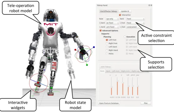
Teleoperation interface: One of the most frequently used feature panels is the teleop panel. Together with the visualization window, the teleoperation panel (shown in Figure 4) provides the operator with a rich set of controls to design whole-body manipulation poses and trajectories following from a set of geometric constraints. Through this interface, the operator can constrain the position and/or orientation of the robot’s hands, feet, and pelvis and the angles of individual joints. Our custom inverse kinematics solver also allowed the operator to express quasi-static stability constraints by requiring that the robot’s center of mass remain within the support polygon of one or more of the robot’s feet (Fallon et al., 2015a). Together, the kinematic and quasi-static constraints allowed the operator to describe complex whole-body motions with changing contact states through the teleoperation interface.
2.2 Task panel
The task panel window is shown in Figure 3. The task panel contains a tabbed widget, with each tab holding the task plan for one of the eight tasks in the competition. In the competition, the task panel occupied the full screen of one of the primary operator’s monitors and the main Director window occupied a second. As long as there are no failures in execution, the task panel occupied the complete attention of the primary operator. The task panel is a visual representation of the shared autonomy system: it steps through the hierarchy of tasks and asks for inputs from the operator as required to complete the tasks. If something fails, for example, the door fails to unlatch after turning the handle, the task sequence is paused (in some cases, through automatic failure detection, and in other cases by operator intervention) and the operator may switch focus to the main window to manually operate the robot back to a state where the autonomy system is capable of resuming control. The task panel interface was designed so that any individual on our team could be capable of operating the robot to complete tasks. When the system asks for an input from the operator the requested input is clearly stated and designed so that it is not sensitive to the variation in possible responses from the operator. For example, a skilled operator is not required to interact with
Ac#ve constraint selec#on
Supports selec#on
Interac#ve
widgets Robot state model Tele-‐opera#on
robot model
Figure 4: The teleoperation interface provides the user with a rich set of preset constraints that are adjusted with widgets in the visualization window. The robot’s current configuration is shown as a translucent model, and its desired configuration is shown as the full opaque model. In this example, the operator has indicated constraints on the position and orientation of the robot’s left hand and right foot. The operator has also indicated that the robot’s final posture should keep its center of mass near the center of the robot’s left foot, ensuring that the robot will be able to stably balance on just that foot.
the perception system. An operator need only click on a camera image anywhere on the door in order to convey the required information to a door fitting algorithm. However, if a task fails and manual intervention is required, we found that this operational mode required user training and knowledge of the specific task flows in order to manually operate the robot around the failure and to continue autonomous operation.
Layout: Tabs across the top of the panel in Figure 3 switch between competition tasks. The text area at the bottom of the window displays simple status messages when each task starts and completes. If a task fails for any reason, the failure is displayed in red text so that the operator may quickly locate a description of the detected failure. Above the text area, the task panel is divided into three columns. The central column is the main focus: it contains a tree list of the task hierarchy. In the figure, a user prompt task is active, so it displays the message Please approve the footstep plan and displays accept and reject buttons. The interface includes controls to pause, continue, or step through the task sequence. The user can either step through the task sequence conservatively or allow continuous task execution. Task parameters (in the left column) were used to alter task behaviors, for example, to switch hands used in manipulation, or to select a grasping strategy. The right column contains a list of button macros that can be used to execute some steps of the task manually. In normal operation the task parameters and button macros are not needed, but may be used by the operator during edge cases when the planned task sequence is not compatible with the current situation. Section 4.1 describes such a situation that arose during the Day 1 competition run where the manual controls were necessary to cope with the situation. Section 3.2 describes the programming model underlying the task panel user interface.
3
Programming Models
This section describes the programming models we used to implement our approach to task autonomy, combining a human operator and a user interface with a task planning system. In addition to user interfaces, well designed programmer interfaces are a key component to successful shared autonomy. These interfaces allowed for easy and rapid extension of the interface by many members of the team during the development and testing of the complete system.
3.1 Affordance model
When a physical object was to be interacted with, it was denoted to be an affordance, which combined a 3D model of the object with metadata describing the modes of interaction with it. One such set of metadata is a set of named reference frames relative to the body frame of the object. The combination of geometry and annotations of the form of reference frames are used as input to build constraints for motion planning queries called from the task execution system. This affordance model proved a natural way to structure our system’s interaction with objects in the world, although our library of affordances is limited to objects that are relevant specifically to the DRC competition (door handle, valve and drill for example), and a set of basic geometric shapes (box, cylinder, prism, and sphere for instance). Our approach to the generalization of affordances was to implement a segmentation routine that would cluster objects in the point cloud and return the convex hull for each one of them. Each convex hull is an instance of the affordance model and therefore treated as such for planning purposes.
The location of an affordance or one of its constituent frames may be updated by any process (a fitting algorithm or a user interface) and is synchronized between the user interfaces, i.e. if the position of an affordance is updated, the corresponding virtual object will be re-rendered in the new position in all instances of Director. Because the affordances were synchronized in this manner, it was straightforward to parallelize piloting tasks across multiple operators when the need arose: for example one operator could be dedicated to perception tasks, such as manually refining the positioning of a valve or drill using the latest perceived point cloud, while concurrently another operator could be dedicated to planning tasks, such as guiding the robot through a task queue for walking to approach the affordance.
Object model: The left dock of the main UI window contains the scene browser panel and properties panel. These are visual representations of the underlying object model within the application. The object model groups items in named collections using a tree hierarchy which takes inspiration from the concept of a scene graph which is common in 3D visual rendering applications. The object model stores a variety of object types, including robot models, affordances, coordinate frames, point clouds, terrain maps, motion plans, and footstep plans. Each object’s interface is presented in the form of modifiable properties. Properties can be edited by the user, or automatically by a task execution. Crucially, the object model was used as a data store for tasks to pass data through the execution pipeline, and to present data to the user for approval or adjustments.
3.2 Tasks
Subtasks required to execute a complete DRC task were implemented with callable Python objects and functions. Many subtasks were parameterized and reusable, while others were customized for purposes targeted toward specific tasks. As an example, the following is a typical sequence of task executions and the subtasks used: fit drill, approve drill, plan reach, approve manipulation plan, execute plan, wait for execution, close gripper. The name plan reach in this example refers to an affordance specific planning function—a function that plans a reaching motion to bring the end-effector to a grasping location around the drill affordance. A typical planning task was parametrized to include the reaching side (left, right), and the name of the target affordance i.e. the drill. The task calls subroutines that construct the required
constraints based on the coordinate frames of the drill affordance, and then query the manipulation planner. The task waits for a response from the manipulation planner or information about a failure (for example, if the required drill affordance cannot be found or if the planner failed to find a feasible solution).
The approve drill and approve manipulation plan tasks are examples of user prompt tasks. The user prompt task presents a message to the user along with options to accept or reject. The task waits for a decision from the user and either completes successfully or raises an exception to pause execution of the task queue. User prompts give the user the opportunity to adjust an input to the system without having to actively intervene to pause execution. During the approve drill user prompt, the user can adjust the drill affordance pose if required. The adjusted pose will then be used in the subsequent planning task. The execute plan task publishes the manipulation plan on the committed plan channel which will be transmitted to the robot. This task completes immediately. The next task, wait for execution monitors the execution of the task by the controller until execution is complete. The last task in this example, close gripper, sends a small message that is received by the gripper driver.
Asynchronous task queue Task execution is brokered by an asynchronous task queue (ATQ). Each item in the queue is a task. A task is a standalone unit capable of performing some action(s) and returning success or failure. At any point in time, only the top task in the queue is active, and it may complete at some point in the future. If a task raises an error then the execution of the task queue is paused, and the task panel user interface displays this state to the user. When the task queue resumes it will attempt to re-execute the failed task from the beginning, unless a different task has been selected in the user interface. A program may construct and begin execution of any number of asynchronous task queues. For example, as described in Section 2.2, each tab of the task panel maintains its own ATQ, but the task panel ensures only one queue is executed at a time. We found that it was useful to leverage the ATQ model in other locations of the user interface as well, to perform auxiliary operations. Rather than adopting a thread model, many actions in the user interface are dispatched (queued) for asynchronous execution. We implemented an asynchronous task queue ourselves in our application library so as to maximize simplicity and control over the design, however the concepts are borrowed from the field of asynchronous programming and are implemented in production systems such as Celery (an open-source Python implementation), and often found in job schedulers and web servers.
3.3 Guided perception
We adopted a guided perception approach to model fitting from point clouds and images. Fitting algorithms estimate the 3D pose of objects of interest in the environment which are represented using affordance models described in Section 3.1. Operators can provide guidance to the perception system by annotating search regions for the point cloud fitting algorithms. The operator can define annotations by clicking on displayed camera images, or by clicking on 3D positions in a point cloud. For the competition we preferred annotations on 2D camera images because it required less precision than point cloud annotations. For instance, during the valve task, we were required to fit a valve affordance to the valve in the point cloud. As shown in Figure 5, the operator reduces the search space by indicating the region where the valve is located by annotating two points that surround the valve, as visualized by two points connected by a green line in Figure 5 (left). Using only this two-click input over the 2D image, the algorithm proceeds to fit the valve in the 3D point cloud and creates the affordance as shown in the 2D view in Figure 5 (middle) and the 3D view in Figure 5 (right). Some fitting algorithms succeed with high probability without operator provided search regions, but operator input can still be useful to approve the estimate 3D pose prior to continuing with planning based on the affordance models. We can also provide guidance by designing task specific perception algorithms, where some intuition about the task is encoded into the algorithm.
As an illustrative example, we discuss the fitting of a running board platform attached to the Polaris vehicle during the egress task (Figure 6). During this task the robot steps off the platform 20 cm to the ground
Figure 5: Fitting the valve affordance. User provides simple annotation in the 2D camera image (left), the fitting algorithm fits a valve affordance, results shown in 2D (middle) and in the 3D view (right).
as shown in Figure 8. The foot swing trajectory must be precisely planned relative to this platform. We modeled the platform as a box-shaped affordance and fit it to the front edge of the platform that was detected in the LIDAR point cloud.
Figure 6: Fitting the running board platform used for vehicle egress. Left and Center show stages of the fitting algorithm. Red and blue points are candidate edge points with the red points being inliers. From the edge the pose of the platform affordance (in gray) is produced. Right shows the affordance being used to automatically place a precise overhanging footstep and a swing trajectory.
Algorithm 1 Platform fitting algorithm
1: function FitPlatform(q, p) 2: fs← stanceFrame(q) 3: x, y, z ← axes(f ) 4: p ← removeGround(p) 5: p ← cropToBox(p, fs, [1, 1, 0.1]) 6: pe← computeEdge(p, y, x) 7: l ← fitLineRansac(pe) 8: ls← projectToPlane(l, position(f ), z)
9: return frameFromPositionAndAxes(midpoint(ls), cross(ls, z), ls, z)
Algorithm 1 gives a sketch of the point cloud processing procedure to fit the pose of the platform affordance. We describe the steps of the algorithm in more detail to give the reader some idea of our approach to point cloud processing. Our processing algorithms combine task specific filtering with standard techniques such as RANSAC model fitting and normal estimation using the Point Cloud Library (Rusu and Cousins, 2011). The goal is to fit the edge of the running board with high accuracy, since the edge was to be used for footstep placement when stepping out of the vehicle. As seen in Figure 6 very few LIDAR point returns are collected from the platform due to occlusion by the robot body; only the front edge is visible. We describe each line of the fitting algorithm as follows:
2. stanceFrame() returns a homogeneous transform. The stance frame is defined with respect to the world coordinate system and located at the midpoint between the feet.
3. Extract the coordinate axes of the stance frame. Since the robot is standing on the platform, we can expect that the Z axis is perpendicular to the platform surface, and the X axis points toward the edge of the platform within ± 45 degrees.
4. Filter the point cloud to remove points on the ground, using a planar ground model.
5. Crop the input point cloud to a box of dimensions [1,1,0.1] meters, oriented and centered at the stance frame. Figure 6 displays these points in green, red, and blue.
6. Bin the points into bins perpendicular to the stance frame Y axis, and for each bin select the maximal point as projected onto the X axis. This yields a reduced set of candidate platform edge points, displayed in red and blue.
7. Fit a line model to the candidate edge points. Inliers are displayed in red, outliers are blue. 8. Project the line onto the platform surface which is defined by the XY axes of the stance frame.
9. Return a homogeneous transform that defines the pose of the platform affordance in the world coordinate system. The transform is constructed using the projected line and the Z axis of the stance frame.
This algorithm is in fitting with our shared autonomy model. It is written with some assumption of the initial pose, which is satisfied by the task sequence leading up to the invocation of the algorithm and the fit result is easily inspected by an operator. The fitting algorithms for other affordances are implemented with a similar approach.
4
Performance Evaluation at the DARPA Challenge Finals
This section describes the performance of the Team MIT Atlas robot in the DRC Finals with qualitative analysis of the usage pattern of the shared autonomy system on the user interface followed by quantative analysis in laboratory experiments.
We present a summary of each individual field task at the DRC Finals with an emphasis on the outcome of using the workflow implemented in Director. In particular, we describe the use of automation and teleoperation as it was required in the field, including a description and summary of the events that produced failures and therefore required more manual control using the workflow illustrated in Figure 1. We then illustrate the case for increased levels of autonomy by exploring the performance in the valve task during laboratory experiments when using different sets of features available to the operator in the user interface.
4.1 Summary of each task
Figure 7 presents a selection of task execution times collected during the two competition runs. On tasks where the shared autonomy system proceeded without interruption, execution times are consistent for each run. Tasks that required manual operator intervention were however slower: for example the door task on Day 1, and the terrain task on Day 2.
Driving and egress tasks: The first two tasks of the competition were driving and vehicle egress. To drive the vehicle the operator provided steering and throttle inputs based on video feedback (which had little delay) in teleoperation mode. The robot was sitting in the car in a way that the mapping for the teleoperation was straightforward: throttle inputs given by the operator using a physical slider mapped directly to the ankle joint angle, and steering inputs given by another operator using a steering wheel for
driving door
(opening) (walking through)door valve terrain stairs 0 50 100 150 200 250 300 350 400 Time (s) +35 s +228 s +1 s +7 s +66 s +13 s
Task Times on Day 1 and Day 2
Day 1
Day 2
Figure 7: Timing comparison between tasks executed on competition Day 1 and Day 2. Task completion success varied over the two days so we cannot directly compare all eight tasks; egress and drill are not shown due to lack of completion on at least one day. The door task required manual intervention of Day 1, and terrain required manual intervention on Day 2, and took longer as a result.
video games mapped to the wrist roll joint angle on the robot’s arm. Teleoperation was possible because the rules of the competition stipulated full bandwidth in the communication channel during this task. The stereo depth cameras were invaluable to inform the operator about vehicle speed and trajectory around obstacles. The system computed an estimated trajectory using the current turning radius of the vehicle and assisted the operator by rendering this estimated trajectory in 3D over the stereo depth colored point cloud. In addition, the drivers had access to 2D video from one of the cameras on the sensor head of the robot. Driving was 35 seconds faster on the second day run, which we attribute to improved operator performance. After completing the driving course the operator changed task panels to the egress task. The egress procedure was highly automated and the operator’s role was simply to approve automatically generated plans. These steps varied in complexity from opening the robot’s grippers, to changing the active contact points used by the controller to balance.
During preparation before the competition both tasks were successfully completed many times. Optimizing our semi-autonomous task sequence allowed us to halve the time for egress in the two weeks before the competition. However, a minor bug in our task sequency meant that on Day 1 an important step which was required between the driving and egress tasks was not completed: disabling the ankle throttle controller. This resulted in the ankle being incorrectly positioned when moved from the pedal onto the foot well. The operators realized the error and attempted to correct it manually, but ultimately it led to instability when the robot attempted to stand up, leading to a fall from the vehicle. This issue never occured in our laboratory testing because we were unable to consecutively test driving the car followed by then getting out of it due to space constraints.
Before Day 2, a task was added to the sequence to prevent the error from occurring again. With this simple fix the egress worked exactly as planned on our second run.
Door task: The door task involved opening and walking through an industrial doorway. The task interface encoded the sequence: walking to a carefully aligned location in front of the door; turning the handle; pushing the door open with a second hand; and finally walking through the door along a path carefully chosen to ensure clearance between the robot’s wide shoulders and the door frame.
Figure 8: Atlas robot performing the door task in our laboratory (left). Egressing from the vehicle, task 2, at the DRC Finals.
On Day 1, the fall from the car destroyed an actuator on our favored right arm. Thankfully, the flexible task execution system enabled by our mixed mode planning system and affordance models allowed us to switch the handedness of all single-handed plans with a single toggle switch. It also allowed us to skip over stages that would not work with the broken wrist joint, such as pushing the door open, while still automating the other aspects. Figure 7 demonstrates that a much greater amount of time was required on Day 1 during the manipulation stage of the door task due to operator teleoperation, which was required because of damaged sustained to precision encoder sensors in the arm during the fall. However, the timing of the non-manipulation aspect of the door task (walking through the door) was consistent due to a return to the automated task sequence. The right arm was repaired and on Day 2 the entire door task was executed quickly and without deviation from the autonomy script.
Valve task: The valve task was the first task after entering the building through the door. The network blackout rules begin immediately upon crossing the threshold of the door. Our recorded execution time for the valve includes the approach to the valve starting from just after the door. Due to the broken right wrist actuator, we turned the valve using the robot’s left end-effector on Day 1, but preferred the right end-effector on Day 2. Execution is similar, but the robot’s planned stance location in front of the valve depended on the handedness selected. The valve task sequence ran without operator intervention on both days, and execution time was consistent between the runs, with a small difference of only 7 seconds. This demonstrated the flexibility in our approach.
Drill task: The procedure to turn on the drill requires bi-handed manipulation and was the most complex task. The steps include: pick up the drill from a shelf with one hand, turn it on with the other, cut a circle, knock out the circle to create a hole, drop the drill. Each sequence requires several planned trajectories and updates to the affordance models using perception data.
The task was skipped during the Day 1 run because of the broken wrist actuator meant that we could not turn the tool on. On Day 2 our planned task sequence performed very successfully. We used stereo visual servoing to press the drill button by successively minimizing the distance between the drill button (held by the right hand) and the thumb on the left hand. The human provided the precise location of the button by clicking on a camera image.
We then walked to the wall and started cutting, however we failed to cut the wall deeply enough to cut out the required hole. After inserting the drill into the wall a temperature sensor indicated that the wrist actuator was overheating requiring the operator to halt operation to allow it to cool. While we believe that this was unrelated to the missed cut, it meant that we ran out of time to re-attempt the drill task (the drill had a safety shut off after 5 minutes).
The cutting trajectory included significant use of back motion as the shelf storing the drills was close to the cutting wall. We believe that this execution was imprecise as a result and that a more compliant control strategy, such as (Sentis et al., 2010), would have achieved a more robust cut. In retrospect, comparing to approaches taken by other teams our bi-handed approach was quite complicated and had a role to play in our failure to achieve this task each day.
Finally, when dropping the drill to move to the next task we uncovered a bug in our system that was unknown despite significant amounts of randomized testing. The motion plan during this sequence caused the robot to twist its pelvis around a yaw of 180 degrees. This exposed a simple wrap-around bug (where 180 degrees became -180) which caused a control instability and a fall.
Surprise, terrain and stairs tasks: The surprise task was completed using a teleoperation mode to press a lever on Day 1, while on Day 2 we were behind time and skipped the surprise task (a plug insertion). We moved on to the mobility tasks of crossing an uneven terrain course and ascending a staircase. Our research group is specifically focused on locomotion and on each day we successfully completed the tasks. From our analysis we were the quickest of the teams to complete these tasks.
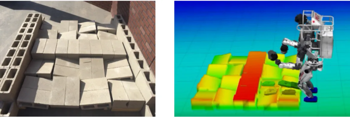
Unlike the manipulation tasks, where affordances are used as virtual representation of the physical objects to be manipulated, in the terrain and stairs tasks, affordances are used to represent the support surfaces for locomotion, such as the blocks in the terrain (shown in Figure 9) and the levels in the stairs. In this case, the guided perception module has a fundamental role in computing the segmentation of these objects from the point clouds and automatically fitting affordances to the relevant parts. The operator had the ability to perform modifications on the position and orientation of the affordances if needed. The task hierarchy consisted of fitting support surface affordances to the sensed data, loading pre-planned footsteps relative to those affordances, and then executing those footsteps. We had previously demonstrated the ability to autonomously plan footsteps over unmodeled terrain (Deits and Tedrake, 2014; Fallon et al., 2015b), but because the exact layout of the DRC terrain was known in advance, we chose to pre-plan footsteps for the given terrain.
Each subtask in the hierarchy also involved a check for operator approval, but during the competition almost no operator intervention was required. During the terrain task on Day 1 and the stairs task on both days, the operator interaction was limited to minor (roughly 1 cm) adjustments of the perceived positions of the locomotion affordances. During the terrain task on Day 2, our approach was more cautious and a little slower. Our operator observed a foot clipping a block while crossing the terrain and triggered the robot to take a recovery step (re-planning online) which stabilized the robot before we continued. The operator then planned two manually-chosen footsteps and resumed execution of the automatic task sequence.
4.2 Summary of autonomy interruptions
The nominal workflow for task execution is based on the task sequencing that the operator interacts with in the task panel, i.e. the outer loop shown in Figure 1. This task sequencing, shown in the task queue in Figure 3 includes steps of three main types: (1) requires operator’s input to an autonomous component, such as the valve fitting process explained before; (2) are fully autonomous, such as reaching to the valve; (3) are only manual by request of the automatic task sequencing, such as manually adjusting the fit of the valve when the task sequencing requires the operator to confirm or adjust the current fitting. A break on the nominal workflow is expected to happen only because of a system failure or unforeseen events that shall alter the task sequencing. These events require more manual intervention from the operator through
Figure 9: The terrain course at the DRC Finals (left). The terrain model as estimated by the perception system and represented to the planning system as a height map (right).
teleoperation. The teleoperation process is still assisted by the automatic motion planner, once the operator has manually indicated a goal pose and a set of constraints. The reason for each event has been explained in the summary of the tasks in Section 4.1.
Task failures can be detected automatically or detected by an operator. Although there is great benefit to detecting failures automatically, the detection creates cognitive burden for the operator because the operator has to read and understand the failure. For this reason, we preferred to anticipate most of the events that would potentially require the operator’s intervention, and include them in the task sequencing as a request to the operator, as opposed to leaving them only to reactive intervention. In the months leading up to the competition we refined our task sequences to replace tasks that had a low success rate with tasks that incorporate shared autonomy to increase success rate. The typical case is a task that uses a perception algorithm to localize an affordance. The task will prompt the user to verify the affordance pose before proceeding with autonomous manipulation.
For this reason, in the competition the only task failures that led to pausing the task sequence were operator detected failures of unforeseen events. These events are summarized in Table 1, and details of these events have been described in the preceding section.
Day 1 Day 2
Task Interrupts Auto Plans Teleop Plans Interrupts Auto Plans Teleop Plans
Driving 0 0 * 0 0 *
Egress 1 6 0 0 9 0
Door 1 4 6 0 9 0
Valve 0 9 0 0 9 0
Drill n/a n/a n/a 1 19 11
Surprise 0 4 12 n/a n/a n/a
Terrain 0 2 0 1 2 0
Stairs 0 3 0 0 3 0
Table 1: A summary of the number of task failures during the competition that led to interrupting the automatic task execution sequence, and the types of plans executed for each task. During the driving task joint commands were streamed directly instead of using motion plans. N/a indicates that we did not attempt this task.
4.3 Contribution of shared autonomy interface
Director is the central hub of interaction with many components of a larger and complex system that includes perception, planning, control and communications. While it is possible to evaluate the performance of these components in isolation, the resulting performance of such a complex system is a combination of success of individual components together with the results of the interactions between them. Director interacts directly with each component and uses this information to create an unified representation of the robot’s world and actions that enables the operator to remotely control the robot to execute a variety of locomotion and manipulation tasks using a shared autonomy framework. A fundamental contribution of the interface is to properly integrate the interaction with the overall system into a single usable interface that exploits the advantages of the other components while keeping a coherent high-level view of the system, and we use our field performance during the DRC Finals as a proxy to evaluate its efficacy.
Ideally, we would quantify the contribution of the shared autonomy interface to our overall performance at the DRC competition relative to all the other components of our robot system. It is difficult to make direct comparisons between Director and our previous user interface used at the DRC Trials in December 2013 because many components of our robot system have changed, and the competition tasks and rules changed. Additionally, the DRC Finals had too few experiments to draw any conclusions.
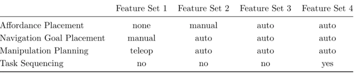
Instead, we have performed an evaluation of the time taken to complete a representative task while incremen-tally enabling the different levels of autonomy of our system for a series of repeated experiments performed in our laboratory. The representative task required the operator to command the robot to approach a valve, grasp and turn it while using one of the following sets of features, which are ordered in terms of increasing autonomy:
• Feature Set 1: Teleoperation. The operator manually placed a navigation goal near the valve to create the walking plan. To turn the valve, the operator used our teleoperation interface to raise the arm, grasp, and turn the valve.
• Feature Set 2: Affordance-based planning. The operator manually aligned a valve affordance, then invoked task specific planners to generate a navigation goal relative to the valve. After walking to the valve, the operator manually re-adjusted the valve affordance model to match the LIDAR point cloud. The operator used task specific planners to perform the manipulation task.
• Feature Set 3: Affordance-based planning and automatic fitting. The operator used a perception fitting algorithm to automatically align the valve affordance. Everything is the same as feature set 2, except automatic fitting was also used.
• Feature Set 4: Task sequencing. The task panel is used to automatically sequence the task. Automatic fitting and affordance-based planning are also used. In this mode, the operator does not have to click in the interface to invoke the task specific planners for navigation and manipulation. The task queue automatically steps through the task while the operator supervises the execution. This feature set was used at the DRC Finals.
Figure 10 shows the timing results of the task repeated for 10 trials with each feature set. The trials were performed by the same operator over three different sessions with the order of experiments randomized. Table 2 gives an overview of the level of autonomy used for each system component in each feature set. Even though this is a limited analysis, it demonstrates the case for increased levels of autonomy by measuring the performance benefit of adding assisted perception and planning. Note that the task time variance for teleoperation is higher due to the variability in the manner that the operator carries out manual control, whereas task time is more predictable when the task panel is used to sequence the task.
Feature Set 1 Feature Set 2 Feature Set 3 Feature Set 4 0 50 100 150 200 250 300 350 400 Time (s)
Time Trials of the Valve Task with Varying Feature Sets
Teleoperation
Affordance Based Planning
Affordance Based Planning
& Automated Perception
Affordance Based Planning
& Automated Perception
& Task Automation
Figure 10: Valve task trial data collected from laboratory experiments illustrates the performance benefit (measured in task completion time) of varying feature sets within the Director user interface. The order of each experimental run was randomly drawn. Broadly speaking, the level of autonomy increases from left to right.
Feature Set 1 Feature Set 2 Feature Set 3 Feature Set 4 Affordance Placement none manual auto auto Navigation Goal Placement manual auto auto auto Manipulation Planning teleop auto auto auto
Task Sequencing no no no yes
Table 2: Level of autonomy used for each system component in the 4 feature sets used in valve experiments.
5
Discussion
In this work we have described the general principles around which our system’s shared autonomy was based. The two main principles were 1) that all task planning was affordance centric and 2) that general purpose motion planning was used to accomplish each task. While the Challenge accelerated our progress on these fronts enabling the execution of entirely novel tasks, we have identified key limitations which demand the attention of the research community.
Our affordance representation was of central importance to our semi-autonomous system. Our original approach, was discussed in (Fallon et al., 2015a), focused on parameterizing object degrees of freedom only. For Director, we attached the motion planning and object fitting functions to the software representations of our objects of interest. We further extended the representation to encode properties relevant to task execution. As an example, we encoded the pose of where the robot should stand and the posture it should take before grasping an object, as well as any custom motion planning constraints.
We have, however, found it challenging to transfer this information from one task to another without explicit modification by our UI designer. While it is possible to reuse existing object fitting algorithms, modification of the motion planning problems are more difficult as in many cases specific cost functions or constraints are required to interact with new affordances. In practice the operator needed to resort to teleoperation to